EP1281239B1 - Signalüberwachung auf sliding-window-basis - Google Patents
Signalüberwachung auf sliding-window-basis Download PDFInfo
- Publication number
- EP1281239B1 EP1281239B1 EP01918132A EP01918132A EP1281239B1 EP 1281239 B1 EP1281239 B1 EP 1281239B1 EP 01918132 A EP01918132 A EP 01918132A EP 01918132 A EP01918132 A EP 01918132A EP 1281239 B1 EP1281239 B1 EP 1281239B1
- Authority
- EP
- European Patent Office
- Prior art keywords
- signal
- window
- samples
- transition
- sample
- Prior art date
- Legal status (The legal status is an assumption and is not a legal conclusion. Google has not performed a legal analysis and makes no representation as to the accuracy of the status listed.)
- Expired - Lifetime
Links
Images






Classifications
-
- H—ELECTRICITY
- H03—ELECTRONIC CIRCUITRY
- H03K—PULSE TECHNIQUE
- H03K5/00—Manipulating of pulses not covered by one of the other main groups of this subclass
- H03K5/19—Monitoring patterns of pulse trains
Definitions
- the present invention generally relates to signal supervision, and more particularly to a method and device for signal monitoring.
- a signal monitor is an arrangement for monitoring the behavior and/or status of a signal. As long as the signal behaves as normal, the signal monitor confirms the existence of a valid signal. On the other hand, if the signal behavior deviates from normal, an alarm is normally raised so that appropriate actions can be taken.
- the performance evaluation of a signal monitor is normally based on detection time and reliability. In high-performance applications, it is extremely important that the monitor has a fast detection speed so that a signal failure can be detected as soon as possible. High reliability is also essential and it is normally required that the monitor can handle different metastability situations.
- the monitored signal In high-frequency applications, the monitored signal generally has to be sampled by a sample clock of much higher frequency, so-called oversampling. However, when the frequency of the monitored signal reaches higher and higher levels, it may not be possible to generate a high-frequency sample clock for oversampling purposes, at least not to a reasonable cost.
- U.S. Patent 5,719,508 relates to a digital loss of lock detector specially designed for a phase-locked loop where the mandatory phase relation between the locked signal and the reference signal at phase lock is 90°.
- the loss detector includes a number of latches, which are utilized to provide error signals for a number of possible erroneous relations between the locked signal and the reference signal.
- U.S. Patent 4,852,124 relates to a clock signal extractor which is based on a shift register, a transition detector and a frequency divider for deriving the extracted clock signal.
- a bipolar input signal is sampled into the shift register by a sampling signal having a frequency which is a multiple of the frequency of the input signal.
- the first outputs of the shift register are combined in the transition detector, which detects the presence or absence of a single transition from 0 to 1 and generates a corresponding transition detection signal.
- a correction logic circuit in the frequency divider compares the logic state of the frequency divider with the transition detection signal, and commands, based on the phase error thus detected, a phase correction of the extracted clock signal.
- U.S. Patent 5,926,047 relates to a loss-of-signal detector specially designed for a delay-locked loop (DLL) of the type which produces a plurality of output signals in response to a clock signal.
- the loss detector comprises a first monitor and a second monitor.
- the first monitor receives a first output signal from the DLL
- the second monitor receives a second output signal from the DLL, each monitor being clocked by the clock signal and the inverse of the clock signal.
- the first output signal and the second output signal has a predetermined phase relation which prevents a racing condition from developing at the monitors.
- the output signals of the monitors are processed by a number of logic gates in order to generate an alarm when the first output signal of the DLL ceases to transition at the frequency of the clock signal.
- U.S. Patent 5,138,636 discloses a signal loss detection circuit for a digital signal receiver of the type that includes a clock recovery circuit, which reconstitutes the received clock. A loss of signal is manifested by an absence of pulses in the reconstituted clock.
- the circuit for detecting loss or recovery of the received signal comprises a counter for counting pulses of the reconstituted clock lying within a count window. If the counter reaches a predetermined count state during a count window, signal recovery is indicated. Otherwise, signal loss is indicated.
- GB-A-2 304 477 discloses signal processing methods for determining the moisture content of a mix in a concrete mixing system. Noise spikes caused by voids in the mix and the passage of mixing blades past the sensor are avoided by determining when moisture signal values are stable on the basis of a statistical measure of dispersion, e.g. the variance or standard deviation, of signal samples in moving windows. If it is detected that the signal values are not stable, the most recent stable value is output.
- a statistical measure of dispersion e.g. the variance or standard deviation
- the present invention overcomes these and other drawbacks of the prior art arrangements.
- Yet another object of the invention is to devise a monitoring mechanism that can be formed as distributed detection algorithm and parallelized so as to reduce overall complexity and detection time latency.
- the invention is generally directed towards sample-based signal monitoring, where a signal is sampled to obtain a discrete sample representation that is analyzed for monitoring the status and behavior of the sampled signal.
- the general idea according to the invention is to slide a sample window over the sampled signal and determine whether the samples currently within the window are representative of a valid transition sequence.
- the valid transition sequence includes at least two transitions, each transition being a change of logical levels between samples of the window.
- the existence of a valid signal is confirmed as long as a valid transition sequence is present in at least one of a predetermined number of consecutive windows. Signal failure is indicated if no valid transition sequence is present during the predetermined number of consecutive windows.
- the sample window is formed of M samples, where M is an integer equal to or greater than 3.
- M is an integer equal to or greater than 3.
- the actual length of the sample window is dependent on the number M of samples forming the window as well as the distance between the samples.
- the length of the window must be longer than the valid transition sequence in order to allow detection of the sequence within the window.
- the window is adapted to the length of the pulse width or pause width of the signal, and for period time detection, the window is adapted to the period time of the signal.
- the distance between consecutive samples in the window is smaller than the shortest of the pulse width and the pause width of the signal to ensure sufficient detector resolution for general applications.
- the sliding-window technique according to the invention allows for pulse width detection down to duty cycle variations without the use of an explicit control algorithm for aligning the detection window and the reference sample clock edges to the monitored signal transitions.
- each window among said predetermined number of consecutive windows is associated with an individual sub monitoring mechanism for determining whether the samples within the current window are representative of a valid transition sequence.
- each window among said predetermined number of consecutive windows is associated with an individual sub monitoring mechanism for determining whether the samples within the current window are representative of a valid transition sequence.
- the validity of the signal is confirmed only as long as a valid transition sequence is present in each consecutive window.
- the condition for confirming validity is fulfilled as long as a valid transition sequence is detected in at least one window of a whole ensemble of consecutive windows.
- the number of consecutive windows in the ensemble of windows generally corresponds to the number M of samples that form the sliding window.
- M of samples in the window is highly dependent on the particular application and may range from M being equal to 3 in cases where the monitored signal and the sample clock signal are synchronous and there is a well-defined phase relation between the two signals, to M being equal to or greater than 6 for asynchronous signals with large frequency and duty cycle deviations and poor jitter characteristics.
- the invention thus offers a flexibly adaptable monitoring mechanism, which by simply adjusting the number M of samples in the sliding window and the distance between consecutive samples, can be adapted to handle various applications as well as possible metastability situations occurring for asynchronous signals.
- the invention furthermore proposes a multi-phase sampling technique according to which a number of phase-shifted sample clocks of the same frequency are generated for the purpose of sampling the signal to be monitored.
- Various delay elements may be used to create the phase-shifted sample clocks without using a high frequency clock that otherwise would be introduced with oversampling. Higher-frequency oversampling is thus replaced by a higher resolution in the time domain.
- phase-shifted sample clocks are synthesized directly from the monitored clock by delay elements.
- the general idea according to the invention is to monitor a sampled signal by step-wise sliding a window of a predetermined number M of samples over the sampled signal, and determining whether the samples currently in the window include a valid transition sequence.
- the existence of a valid signal is confirmed as long as a valid transition sequence is present in at least one of a predetermined number of consecutive windows. If the validity can not be confirmed, there is generally a signal failure, for example in the form of a stuck low or stuck high fault.
- a transition sequence is a sequence of at least two transitions. Accordingly, a valid transition sequence may for example be a low-to-high "up” transition followed by a high-to-low “down” transition, or any other predefined sequence of transitions.
- a valid transition sequence includes a first transition, and a later reverse transition in a position consistent with the expected pulse/pause width of the signal (taking into account possible variations in the monitored signal).
- the valid transition sequence may thus alternate between a first sequence defined by an up transition followed by a down transition, and a second sequence defined by a down transition followed by an up transition, where the two transition sequences are connected seamlessly to each other.
- the minimum number M of samples in the sliding sample window is normally equal to 3, and such a minimum window is applicable for example in situations where the monitored signal and the sample clock are synchronous and the phase relation between the two signals is well-defined.
- the number M of samples in the sliding window must be higher in order to ensure reliable monitoring of the signal.
- M is selected to be equal to or greater than 6, although a smaller number is possible also for the asynchronous case under certain circumstances.
- Fig. 1 is schematic block diagram of a signal monitor/loss detector according to a basic embodiment of the invention.
- the signal monitor 10 basically comprises a sampler 20 and an analysis unit 30.
- the sampler 20 is a general circuit for sampling a signal M to be monitored into a memory buffer 21.
- the sampler 20 may be a shift-register based circuit using a higher-frequency sample clock S for oversampling the monitored signal.
- the monitored signal M is sampled into an array of edge-triggered memory elements by means of a number of phase-shifted sample clocks S I to S N .
- the analysis unit 30 may be implemented in hardware logic, or as software in a computer system based on for example a digital signal processor (DSP) or equivalent.
- the analysis unit 30 basically includes a sliding window unit 31, a transition sequence search unit 32 and a unit 33 for validity check.
- the units 31 to 33 are preferably realized as software functions, procedure or modules.
- the sliding window unit 31 and the search unit 32 are preferably integrated in the same hardware logic, as will be explained later on with reference to Fig. 4 .
- Figs. 2A-B are schematic timing diagrams illustrating the basic principles of the sliding-window technique according to the invention.
- Fig. 2A illustrates a signal M to be monitored, a sample clock signal S for sampling the signal M, and a resulting discrete sample representation U of the monitored signal.
- the monitored signal and the sample clock signal are illustrated as synchronous, the phase relation between the two signals being optimal for sampling purposes.
- the monitored signal M has a duty cycle of 50%, with a pulse width equal to the pause width.
- a valid transition sequence is defined as a first transition followed by a reverse transition in a position consistent with the expected pulse or pause width.
- the sliding window has to be large enough to catch a pulse or pause.
- the minimum requirement on the window length in this case is three samples, and the distance between consecutive samples of the window generally has to be equal to or smaller than the pulse width in order to ensure sufficient resolution.
- the distance between consecutive samples is set to be equal to the pause width. This works well for the optimal phase relation between the monitored signal and the sample clock illustrated in Fig. 2A . In general, however, a distance between consecutive samples that is much smaller than the shortest of the pulse and pause width is recommended.
- Fig. 2A illustrates a number of consecutive and overlapping windows W 1 to W4 formed by sliding a window of the minimum of 3 samples over the sampled signal. For each consecutive window, it is determined whether the window includes a valid transition sequence.
- window W1 it can be seen that the signal M includes a first transition as well as a second reverse transition within the window.
- This so-called valid transition sequence is detected in the sample representation U of the signal by comparing the logical levels of adjacent samples within the current window. A transition is normally detected as change of logical levels between adjacent samples.
- a first transition is detected as a change from 0 to 1 between the first and second sample, and a second reverse transition is detected as a change from 1 to 0 between the second sample and the third sample of the sample representation U.
- window W2 a first transition is detected as a change from 1 to 0, and a second reverse transition is detected as a change from 0 to 1.
- a valid transition sequence is also found in window W3.
- window W4 only a single transition from 1 to 0 is detected, and this transition can not be matched with an expected reverse transition (the actual signal is indicated by a solid line, whereas the expected normal signal is indicated by dotted lines).
- the sliding-window technique according to the invention is capable of providing fast loss detection.
- Fig. 2B is similar to Fig. 2A , but now the monitored signal M is illustrated as having a different duty cycle so that the pulse width is twice the length of the pause width.
- the resolution is normally adapted to the shortest of the pulse width and the pause width.
- the distance between consecutive samples is selected to be equal to the pause width.
- the sliding window is naturally adapted to the longer pulse width, although it is possible to adapt the window to the shorter pause width.
- the number M of samples of the sliding window is selected to be equal 4. This in fact allows detection of individual pulses as well as individual pauses in the signal.
- any valid transition sequence in the monitored signal can be securely detected.
- a valid transition sequence is detected as a positive pulse with a transition from 0 to 1 and a subsequent transition from 1 to 0.
- a valid transition sequence is detected as a pause, or a negative pulse with a transition from 1 to 0 and a subsequent transition from 0 to 1.
- Valid transition sequences are also found in windows W3 and W4. In window W5, however, only a single transition is detected. Since the setting of Fig. 1B requires that a valid transition sequence is present in each consecutive window for confirming the validity of the signal, it can be concluded at the end of window W5 that the monitored signal M is no longer valid.
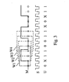
- Fig. 3 is a schematic timing diagram illustrating the monitoring of an asynchronous signal by means of a detection mechanism that incorporates first order metastability correction.
- a signal M that is asynchronous to the sample clock signal S
- metastability situations may arise when sample clock transitions occur in the vicinity of transitions of the monitored signal, a fact well-known in the art.
- the monitored signal is sampled by the sampling edge of the sample clock close to a transition in the monitored signal, it may not be possible to obtain a well-defined sample value. In such a situation, it is not clear whether the monitored signal really has transitioned or not and hence the sample value may be indefinite.
- indefinite sample values are indicated by X in the sample representation U. The minimum distance between sample clock transitions and monitored transitions required for secure sampling may vary, depending on the particular implementation of the monitor.
- the sliding window hence includes a total of 5 samples, two more samples than required for a synchronous signal. Sliding the window over the sample representation results in the formation of a series of consecutive windows, of which only windows W1 to W4 are explicitly shown.
- the first window W1 it is apparent that the monitored signal M includes a pulse, but in the sample representation "0 X 1 1 0" of window W1, one of the samples has been trashed (X) due to metastability.
- X X 1 1 1 0
- the positive pulse is detected as a first transition from 0 to 1 determined from the first and third samples of the window, and the second transition from 1 to 0 is determined from the third and fifth samples as well as the fourth and fifth samples of the window.
- the positive pulse can not be detected, but since the pulse already has been detected by the first window W1 this is of no importance.
- the general condition for confirming validity is based on an ensemble of consecutive windows. Validity is generally confirmed as long as at least one window of the ensemble of consecutive windows includes a valid transition sequence. The number of windows in the considered ensemble of windows is at least partly dependent on the level of sample redundancy.
- the next valid transition sequence is the connected negative pulse, and this transition sequence is captured by the third consecutive window W3 as well as the fourth window W4.
- metastability correction requires a greater number M of samples within the sliding window compared to a monitoring mechanism without any correction capabilities. It may thus seem necessary to increase the frequency of the sample clock in order to squeeze a further number of samples into a sliding window that is adapted for a given pulse width. For high-frequency applications this would be a severe limitation.
- the invention substantially reduces this problem by a multi-phase sampling technique, which will be described in detail below with reference to a preferred embodiment of the invention.
- the invention proposes a multi-phase sampling technique according to which a set of N phase-shifted sample clocks S 1 to S N of the same frequency are generated for the purpose of sampling the signal to be monitored.
- phase-shifted clock signals for example by delaying a master clock using a number of delay elements in a conventional manner, or from division and decoding of a higher clock rate if such is available.
- oversampling with a much higher sample clock frequency compared to the supervised signal is replaced by resolution in the time domain, imposing harsh requirements on phase accuracy.
- the problems of oversampling still remain.
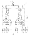
- Fig. 4 is a circuit diagram of a signal monitor/loss detector according to a preferred embodiment of the invention.
- the signal monitor 40 is implemented as a parallelized hardware structure, which comprises a number of edge-triggered memory elements such as digital flip-flop registers 41-1 to 41-N, one for each individual sample clock, a corresponding number of sub monitors 42-1 to 42-N (out of which only two are illustrated) for generating individual validity indications LOS(1) to LOS(N), and a logic element 43 for forming a compound alarm signal (LOS) from all the individual validity indications.
- edge-triggered memory elements such as digital flip-flop registers 41-1 to 41-N, one for each individual sample clock, a corresponding number of sub monitors 42-1 to 42-N (out of which only two are illustrated) for generating individual validity indications LOS(1) to LOS(N), and a logic element 43 for forming a compound alarm signal (LOS) from all the individual validity indications.
- LOS compound alarm signal
- each phase-shifted sample clock S i samples the monitored signal M as a data signal into a respective digital flip-flop register 41 to generate a corresponding sample value u i .
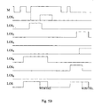
- the example of Fig. 5A illustrates an initialization period, a stuck high fault and a subsequent stuck low fault.
- the sample values u 1 to u N of the registers 41-1 to 41-N are fed to the sub monitors 42-1 to 42-N in the manner illustrated in Fig. 4 , and processed therein.
- the logic circuitry in each sub monitor implements a search procedure to determine whether a sample window associated with the corresponding sample phase includes a valid transition sequence or not. In this case, a valid transition sequence is found if a primary transition and an expected secondary reverse transition in a position consistent with the expected pulse/pause width of the monitored clock signal are found. If such a valid sequence is found, a corresponding individual validity indication LOS(i) is set high.
- the main LOS alarm is a compound alarm formed of all the individual indications. See also the timing diagram of Fig.
- the compound LOS signal is active low.
- the LOS signal is high and inactive as long as at least one individual LOS(i) signal is high. Normally the LOS signal goes low only when all individual LOS(i) signals are low, due to an abnormal behavior of the monitored signal.
- the phase-shifted sample clocks form a complete base vector system to describe the monitored signal M in the discrete sample clock time domain, as illustrated in the timing diagram of Fig. 5A .
- phase resolution or spacing ⁇ (or ⁇ T S in the time domain) with associated tolerances will ultimately determine how narrow clock pulses ⁇ T M (or pauses [1- ⁇ ]T M ) that may be detected depending on the set-up (t SU ) and hold (t H ) requirements on the registers used to sample the monitored signal.
- the duty cycle of the monitored clock signal is assumed to vary in the span ⁇ M ⁇ 1- ⁇ M .
- T S > 1 - ⁇ M ⁇ T M + 2 ⁇ t S
- Identification of a transition in the monitored clock state is basically accomplished by observation of a corresponding logic level shift in the sample representation u 1 ... u N between registers 41 with adjacent sample clock phases using a simple XOR gate which has a non-zero output only if the inputs are not equal.
- the primary transition search defined above is realized by three XOR gates followed by an OR gate.
- the secondary transition window [wl, wu] is wide enough to accommodate clock frequency and duty cycle deviations. Only valid transitions are of interest and since the detection window is wide enough to cope with all variations there is generally no need for any additional error correction efforts.
- the level r of redundant sample information from previous sample points (i-1,i-2,...,i-r) that is required the following holds true: wu + r + 1 ⁇ N 1 ⁇ wl ⁇ wu - 1
- the LOS signal is an alarm that is active low.
- Fig. 6 is a schematic timing and sample point diagram illustrating the sample window formed for a given sample phase ⁇ i , including a subwindow for an expected secondary transition.
- a sample window SW i is spanned up starting from the corresponding sample point i or the preceding sample point i-1, depending on the particular realization of the primary transition expression TR1(i), and extending substantially a whole sample period T S .
- a possible primary transition is monitored at the beginning of the sample window, and if found, a subsequent subwindow STW [i+wl, i+wu] is formed for the expected secondary transition.
- the sample information (associated registers) for a given sample window SW i is updated only once during a sample cycle triggered by positive (or negative) transitions in the sample clocks that form part of the particular sample window.
- Causality is preserved if the result of both edge detection and time out check for the secondary transition is processed and stored in a register only once in a sample cycle, at the first consecutive clock phase (sto) outside each respective secondary expected transition window (STW).
- each sub monitor 42 (see Fig. 4 ) has a register (DFF) for regularly storing/updating the individual validity indication LOS(i). No registers must be reloaded with new information before the store cycle is finished, requiring that the whole search process must fit into a single sample period. Please note the wrap around behavior from phase ⁇ N associated with sample clock S N to phase ⁇ 1 associated with sample clock S 1 .
- the clock supervision is managed by a divide and conquer technique that allows the problem to be discretisized in the time domain using a number of phase-shifted sample clocks to form overlapping subintervals, here referred to as sample windows (SW), one sample window around each sample point (see Fig. 6 ).
- SW phase-shifted sample clocks to form overlapping subintervals
- Each sample phase together with the necessary phases in the associated sample detection window are scanned with a distributed algorithm which is replicated for all other sample phases, forming a set of N overlapping sample windows (SW).
- at least one of the sample windows must include a valid transition sequence during a sample clock cycle (T S ) or else the monitored clock is disqualified.
- each individual sample window (SW i ) within a sample cycle (T S ) is associated with an individual sub monitoring mechanism, which determines whether the samples within the sample window (SW i ) include a valid transition sequence.
- these sub monitoring mechanisms are arranged for parallel as well pipelined operation.
- the parallelism originates from the hardware structure of the overall monitor 40, and the pipelined operation, which is an inherent feature of the sliding-window based search procedure, is manifested by the phase-shifted sample clocks.
- Fig. 7 is a schematic timing and sample point diagram illustrating a continuous stream of primary and secondary transitions triggering a chain of overlapping so-called adaptive sample windows. If a primary transition (P k ) is actually detected in a sample window and an opposite transition (S k ) occurs in the associated secondary transition window the alarm indication LOS(k) is valid for one sample clock period (until rel) and an adaptive sample window (ASW k ) is formed spanning from the primary transition to the store pulse (sto).
- P k primary transition
- S k opposite transition
- ASW k adaptive sample window
- the secondary transition (S k ) in this window becomes a primary transition (P k+1 ) in the next connected and overlapping adaptive sample window (ASW k+1 ) originating from the same (synchronous sample and monitored clocks) or another (asynchronous) individual sample window in the next sample cycle.
- the alarm management according to the invention is reversed so that the monitored clock must prove its existence (in some subinterval within a sample cycle) to avoid a clock loss indication.
- a fail state is introduced in relation to each individual sample window indicating FAIL when a primary transition is not followed by a secondary transition within the stipulated secondary transition window.
- a valid transition sequence in a sample window clears the alarm for substantially one sample clock period (T S ). Since the adaptive sample windows overlap, a high loss indication signal (no alarm) generated by the last valid secondary transition is released (rel) some time after a failed transition sequence is detected. Thus the alarm is delayed unnecessarily long.
- True pulse width detection within the current adaptive window is realized if the loss detection signal also takes into account that no fail states are allowed at any window edge in a manner similar to the loss generation described earlier.
- Fig. 8 is a schematic circuit diagram of a signal monitor/loss detector similar to that of Fig. 4 , except for a time-out mechanism when a primary transition is detected but no secondary transition occur.
- the monitor 50 of Fig. 8 comprises a number of edge-triggered memory elements 51-1 to 51-N and a number of sub monitors 52-1 to 52-N (out of which only two are illustrated). In this realization, however, at least one valid and no failed transition sequences are required at each instant to give an alarm free output (logic high). For this reason, each sub monitor 52 is adapted to generate an individual LOS(i) signal as well as an individual fail signal FAIL(i).
- Each individual fail signal FAIL(i) is formed in a similar manner as the individual LOS(i) signal, with the exception of an inverter arranged in the path from the secondary transition checking XOR gate to a further AND gate, which generates the individual fail signal.
- the main alarm signal ALARM is obtained from an AND gate 55 summing the compound LOS signal from the OR gate 54 and the compound FAIL signal from the inverter 57 following the OR gate 56.
- the compound FAIL signal is formed from all individual fail indications FAIL(i). Reference is also made to Fig. 5A-B again, where the improvement in detection time for the resulting alarm signal ALARM (LOS in Fig. 5B ) for a fail state loss detector is indicated by dotted lines.
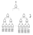
- Fig. 9 is a schematic diagram of a glitch detection mechanism that can be incorporated into the loss detectors of the invention. Glitch detection covering anomalous clock behavior other than pure clock loss requires a more sophisticated decision algorithm.
- T S Exactly one valid transition sequence is allowed in a complete sample cycle (T S ) including the contribution from all individual sample windows.
- glitch detection is accomplished by means of a branched off tree topology made up by successive XOR comparison of two values at each level. Such a topology will ensure that only one individual LOS signal at a time can inhibit the overall loss alarm.
- the sample and monitored clock periods must be roughly of the same order of magnitude (but still coping with the pulse width variations), thus involving two sets of transition sequences in each sample cycle.
- the pass condition is now exactly two transition sequences in each sample period still maintaining an adaptive detection window with bit-width reaction time.
- phase-shifted sample clocks are created or synthesized directly from the monitored clock.
- edge-triggered memory elements such as DFFs it seems impossible to supervise a clock signal and form an infinite hold alarm signal using no other means than the clock it self which by the very nature of the supervision problem disappears unexpectedly (high or low, etc.).
- Cascaded explicit or in logic networks implicitly formed delay units ( ⁇ T 1 ,..., ⁇ T n ) provide a means to create a set of n phase-shifted or delayed clocks, further on denoted M 1 , M 2 ,..., M n , more or less directly from the monitored clock signal M itself.
- the basic self-monitoring detector topology is adapted to reduce the complexity and thus fully benefit of all the additional information gained from the specific synchronous sample clock generation algorithm that will be explained below.
- the self monitoring loss detector 60 basically includes a number cascaded delay elements 61-1 to 61-3 for forming a corresponding number of delayed clocks M 1 to M 3 , two registers 62-1 and 62-2, two XOR gates 63-1 and 63-2 and two additional registers 64-1 and 64-2 for storing/updating individual LOS_H and LOS_L signals as well as a logic element 65 for forming a compound LOS signal.
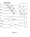
- Fig. 11 is a timing diagram for a loss detector using sample phases extracted from the monitored clock with two connected, possibly slightly overlapping, pulse width subwindows. At first the monitored clock M appears and the loss detector requires roughly one additional sample period to release the alarm signal so as to initiate the self-monitoring. Two error situations are depicted, namely when the monitored clock is shick low and high.
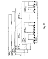
- Fig. 12 is a schematic diagram illustrating the basic partitioned sample window hierarchy together with the underlying time discrete sample point basis.
- a specific transition or alternatively a valid transition sequence, is defined and compared to observed transitions.
- a valid transition or transition sequence must occur in each subwindow related to a particular sample window to grant a positive individual LOS(i) signal:
- LOS i LOS PSW i ⁇ 1 • LOS PSW i ⁇ 2 • ... • LOS PSW in
- the compound LOS signal is normally formed as a superposition of all individual LOS(i) signals.
Landscapes
- Physics & Mathematics (AREA)
- Nonlinear Science (AREA)
- Synchronisation In Digital Transmission Systems (AREA)
- Manipulation Of Pulses (AREA)
- Analogue/Digital Conversion (AREA)
- Burglar Alarm Systems (AREA)
Claims (27)
- Verfahren zum Überwachen eines abgetasteten Signals,
dadurch gekennzeichnet, dass das Verfahren die folgenden Schritte umfasst:Schieben eines Fensters (SW) von M Abtastungen (ui), wobei M eine ganze Zahl gleich oder größer als 3 ist, über das abgetastete Signal;Bestimmen, ob die Abtastungen (ui), die sich gegenwärtig in dem Fenster (SW) befinden, eine gültige Übergangssequenz enthalten, wobei die gültige Übergangssequenz mindestens zwei Übergänge enthält, wobei jeder Übergang ein Wechsel von logischen Pegeln zwischen Abtastungen des Fensters ist;Bestätigen der Gültigkeit des Signals so lange, wie die gültige Übergangssequenz in mindestens einem einer im Voraus bestimmten Zahl von aufeinanderfolgenden Fenstern vorhanden ist; undAnzeigen von Signalausfall, wenn keine gültige Übergangssequenz während der im Voraus bestimmten Zahl von aufeinanderfolgenden Fenstern vorhanden ist. - Überwachungsverfahren nach Anspruch 1,
dadurch gekennzeichnet, dass jedes eine der im Voraus bestimmten Zahl von aufeinanderfolgenden Fenstern mit einem individuellen Unter-Überwachungsmechanismus (42, 52) zum Bestimmen, ob die Abtastungen in dem gegenwärtigen Fenster eine gültige Übergangssequenz enthalten, assoziiert ist, wobei die Unter-Überwachungsmechanismen (42, 52) für parallele als auch Pipeline-Operation angeordnet sind. - Überwachungsverfahren nach Anspruch 1,
dadurch gekennzeichnet, dass die gültige Übergangssequenz einen ersten Übergang und einen späteren umgekehrten Übergang in einer Position, die mit der erwarteten Impuls-/Pausenbreiten des Signals konsistent ist, enthält. - Überwachungsverfahren nach Anspruch 1,
dadurch gekennzeichnet, dass die im Voraus bestimmte Zahl von aufeinanderfolgenden Fenstern im Allgemeinen mit der Zahl M von Abtastungen, die das Fenster bilden, korrespondiert. - Überwachungsverfahren nach Anspruch 3,
dadurch gekennzeichnet, dass der Bestimmungsschritt die folgenden Schritte enthält:Suchen nach dem ersten Übergang als einen ersten Wechsel von logischen Pegeln zwischen Abtastungen des Fensters; undSuchen nach dem komplementären umgekehrten Übergang als einen umgekehrten Wechsel von logischen Pegeln zwischen späteren Abtastungen des Fensters, die in einem Unterfenster von Abtastungen, das mit der erwarteten Impuls-/Pausenbreite des Signals konsistent ist, resident sind. - Überwachungsverfahren nach Anspruch 5,
dadurch gekennzeichnet, dass das Unterfenster von Abtastungen breit genug ist, um Frequenz- und Leistungszyklus-Abweichungen bis zu einem im Voraus bestimmten Ausmaß aufzunehmen. - Überwachungsverfahren nach Anspruch 3,
dadurch gekennzeichnet, dass die Distanz zwischen aufeinanderfolgenden Abtastungen in dem Fenster kleiner als das kürzeste der Impulsbreite und der Pausenbreite des Signals ist und das Fenster von M Abtastungen länger als die Impulsbreite oder Pausenbreite des Signals ist. - Überwachungsverfahren nach Anspruch 1,
dadurch gekennzeichnet, dass der Bestimmungsschritt Vergleiche von aneinander angrenzenden Abtastungen als auch Vergleiche von Abtastungen, die durch eine oder mehr andere Abtastungen getrennt sind, enthält, wodurch verbesserte Fehlerkorrekturfähigkeit erhalten wird. - Überwachungsverfahren nach Anspruch 1,
dadurch gekennzeichnet, dass das abgetastete Signal durch Abtasten eines Signals mittels N phasenverschobenen Abtasttakten derselben Frequenz erhalten wird, wobei N eine ganze Zahl gleich oder größer als M ist, so dass das Fenster in einen einzelnen Abtasttaktzyklus passt. - Überwachungsverfahren nach Anspruch 1,
dadurch gekennzeichnet, dass das Verfahren weiterhin die folgenden Schritte umfasst:Anzeigen einer gültigen Übergangssequenz, wenn eine derartige Sequenz in dem gegenwärtigen Fenster gefunden wird. - Überwachungsverfahren nach Anspruch 1,
dadurch gekennzeichnet, dass das gleitende Fenster in eine Reihe von Unterfenstern unterteilt ist und der Schritt zum Bestimmen, ob die Abtastungen, die gegenwärtig in dem Fenster sind, eine gültige Übergangssequenz enthalten, die folgenden Schritte enthält:Bestimmen, für jedes der unterteilten Unterfenster, ob das Unterfenster eine gültige Übergangs- oder Unter-Übergangssequenz enthält, undFolgern, dass die Abtastungen, die gegenwärtig in dem Fenster sind, eine gültige Übergangsequenz enthalten, sofern mindestens ein Unterfenster seine korrespondierende gültige Übergangs- oder Unter-Übergangssequenz enthält. - Überwachungsverfahren nach Anspruch 1,
dadurch gekennzeichnet, dass das überwachte Signal ein Taktsignal oder ein Datensignal ist, wobei das Datensignal eine gegebene Bitbreite und eine im Voraus bestimmte Grenze für die längste Sequenz von Datenbits der gleichen Polarität hat. - Überwachungsverfahren nach Anspruch 1,
dadurch gekennzeichnet, dass die Gültigkeit des Signals so lange bestätigt wird, wie die gültige Übergangssequenz in jedem aufeinanderfolgenden Fenster vorhanden ist. - Überwachungsverfahren nach Anspruch 1,
dadurch gekennzeichnet, dass eine der M Abtastungen in dem Fenster eine implizite Abtastung ist. - Vorrichtung zum Überwachen eines abgetasteten Signals,
dadurch gekennzeichnet, dass die Vorrichtung umfasst:Mittel (31) zum Schieben eines Fensters (SW) von M Abtastungen (ui), wobei M eine ganze Zahl gleich oder größer als 3 ist, über das abgetastete Signal;Mittel (32) zum Bestimmen, ob die Abtastungen (ui), die sich gegenwärtig in dem Fenster (SW) befinden, eine gültige Übergangssequenz enthalten; wobei die gültige Übergangssequenz mindestens zwei Übergänge enthält und das Bestimmungsmittel Mittel zum Suchen nach jedem Übergang als einen Wechsel von logischen Pegeln zwischen Abtastungen des Fensters enthält;Mittel (33) zum Bestätigen der Gültigkeit des Signals so lange, wie die gültige Übergangssequenz in mindestens einem einer im Voraus bestimmten Zahl von aufeinanderfolgenden Fenstern vorhanden ist;Mittel zum Anzeigen von Signalausfall, wenn keine gültige Übergangssequenz während der im Voraus bestimmten Zahl von aufeinanderfolgenden Fenstern angezeigt wird. - Überwachungsvorrichtung nach Anspruch 15,
dadurch gekennzeichnet, dass jedes eine der aufeinanderfolgenden Fenster mit einem individuellen Unter-Überwachungsmechanismus (42, 52) zum Bestimmen, ob die Abtastungen in dem gegenwärtigen Fenster eine gültige Übergangssequenz enthalten, assoziiert ist, wobei die Unter-Überwachungsmechanismen (42, 52) für parallele als auch Pipeline-Operation angeordnet sind. - Überwachungsvorrichtung nach Anspruch 15,
dadurch gekennzeichnet, dass das Bestimmungsmittel auf der Grundlage operiert, dass die gültige Übergangssequenz einen ersten Übergang und einen späteren umgekehrten Übergang in einer Position, die mit der erwarteten Impuls-/Pausenbreiten des Signals konsistent ist, enthält. - Überwachungsvorrichtung nach Anspruch 15,
dadurch gekennzeichnet, dass die im Voraus bestimmte Zahl von aufeinanderfolgenden Fenstern im Allgemeinen mit der Zahl M von Abtastungen, die das Fenster bilden, korrespondiert. - Überwachungsvorrichtung nach Anspruch 17,
dadurch gekennzeichnet, dass das Bestimmungsmittel enthält:Mittel zum Suchen nach dem ersten Übergang als einen ersten Wechsel von logischen Pegeln zwischen Abtastungen des Fensters; undMittel zum Suchen nach dem komplementären umgekehrten Übergang als einen umgekehrten Wechsel von logischen Pegeln zwischen späteren Abtastungen des Fensters, die in einem Unterfenster von Abtastungen, das mit der erwarteten Impuls-/Pausenbreite des Signals konsistent ist, resident sind. - Überwachungsvorrichtung nach Anspruch 19,
dadurch gekennzeichnet, dass das Unterfenster von Abtastungen breit genug ist, um Frequenz- und Leistungszyklus-Abweichungen bis zu einem im Voraus bestimmten Ausmaß aufzunehmen. - Überwachungsvorrichtung nach Anspruch 17,
dadurch gekennzeichnet, dass das Mittel zum Schieben des Fensters auf der Grundlage operiert, dass die Distanz zwischen aufeinanderfolgenden Abtastungen in dem Fenster kleiner als das kürzeste der Impulsbreite und der Pausenbreite des Signals ist und dass das Fenster von M Abtastungen länger als die Impulsbreite oder Pausenbreite des Signals ist. - Überwachungsvorrichtung nach Anspruch 15,
dadurch gekennzeichnet, dass das Mittel zum Suchen nach jedem Übergang als einen Wechsel von logischen Pegeln zwischen Abtastungen des Fensters Vergleiche von aneinander angrenzenden Abtastungen als auch Vergleiche von Abtastungen, die durch eine oder mehr Abtastungen getrennt sind, zum Detektieren des Wechsels von logischen Pegeln enthält, wodurch verbesserte Fehlerkorrekturfähigkeit erhalten wird. - Überwachungsvorrichtung nach Anspruch 15,
dadurch gekennzeichnet, dass das abgetastete Signal durch Schaltungen zum Abtasten eines Signals durch N phasenverschobenen Abtasttakte derselben Frequenz erhalten wird, wobei N gleich oder größer als M ist, so dass das Fenster in eine einzelne Abtasttaktperiode passt. - Überwachungsvorrichtung nach Anspruch 23,
dadurch gekennzeichnet, dass das Mittel zum Schieben des Fensters und das Bestimmungsmittel als eine Parallelüberwachungsstruktur realisiert werden, umfassend, für jeden individuellen Abtasttakt, eine Unter-Überwachungsvorrichtung (42, 52) zum Bestimmen, ob die Abtastungen in einem Fenster, das mit dem individuellen Abtasttakt assoziiert ist, eine gültige Übergangssequenz enthalten, und zum selektiven Anzeigen einer gültigen Übergangssequenz während einer im Voraus bestimmten Zeitperiode. - Überwachungsvorrichtung nach Anspruch 15,
dadurch gekennzeichnet, dass die Vorrichtung weiter umfasst:Mittel zum Anzeigen einer gültigen Übergangssequenz, wenn eine derartige Sequenz in dem gegenwärtigen Fenster gefunden wird. - Überwachungsvorrichtung nach Anspruch 15,
dadurch gekennzeichnet, dass das gleitende Fenster in eine Reihe von Unterfenstern unterteilt ist und das Mittel zum Bestimmen, ob die Abtastungen, die gegenwärtig in dem Fenster sind, eine gültige Übergangssequenz enthalten, enthält:Mittel zum Bestimmen, für jedes der unterteilten Unterfenster, ob das Unterfenster eine gültige Übergangs- oder Unter-Übergangssequenz enthält, undMittel zum Folgern, dass die Abtastungen, die gegenwärtig in dem Fenster sind, eine gültige Übergangsequenz enthalten, sofern mindestens ein Unterfenster seine korrespondierende gültige Übergangs- oder Unter-Übergangssequenz enthält. - Überwachungsvorrichtung nach Anspruch 15,
dadurch gekennzeichnet, dass das überwachte Signal ein Taktsignal oder ein Datensignal ist, wobei das Datensignal eine gegebene Bitbreite und eine im Voraus bestimmte Grenze für die längste Sequenz von Datenbits der gleichen Polarität hat.
Applications Claiming Priority (3)
| Application Number | Priority Date | Filing Date | Title |
|---|---|---|---|
| SE0001277 | 2000-04-06 | ||
| SE0001277A SE516280C2 (sv) | 2000-04-06 | 2000-04-06 | Förfarande och anordning för signalövervakning som baseras på ett glidande fönster |
| PCT/SE2001/000737 WO2001078235A1 (en) | 2000-04-06 | 2001-04-04 | Sliding-window based signal monitoring |
Publications (2)
| Publication Number | Publication Date |
|---|---|
| EP1281239A1 EP1281239A1 (de) | 2003-02-05 |
| EP1281239B1 true EP1281239B1 (de) | 2011-07-27 |
Family
ID=20279213
Family Applications (1)
| Application Number | Title | Priority Date | Filing Date |
|---|---|---|---|
| EP01918132A Expired - Lifetime EP1281239B1 (de) | 2000-04-06 | 2001-04-04 | Signalüberwachung auf sliding-window-basis |
Country Status (6)
| Country | Link |
|---|---|
| US (2) | US20050013354A1 (de) |
| EP (1) | EP1281239B1 (de) |
| AT (1) | ATE518304T1 (de) |
| AU (1) | AU2001244998A1 (de) |
| SE (1) | SE516280C2 (de) |
| WO (1) | WO2001078235A1 (de) |
Families Citing this family (19)
| Publication number | Priority date | Publication date | Assignee | Title |
|---|---|---|---|---|
| SE516280C2 (sv) | 2000-04-06 | 2001-12-10 | Ericsson Telefon Ab L M | Förfarande och anordning för signalövervakning som baseras på ett glidande fönster |
| US7180966B2 (en) * | 2001-10-26 | 2007-02-20 | International Business Machines Corporation | Transition detection, validation and memorization circuit |
| US6889169B2 (en) * | 2003-01-31 | 2005-05-03 | Hewlett-Packard Development Company, L.P. | Collection of session-related information using an extendable sampling period |
| KR100544182B1 (ko) * | 2003-03-11 | 2006-01-23 | 삼성전자주식회사 | Ip 보안에서의 슬라이딩 윈도우의 관리방법 및 장치 |
| EP1503512A1 (de) * | 2003-07-30 | 2005-02-02 | Mitsubishi Electric Information Technology Centre Europe B.V. | Verfahren zur Detektion von Ultrabreitbandpulsfolgen und analoge Detektionsvorrichtung zu diesem Zweck |
| US8130889B2 (en) | 2005-04-04 | 2012-03-06 | Texas Instruments Incorporated | Receive timing manager |
| US7570721B2 (en) * | 2005-09-23 | 2009-08-04 | Panasonic Corporation | Apparatus and method for multi-phase digital sampling |
| EP2220773B1 (de) * | 2007-12-06 | 2012-09-05 | Rambus Inc. | Flankenbasierte signalverlusterkennung |
| JP2010183429A (ja) * | 2009-02-06 | 2010-08-19 | Renesas Electronics Corp | クロック抽出回路 |
| CN102664042B (zh) * | 2012-04-19 | 2016-05-04 | 北京新航智科技有限公司 | 对开关输入信号跳变时序进行记录的方法 |
| CN103117922B (zh) * | 2013-02-20 | 2014-06-11 | 浪潮电子信息产业股份有限公司 | 一种双重滑动窗口实现报文查找的方法 |
| US10236897B1 (en) * | 2018-07-26 | 2019-03-19 | Texas Instruments Incorporated | Loss of lock detector |
| CN114297454B (zh) * | 2021-12-30 | 2023-01-03 | 医渡云(北京)技术有限公司 | 特征的离散化方法、装置、电子设备及计算机可读介质 |
| WO2023194644A1 (en) * | 2022-04-05 | 2023-10-12 | Minima Processor Oy | Adjustable timing event monitoring window |
| CN115118250A (zh) * | 2022-06-30 | 2022-09-27 | 广东芯铠科技有限公司 | 用于门限检测的滤波器方法、装置及滤波器 |
| JP2024045981A (ja) * | 2022-09-22 | 2024-04-03 | 東芝キヤリア株式会社 | 高調波抑制装置 |
| CN117705091B (zh) * | 2024-02-05 | 2024-04-16 | 中国空气动力研究与发展中心高速空气动力研究所 | 基于大量程石英挠性加速度计的高精度姿态测量方法 |
| CN121349944B (zh) * | 2025-12-17 | 2026-04-28 | 上海宏力达信息技术股份有限公司 | 用于uart异步串行通信的自同步接收方法、装置、设备、介质及程序产品 |
| CN121858019A (zh) * | 2026-03-17 | 2026-04-14 | 成都迈硕电气有限公司 | 一种多相时钟并行数据外触发同步方法及系统 |
Family Cites Families (15)
| Publication number | Priority date | Publication date | Assignee | Title |
|---|---|---|---|---|
| IT1222405B (it) | 1987-07-30 | 1990-09-05 | Gte Telecom Spa | Estrattore digitale di segnale orologio con aggancio e correzione di fase per segnali bipolari |
| FR2647989B1 (fr) | 1989-05-31 | 1991-08-23 | Cit Alcatel | Dispositif de detection de perte de signal de reception pour recepteur de signaux numeriques |
| US5068628A (en) * | 1990-11-13 | 1991-11-26 | Level One Communications, Inc. | Digitally controlled timing recovery loop |
| US5305007A (en) * | 1993-04-13 | 1994-04-19 | Cincinnati Microwave Corporation | Wideband radar detector |
| GB2304477B (en) | 1995-08-16 | 1997-10-01 | Hydronix Ltd | Signal processing method and apparatus |
| US5719508A (en) | 1996-02-01 | 1998-02-17 | Northern Telecom, Ltd. | Loss of lock detector for master timing generator |
| US5926047A (en) | 1997-08-29 | 1999-07-20 | Micron Technology, Inc. | Synchronous clock generator including a delay-locked loop signal loss detector |
| DE69829456T2 (de) * | 1998-01-15 | 2005-07-28 | Motorola Semiconducteurs S.A. | Vorrichtung und Verfahren zur Identifizierung eines Frequenzbursts |
| JP2000068805A (ja) * | 1998-08-21 | 2000-03-03 | Furukawa Electric Co Ltd:The | 定周期信号監視回路 |
| US6483882B1 (en) * | 1999-05-24 | 2002-11-19 | O'dea James Orrin | EFM demodulation circuit and method |
| US6122335A (en) * | 1999-10-01 | 2000-09-19 | Quantum Bridge Communications, Inc. | Method and apparatus for fast burst mode data recovery |
| US6853696B1 (en) * | 1999-12-20 | 2005-02-08 | Nortel Networks Limited | Method and apparatus for clock recovery and data qualification |
| SE516280C2 (sv) | 2000-04-06 | 2001-12-10 | Ericsson Telefon Ab L M | Förfarande och anordning för signalövervakning som baseras på ett glidande fönster |
| US6978384B1 (en) * | 2000-09-19 | 2005-12-20 | Verizon Corp. Services Group, Inc. | Method and apparatus for sequence number checking |
| US7409031B1 (en) * | 2002-10-04 | 2008-08-05 | Silicon Image, Inc. | Data sampling method and apparatus with alternating edge sampling phase detection for loop characteristic stabilization |
-
2000
- 2000-04-06 SE SE0001277A patent/SE516280C2/sv not_active IP Right Cessation
-
2001
- 2001-04-04 AT AT01918132T patent/ATE518304T1/de not_active IP Right Cessation
- 2001-04-04 WO PCT/SE2001/000737 patent/WO2001078235A1/en not_active Ceased
- 2001-04-04 US US10/311,072 patent/US20050013354A1/en not_active Abandoned
- 2001-04-04 EP EP01918132A patent/EP1281239B1/de not_active Expired - Lifetime
- 2001-04-04 AU AU2001244998A patent/AU2001244998A1/en not_active Abandoned
-
2002
- 2002-10-04 US US10/264,752 patent/US7474721B2/en not_active Expired - Lifetime
Also Published As
| Publication number | Publication date |
|---|---|
| US7474721B2 (en) | 2009-01-06 |
| SE0001277D0 (sv) | 2000-04-06 |
| EP1281239A1 (de) | 2003-02-05 |
| US20050013354A1 (en) | 2005-01-20 |
| SE516280C2 (sv) | 2001-12-10 |
| AU2001244998A1 (en) | 2001-10-23 |
| US20040008763A1 (en) | 2004-01-15 |
| ATE518304T1 (de) | 2011-08-15 |
| SE0001277L (sv) | 2001-10-07 |
| WO2001078235A1 (en) | 2001-10-18 |
Similar Documents
| Publication | Publication Date | Title |
|---|---|---|
| US7474721B2 (en) | Sliding-window based signal monitoring | |
| US9092013B2 (en) | Time-to-digital converter | |
| CN107306178B (zh) | 时脉数据回复装置与方法 | |
| JPH04320109A (ja) | データエツジ遷移位相判別回路 | |
| US8466727B2 (en) | Protection against fault injections of an electronic circuit with flip-flops | |
| US6545508B2 (en) | Detection of clock signal period abnormalities | |
| EP3846380B1 (de) | Takt- und datenrückgewinnungsschaltung | |
| TWI601404B (zh) | 時脈資料回復裝置與方法 | |
| EP1438802B8 (de) | Speicherschaltung und schaltung zur erkennung eines gültigen überganges | |
| US20180013437A1 (en) | Time-to-digital converter in phase-locked loop | |
| US4959846A (en) | Clock recovery apparatus including a clock frequency adjuster | |
| US6259278B1 (en) | Phase detector | |
| Frank et al. | A predictive synchronizer for periodic clock domains | |
| KR20200041664A (ko) | 클락 신호의 주파수 및 위상을 감지하는 집적 회로 및 이를 포함하는 클락 및 데이터 복원 회로 | |
| US20100128831A1 (en) | Circuit for detecting clock and apparatus for providing clock | |
| US6604203B1 (en) | Arrangement and method for self-synchronization data to a local clock | |
| US7085970B2 (en) | Fast detection of incorrect sampling in an oversampling clock and data recovery system | |
| US7023944B2 (en) | Method and circuit for glitch-free changing of clocks having different phases | |
| US7173493B1 (en) | Range controller circuit and method | |
| WO2024133334A1 (en) | Phase lock detector | |
| WO2005099164A1 (en) | Clock recovery in an oversampled serial communications system | |
| US6859912B2 (en) | Method and circuit arrangement for clock recovery | |
| US7519139B1 (en) | Signal monitoring systems and methods | |
| KR20060093545A (ko) | 다위상 클록을 이용한 디지털 위상차 검출기 | |
| KR101623248B1 (ko) | 동일 펄스 폭의 출력들을 실현하는 위상 검출기 및 이를 사용하는 클록-데이터 복원 회로 |
Legal Events
| Date | Code | Title | Description |
|---|---|---|---|
| PUAI | Public reference made under article 153(3) epc to a published international application that has entered the european phase |
Free format text: ORIGINAL CODE: 0009012 |
|
| 17P | Request for examination filed |
Effective date: 20021016 |
|
| AK | Designated contracting states |
Designated state(s): AT BE CH CY DE DK ES FI FR GB GR IE IT LI LU MC NL PT SE TR |
|
| AX | Request for extension of the european patent |
Extension state: AL LT LV MK RO SI |
|
| RAP1 | Party data changed (applicant data changed or rights of an application transferred) |
Owner name: TELEFONAKTIEBOLAGET LM ERICSSON (PUBL) |
|
| 17Q | First examination report despatched |
Effective date: 20080326 |
|
| GRAP | Despatch of communication of intention to grant a patent |
Free format text: ORIGINAL CODE: EPIDOSNIGR1 |
|
| GRAS | Grant fee paid |
Free format text: ORIGINAL CODE: EPIDOSNIGR3 |
|
| GRAA | (expected) grant |
Free format text: ORIGINAL CODE: 0009210 |
|
| AK | Designated contracting states |
Kind code of ref document: B1 Designated state(s): AT BE CH CY DE DK ES FI FR GB GR IE IT LI LU MC NL PT SE TR |
|
| REG | Reference to a national code |
Ref country code: GB Ref legal event code: FG4D |
|
| REG | Reference to a national code |
Ref country code: CH Ref legal event code: EP |
|
| REG | Reference to a national code |
Ref country code: DE Ref legal event code: R096 Ref document number: 60145029 Country of ref document: DE Effective date: 20110922 |
|
| REG | Reference to a national code |
Ref country code: NL Ref legal event code: VDEP Effective date: 20110727 |
|
| REG | Reference to a national code |
Ref country code: AT Ref legal event code: MK05 Ref document number: 518304 Country of ref document: AT Kind code of ref document: T Effective date: 20110727 |
|
| PG25 | Lapsed in a contracting state [announced via postgrant information from national office to epo] |
Ref country code: FI Free format text: LAPSE BECAUSE OF FAILURE TO SUBMIT A TRANSLATION OF THE DESCRIPTION OR TO PAY THE FEE WITHIN THE PRESCRIBED TIME-LIMIT Effective date: 20110727 Ref country code: SE Free format text: LAPSE BECAUSE OF FAILURE TO SUBMIT A TRANSLATION OF THE DESCRIPTION OR TO PAY THE FEE WITHIN THE PRESCRIBED TIME-LIMIT Effective date: 20110727 Ref country code: BE Free format text: LAPSE BECAUSE OF FAILURE TO SUBMIT A TRANSLATION OF THE DESCRIPTION OR TO PAY THE FEE WITHIN THE PRESCRIBED TIME-LIMIT Effective date: 20110727 Ref country code: PT Free format text: LAPSE BECAUSE OF FAILURE TO SUBMIT A TRANSLATION OF THE DESCRIPTION OR TO PAY THE FEE WITHIN THE PRESCRIBED TIME-LIMIT Effective date: 20111128 Ref country code: NL Free format text: LAPSE BECAUSE OF FAILURE TO SUBMIT A TRANSLATION OF THE DESCRIPTION OR TO PAY THE FEE WITHIN THE PRESCRIBED TIME-LIMIT Effective date: 20110727 |
|
| PG25 | Lapsed in a contracting state [announced via postgrant information from national office to epo] |
Ref country code: AT Free format text: LAPSE BECAUSE OF FAILURE TO SUBMIT A TRANSLATION OF THE DESCRIPTION OR TO PAY THE FEE WITHIN THE PRESCRIBED TIME-LIMIT Effective date: 20110727 Ref country code: CY Free format text: LAPSE BECAUSE OF FAILURE TO SUBMIT A TRANSLATION OF THE DESCRIPTION OR TO PAY THE FEE WITHIN THE PRESCRIBED TIME-LIMIT Effective date: 20110727 Ref country code: GR Free format text: LAPSE BECAUSE OF FAILURE TO SUBMIT A TRANSLATION OF THE DESCRIPTION OR TO PAY THE FEE WITHIN THE PRESCRIBED TIME-LIMIT Effective date: 20111028 |
|
| PG25 | Lapsed in a contracting state [announced via postgrant information from national office to epo] |
Ref country code: IT Free format text: LAPSE BECAUSE OF FAILURE TO SUBMIT A TRANSLATION OF THE DESCRIPTION OR TO PAY THE FEE WITHIN THE PRESCRIBED TIME-LIMIT Effective date: 20110727 |
|
| PLBE | No opposition filed within time limit |
Free format text: ORIGINAL CODE: 0009261 |
|
| STAA | Information on the status of an ep patent application or granted ep patent |
Free format text: STATUS: NO OPPOSITION FILED WITHIN TIME LIMIT |
|
| PG25 | Lapsed in a contracting state [announced via postgrant information from national office to epo] |
Ref country code: DK Free format text: LAPSE BECAUSE OF FAILURE TO SUBMIT A TRANSLATION OF THE DESCRIPTION OR TO PAY THE FEE WITHIN THE PRESCRIBED TIME-LIMIT Effective date: 20110727 |
|
| 26N | No opposition filed |
Effective date: 20120502 |
|
| REG | Reference to a national code |
Ref country code: DE Ref legal event code: R097 Ref document number: 60145029 Country of ref document: DE Effective date: 20120502 |
|
| PG25 | Lapsed in a contracting state [announced via postgrant information from national office to epo] |
Ref country code: MC Free format text: LAPSE BECAUSE OF NON-PAYMENT OF DUE FEES Effective date: 20120430 |
|
| REG | Reference to a national code |
Ref country code: CH Ref legal event code: PL |
|
| REG | Reference to a national code |
Ref country code: IE Ref legal event code: MM4A |
|
| REG | Reference to a national code |
Ref country code: FR Ref legal event code: ST Effective date: 20121228 |
|
| PG25 | Lapsed in a contracting state [announced via postgrant information from national office to epo] |
Ref country code: IE Free format text: LAPSE BECAUSE OF NON-PAYMENT OF DUE FEES Effective date: 20120404 Ref country code: LI Free format text: LAPSE BECAUSE OF NON-PAYMENT OF DUE FEES Effective date: 20120430 Ref country code: CH Free format text: LAPSE BECAUSE OF NON-PAYMENT OF DUE FEES Effective date: 20120430 |
|
| PG25 | Lapsed in a contracting state [announced via postgrant information from national office to epo] |
Ref country code: FR Free format text: LAPSE BECAUSE OF NON-PAYMENT OF DUE FEES Effective date: 20120430 |
|
| REG | Reference to a national code |
Ref country code: DE Ref legal event code: R119 Ref document number: 60145029 Country of ref document: DE Effective date: 20121101 |
|
| PG25 | Lapsed in a contracting state [announced via postgrant information from national office to epo] |
Ref country code: ES Free format text: LAPSE BECAUSE OF FAILURE TO SUBMIT A TRANSLATION OF THE DESCRIPTION OR TO PAY THE FEE WITHIN THE PRESCRIBED TIME-LIMIT Effective date: 20111107 |
|
| PG25 | Lapsed in a contracting state [announced via postgrant information from national office to epo] |
Ref country code: TR Free format text: LAPSE BECAUSE OF FAILURE TO SUBMIT A TRANSLATION OF THE DESCRIPTION OR TO PAY THE FEE WITHIN THE PRESCRIBED TIME-LIMIT Effective date: 20110727 |
|
| PG25 | Lapsed in a contracting state [announced via postgrant information from national office to epo] |
Ref country code: LU Free format text: LAPSE BECAUSE OF NON-PAYMENT OF DUE FEES Effective date: 20120404 |
|
| PG25 | Lapsed in a contracting state [announced via postgrant information from national office to epo] |
Ref country code: DE Free format text: LAPSE BECAUSE OF FAILURE TO SUBMIT A TRANSLATION OF THE DESCRIPTION OR TO PAY THE FEE WITHIN THE PRESCRIBED TIME-LIMIT Effective date: 20121101 |
|
| PGFP | Annual fee paid to national office [announced via postgrant information from national office to epo] |
Ref country code: GB Payment date: 20150427 Year of fee payment: 15 |
|
| GBPC | Gb: european patent ceased through non-payment of renewal fee |
Effective date: 20160404 |
|
| PG25 | Lapsed in a contracting state [announced via postgrant information from national office to epo] |
Ref country code: GB Free format text: LAPSE BECAUSE OF NON-PAYMENT OF DUE FEES Effective date: 20160404 |