EP1281338A2 - Système de palier pour des lattes de sommier - Google Patents
Système de palier pour des lattes de sommier Download PDFInfo
- Publication number
- EP1281338A2 EP1281338A2 EP02017293A EP02017293A EP1281338A2 EP 1281338 A2 EP1281338 A2 EP 1281338A2 EP 02017293 A EP02017293 A EP 02017293A EP 02017293 A EP02017293 A EP 02017293A EP 1281338 A2 EP1281338 A2 EP 1281338A2
- Authority
- EP
- European Patent Office
- Prior art keywords
- longitudinal
- spring means
- spring
- spars
- bearing device
- Prior art date
- Legal status (The legal status is an assumption and is not a legal conclusion. Google has not performed a legal analysis and makes no representation as to the accuracy of the status listed.)
- Granted
Links
Images

Classifications
-
- A—HUMAN NECESSITIES
- A47—FURNITURE; DOMESTIC ARTICLES OR APPLIANCES; COFFEE MILLS; SPICE MILLS; SUCTION CLEANERS IN GENERAL
- A47C—CHAIRS; SOFAS; BEDS
- A47C23/00—Spring mattresses with rigid frame or forming part of the bedstead, e.g. box springs; Divan bases; Slatted bed bases
- A47C23/06—Spring mattresses with rigid frame or forming part of the bedstead, e.g. box springs; Divan bases; Slatted bed bases using wooden springs, e.g. of slat type
- A47C23/062—Slat supports
- A47C23/063—Slat supports by elastic means, e.g. coil springs
- A47C23/064—Slat supports by elastic means, e.g. coil springs by elastomeric springs
Definitions
- the invention relates to a bearing device for in particular female connectors of a spring base of in particular seating and / or reclining furniture according to the preamble of Claims 1, 2 and 10.
- Slatted frames For seating and reclining furniture so-called suspension is often used Slatted frames used. These slatted frames have a number of slats, which are spaced apart in parallel. The female connectors are resilient supported by spring means on the longitudinal bars of a frame. The frame can act both on the seating and reclining furniture and the slatted frame.
- Storage facilities of the type mentioned here can also be used for rungs of ladders to attach to the longitudinal spars of such ladders.
- the invention is based on the object of known storage devices for in particular To further develop female connectors and preferably the arrangement of female connectors to improve on the frame.
- a storage device for achieving this object has the features of claim 1 on.
- the spring means have at least one holding projection which designed to correspond to longitudinal profiles in the area of the longitudinal spars is, the holding projections and profiling by moving the holding projections approximately perpendicular to a profile plane formed by each profile in and can be disengaged, the spring means can be particularly easy on the longitudinal spars attached or detached again.
- the retaining projections are pressed against the profiles and thus the Maintain locking of the female connectors on the longitudinal bars. at Relieved female connectors can simply save the retaining projections and profiles Intervention.
- the spring means can serve to sprouts from Attach ladders to their longitudinal bars.
- the longitudinal spars at least one longitudinal guide for longitudinally displaceable mounting on the respective Longitudinal spar arranged spring means, with retaining projections of the spring means and profiling in the area of the longitudinal spars while maintaining the longitudinally displaceable Storage of the spring elements on the longitudinal spars in or outside Intervention can be brought together.
- This enables a particularly simple adjustment the position of the female connectors.
- the longitudinally displaceable mounting of the female connectors is thereby always maintained, regardless of whether the retaining projections and profiles in or out of engagement are with each other.
- the profiling is continuous arranged in the longitudinal direction of the longitudinal spars, the profiling by a Timing belt or the like can be formed.
- the profiling is preferred set back against the contour of the longitudinal spars, namely in the region of a depression arranged in the longitudinal spars.
- For longitudinal guidance of the spring means on the Longitudinal spars can preferably serve an elongated, groove-like depression.
- the spring means are partially elastic deformation can be fastened in the respective recess in the longitudinal spars and / or releasable. This enables the spring means to be produced in a simple manner for example, the arrangement of joints can be dispensed with. In addition, Fixing and / or releasing the spring means no tools required.
- the spring means can alternatively or additionally by pivoting in or be disengageable from the respective recess.
- the Longitudinal bars have several depressions, at least one depression for Longitudinal guidance of the spring means on the longitudinal spars is used and at least one further depression with a holding means, in particular a claw of each spring means in Engagement occurs when the retaining projection of the respective spring means with the profiles the longitudinal spar is engaged.
- each longitudinal spar is formed by a toothed belt, which takes advantage of residual heat in the Production of the toothed belt and / or the longitudinal spar can be connected to the longitudinal spar is, when connecting the profiling to the longitudinal spar, additional Fasteners are dispensed with.
- the timing belt with the Longitudinal beam welded, glued and / or sealed.
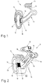
- the bearing devices shown are used to connect female connectors with longitudinal spars 10 of a frame of a slatted frame of a bed or a piece of seating or reclining furniture.
- Opposite end regions of each female connector is a spring means 11 assigned, the spring means 11 are preferably all of the same design.
- the spring means 11 essentially consists of a bearing shell 12, a spring bridge 13 and a bracket 14.
- the bearing bracket 14 of the spring means 11 is assigned to the longitudinal beam 10 of the frame and in the first embodiment is approximately U-shaped and open at the bottom. However, the bearing bracket 14 preferably lies completely against at least some areas the outside of an upper half of the longitudinal spar 10 designed as a hollow profile, whereby the spring means 11 is supported on the longitudinal beam 10.
- the bearing shell 12 is used for Recording an end region of the female connector, not shown, and is approximately U-shaped and trained open to the top.
- the bearing shell 12 and the bracket 14 are connected by the spring bridge 13. Two upper legs 15 of the Spring bridge 13 are attached to the bearing shell 12 on both sides.
- spring bridge 13 Two lower legs 16 the spring bridge 13 are each formed in two parts and connect the upper legs 15 with the bracket 14 bearing shell 12, spring bridge 13 and bracket 14 are preferably formed in one piece from the same material. More details of the Construction of the spring means 11, in particular the spring bridge 13, are the German Patent application DE 198 60 619 A1 can be removed, the content for the purpose of a complete disclosure in full on the content of the present application is made. In this document, the spring means 11 is referred to as a support body.
- a special feature of the spring means 11 is that the bearing bracket 14 on a the longitudinal spar 10 facing the inside holding projections 17 and that the Longitudinal beam 10 in this area with an essentially continuous profile 18 is provided.
- the holding projections 17 correspond to the same ones Wells of the profiling 18 are formed. While in the embodiment shown a plurality, preferably two to four hat projections 17 are also sufficient a single holding projection 17.
- the holding projection 17 is approximately in continuation of the course of the lower legs 16 Bearing bracket 14 arranged and jumps inward in the U-shaped cross section of the Bearing bracket 14 before.
- the bearing bracket lies above and below the retaining projection 17 14 on the outside of the longitudinal spar 10.
- the profile 18 is opposite Outside of the longitudinal spar 10 reset in a cross-section approximately dovetail-shaped recess 19 is arranged.
- the profiling 18 is in the exemplary embodiment shown is a toothed belt, toothed strip or the like, which is arranged in the recess 19 such that the teeth of the holding projection 17 are facing.
- the profiling 18 preferably runs continuously over the entire length of the longitudinal spar 10.
- the profile 18 can also be arranged only in sections in areas in which the spring means 11 to be positioned.
- the holding projections 17 correspond to the teeth of the toothed belt or the like to form the profile 18.
- the holding projection 17 and the profiling 18 serve to lock the spring means 11 on the longitudinal beam 10.
- the spring means 11 is formed from an elastic material and can be positioned on the longitudinal spar 10 in such a way that even when the female connector is not loaded Retaining projection 17 and the profile 18 at least partially in engagement with each other stand. In this way, the female connectors together with the spring means 11 in a desired position on the longitudinal spar 10 can be moved.
- Female connector is the retaining projection 17 via the spring bridge 13 against the profiling 18 pressed and thus the spring means 11 reliably locked on the longitudinal beam 10.
- the holding projection 17 is approximately perpendicular to one through the profiling formed profile plane moves approximately parallel to the adjacent outside of the Longitudinal spar 10 runs. In this position, retaining projection 17 and profiling 18 in Essentially immovable.
- the holding projection 17 and the profiling 18 are disengaged. This can by elastic deformation of at least part of the spring means 10 happen, for example by slightly bending away or swiveling the Bearing bracket 14 from the longitudinal spar 10. The configuration described above in this way allows the slats to be moved without prior Disassembly of the same.
- the female connectors are always connected to the Longitudinal spar 10 are connected, even if retaining projection 17 and profiling 18 are not engaged with each other.
- the holding projection 17 can be designed in this way be that in this case it protrudes into the recess 19, so that the female connectors be guided when moving in the longitudinal direction of the longitudinal spar 10.
- supports can be this longitudinal guide through the contact of the U-shaped bearing bracket 14 on Longitudinal beam 10.
- Another recess 20 for longitudinally displaceable mounting of the Spring means 11 on the longitudinal spar 10 is the first recess 19 opposite to the Arranged outside of the longitudinal spar 10.
- This recess 20 can be used for this purpose with a corresponding projection or a nose on the bracket 14 in engagement stand.
- Fig. 4 shows a further embodiment of a spring means 21.
- a spring means 21 engages in an approximately U-shaped bearing bracket 22 not over the top of the longitudinal spar 10, but in the area of an inside arranged and extends along an upright side surface of the longitudinal spar 23.
- the longitudinal spar 23 is also designed as a hollow profile, but has two inside Chambers 24, 25 are separated from each other by a web 26.
- the spring means 21 preferably a plurality of holding projections 17 in the manner of teeth, with a Profiling 18 on the inside of the longitudinal spar 23 for locking the spring means 21 can be brought into and out of engagement on the longitudinal spar 23.
- the locking of the spring means 21 on the longitudinal spar 23 is, however, essentially not by elastic deformation of the spring means 21, but by pivoting thereof.
- one arranged in the longitudinal direction of the longitudinal spar 23 is preferred continuous recess 27 is provided.
- the recess 27 has an approximately groove-like cross section and is embedded in the area of the top of the longitudinal spar 23.
- lower claw 29 is arranged at the lower free end of the bearing bracket 22, that with a further groove-like depression 30 in the region of the underside of the longitudinal spar 23 corresponds.
- the lower claw 29 and the recess 30 are arranged in this way or designed such that the claw 29 can be detachably latched or clipped into the recess is.
- the spring means 21 on the one hand Longitudinal beam 23 held and on the other hand, the holding projections 17 with the Profiling 18 engaged.
- the profile 18 is preferably as in the above described embodiment formed and arranged.
- To adjust the Spring means 21 is the latching connection between lower claw 29 and recess 30 released by pivoting the spring means 21 around the upper recess 27. there the retaining projections 17 and the profiling 18 disengage, so that the Spring means 21 can be moved in the longitudinal direction of the longitudinal spar 23.
- the Longitudinal guidance of the spring means 21 is through the hinge-like connection of the maintain upper claw 28 with the recess 27.
- the spring means 21 can also be pivoted about the lower claw 29, the latching connection with the longitudinal spar 21 then being established via the upper claw 28 becomes.
- a toothed belt made of a thermoplastic such as PE, PP, POM, ABS, PEI using the residual heat in the production of the Timing belt and / or the longitudinal spar 10, 23 connected to the longitudinal spar 10, 23 becomes.
- the toothed belt can first be produced in an extrusion process.
- the toothed belt is then manufactured in the manner of a pultrusion profile Longitudinal beam 10, 23 used. This process takes place immediately after the production of the Longitudinal spars 10, 23, so that this still has a high temperature due to the manufacturing process.
- the toothed belt is moved over a longer distance along the longitudinal spar 10, 23 out and pressed into the recess 19.
- the toothed belt heats up while it is still warm Longitudinal beam 10, 23 so that the toothed belt softens. With the cooling of the longitudinal spar 10, 23 narrows the recess 19, so that it shrinks and one resulting press connection comes with the timing belt. Additionally results due to the effect of temperature, the thermoplastic becomes bonded of the timing belt with the longitudinal spar 10, 23.
- additional fastening of the toothed belt with the longitudinal spar 10, 23 by gluing, screwing, nailing and / or tacking.
- the invention is also suitable for the production of conductors.
- the along the ladder longitudinal spars are then formed in the manner of the longitudinal spars 10, 13, the have profiles 18 formed from preferably toothed belts.
- the profiles 18 are preferably also arranged in recesses 19.
- the bracket 14 formed connector are the rungs of the ladder at their ends connected to the longitudinal spars.
- the bearing bracket with an up and foldable closing tongue provided so that the bearing bracket in the closed state completely enclose the longitudinal spars, namely ring-like.
Landscapes
- Mattresses And Other Support Structures For Chairs And Beds (AREA)
- Invalid Beds And Related Equipment (AREA)
- Hinges (AREA)
- Springs (AREA)
- Seats For Vehicles (AREA)
- Packaging Of Annular Or Rod-Shaped Articles, Wearing Apparel, Cassettes, Or The Like (AREA)
Applications Claiming Priority (4)
| Application Number | Priority Date | Filing Date | Title |
|---|---|---|---|
| DE10137205 | 2001-08-01 | ||
| DE10137205 | 2001-08-01 | ||
| DE10143400A DE10143400A1 (de) | 2001-08-01 | 2001-09-05 | Lagereinrichtung für Federleisten einer Unterfederung |
| DE10143400 | 2001-09-05 |
Publications (3)
| Publication Number | Publication Date |
|---|---|
| EP1281338A2 true EP1281338A2 (fr) | 2003-02-05 |
| EP1281338A3 EP1281338A3 (fr) | 2004-01-14 |
| EP1281338B1 EP1281338B1 (fr) | 2006-05-10 |
Family
ID=26009819
Family Applications (1)
| Application Number | Title | Priority Date | Filing Date |
|---|---|---|---|
| EP02017293A Expired - Lifetime EP1281338B1 (fr) | 2001-08-01 | 2002-08-01 | Système de palier pour des lattes de sommier |
Country Status (4)
| Country | Link |
|---|---|
| EP (1) | EP1281338B1 (fr) |
| AT (1) | ATE325562T1 (fr) |
| DE (1) | DE50206729D1 (fr) |
| ES (1) | ES2263713T3 (fr) |
Cited By (1)
| Publication number | Priority date | Publication date | Assignee | Title |
|---|---|---|---|---|
| WO2004021841A1 (fr) * | 2002-08-17 | 2004-03-18 | Daimlerchrysler Ag | Couchette pour une cabine de chauffeur |
Citations (1)
| Publication number | Priority date | Publication date | Assignee | Title |
|---|---|---|---|---|
| DE19860619A1 (de) | 1998-01-09 | 1999-07-15 | Thomas Beteil & Vermoeg Gmbh | Stützkörper für Federleisten einer Unterfederung von insbesondere Sitz- und Liegemöbeln |
Family Cites Families (2)
| Publication number | Priority date | Publication date | Assignee | Title |
|---|---|---|---|---|
| DE8805305U1 (de) * | 1988-04-21 | 1988-06-01 | Kamps, Heinz, 4180 Goch | Bettrahmen |
| IT1296919B1 (it) * | 1997-12-04 | 1999-08-03 | Esperides Srl | Struttura elastica per piani letto a doghe |
-
2002
- 2002-08-01 DE DE50206729T patent/DE50206729D1/de not_active Expired - Lifetime
- 2002-08-01 AT AT02017293T patent/ATE325562T1/de not_active IP Right Cessation
- 2002-08-01 EP EP02017293A patent/EP1281338B1/fr not_active Expired - Lifetime
- 2002-08-01 ES ES02017293T patent/ES2263713T3/es not_active Expired - Lifetime
Patent Citations (1)
| Publication number | Priority date | Publication date | Assignee | Title |
|---|---|---|---|---|
| DE19860619A1 (de) | 1998-01-09 | 1999-07-15 | Thomas Beteil & Vermoeg Gmbh | Stützkörper für Federleisten einer Unterfederung von insbesondere Sitz- und Liegemöbeln |
Cited By (1)
| Publication number | Priority date | Publication date | Assignee | Title |
|---|---|---|---|---|
| WO2004021841A1 (fr) * | 2002-08-17 | 2004-03-18 | Daimlerchrysler Ag | Couchette pour une cabine de chauffeur |
Also Published As
| Publication number | Publication date |
|---|---|
| EP1281338B1 (fr) | 2006-05-10 |
| ATE325562T1 (de) | 2006-06-15 |
| ES2263713T3 (es) | 2006-12-16 |
| EP1281338A3 (fr) | 2004-01-14 |
| DE50206729D1 (de) | 2006-06-14 |
Similar Documents
| Publication | Publication Date | Title |
|---|---|---|
| DE69907471T2 (de) | Kraftfahrzeugscheibenwischer | |
| DE2435147B2 (de) | Aus teilweise abgebogenen profilstangen gebildetes gestell | |
| DE60210992T2 (de) | Vorrichtung zur Befestigung einer Federleiste an den Rahmen eines Lattenrosts | |
| DE4210556A1 (de) | Einrichtung zum Befestigen elektrischer Installationsgeräte auf Tragschienen | |
| DE60015511T2 (de) | Höhenverstellvorrichtung, insbesondere für rückenlehne und armstütze von bürostühlen | |
| DE3716917C2 (de) | Aufstellbeschlag für einen Liegerahmen | |
| DE2411414C2 (de) | Vorrichtung zum Arretieren der Gleitschienen eines verstellbaren Sitzes, insbesondere eines Fahrzeugsitzes | |
| DE3213847A1 (de) | Traggestell | |
| DE29611876U1 (de) | Endfeder zur gefederten Lagerung von Latten eines Lattenrostes | |
| EP0445325B1 (fr) | Sommier | |
| AT395133B (de) | Tragleiste fuer einen fahrzeug-gepaeckstraeger | |
| EP1281338B1 (fr) | Système de palier pour des lattes de sommier | |
| DE3540040C2 (fr) | ||
| EP0111679B1 (fr) | Banc de jardin avec deux pieds portant le siège et le dossier | |
| EP3636104A2 (fr) | Dispositif d'accouplement pour le guidage de coulisse | |
| DE19612079A1 (de) | Kopf- oder Fußstütze für Lattenrostliegen und Lattenrostauflage dafür | |
| DE10143400A1 (de) | Lagereinrichtung für Federleisten einer Unterfederung | |
| DE3716714C2 (fr) | ||
| DE102019110208B4 (de) | Mikrolineare laufschienenmontage und deren gleiter | |
| EP0479122B1 (fr) | Dispositif anti-éblouissement | |
| DE202004004703U1 (de) | Rahmen für eine Tür, ein Fenster o.dgl. | |
| DE19852133A1 (de) | Abstandshalter | |
| DE9215337U1 (de) | Schublade | |
| EP0394733B1 (fr) | Dispositif de positionnement pour un support de tête ou de pied | |
| DE19729442B4 (de) | Stapelsäule |
Legal Events
| Date | Code | Title | Description |
|---|---|---|---|
| PUAI | Public reference made under article 153(3) epc to a published international application that has entered the european phase |
Free format text: ORIGINAL CODE: 0009012 |
|
| AK | Designated contracting states |
Designated state(s): AT BE BG CH CY CZ DE DK EE ES FI FR GB GR IE IT LI LU MC NL PT SE SK TR |
|
| AX | Request for extension of the european patent |
Extension state: AL LT LV MK RO SI |
|
| PUAL | Search report despatched |
Free format text: ORIGINAL CODE: 0009013 |
|
| AK | Designated contracting states |
Kind code of ref document: A3 Designated state(s): AT BE BG CH CY CZ DE DK EE ES FI FR GB GR IE IT LI LU MC NL PT SE SK TR |
|
| AX | Request for extension of the european patent |
Extension state: AL LT LV MK RO SI |
|
| 17P | Request for examination filed |
Effective date: 20040712 |
|
| AKX | Designation fees paid |
Designated state(s): AT BE BG CH CY CZ DE DK EE ES FI FR GB GR IE IT LI LU MC NL PT SE SK TR |
|
| 17Q | First examination report despatched |
Effective date: 20041018 |
|
| GRAP | Despatch of communication of intention to grant a patent |
Free format text: ORIGINAL CODE: EPIDOSNIGR1 |
|
| GRAS | Grant fee paid |
Free format text: ORIGINAL CODE: EPIDOSNIGR3 |
|
| GRAA | (expected) grant |
Free format text: ORIGINAL CODE: 0009210 |
|
| AK | Designated contracting states |
Kind code of ref document: B1 Designated state(s): AT BE BG CH CY CZ DE DK EE ES FI FR GB GR IE IT LI LU MC NL PT SE SK TR |
|
| PG25 | Lapsed in a contracting state [announced via postgrant information from national office to epo] |
Ref country code: IT Free format text: LAPSE BECAUSE OF FAILURE TO SUBMIT A TRANSLATION OF THE DESCRIPTION OR TO PAY THE FEE WITHIN THE PRESCRIBED TIME-LIMIT;WARNING: LAPSES OF ITALIAN PATENTS WITH EFFECTIVE DATE BEFORE 2007 MAY HAVE OCCURRED AT ANY TIME BEFORE 2007. THE CORRECT EFFECTIVE DATE MAY BE DIFFERENT FROM THE ONE RECORDED. Effective date: 20060510 Ref country code: NL Free format text: LAPSE BECAUSE OF FAILURE TO SUBMIT A TRANSLATION OF THE DESCRIPTION OR TO PAY THE FEE WITHIN THE PRESCRIBED TIME-LIMIT Effective date: 20060510 Ref country code: SK Free format text: LAPSE BECAUSE OF FAILURE TO SUBMIT A TRANSLATION OF THE DESCRIPTION OR TO PAY THE FEE WITHIN THE PRESCRIBED TIME-LIMIT Effective date: 20060510 Ref country code: FI Free format text: LAPSE BECAUSE OF FAILURE TO SUBMIT A TRANSLATION OF THE DESCRIPTION OR TO PAY THE FEE WITHIN THE PRESCRIBED TIME-LIMIT Effective date: 20060510 Ref country code: IE Free format text: LAPSE BECAUSE OF FAILURE TO SUBMIT A TRANSLATION OF THE DESCRIPTION OR TO PAY THE FEE WITHIN THE PRESCRIBED TIME-LIMIT Effective date: 20060510 Ref country code: CZ Free format text: LAPSE BECAUSE OF FAILURE TO SUBMIT A TRANSLATION OF THE DESCRIPTION OR TO PAY THE FEE WITHIN THE PRESCRIBED TIME-LIMIT Effective date: 20060510 |
|
| REG | Reference to a national code |
Ref country code: GB Ref legal event code: FG4D Free format text: NOT ENGLISH |
|
| REG | Reference to a national code |
Ref country code: CH Ref legal event code: EP |
|
| REF | Corresponds to: |
Ref document number: 50206729 Country of ref document: DE Date of ref document: 20060614 Kind code of ref document: P |
|
| REG | Reference to a national code |
Ref country code: IE Ref legal event code: FG4D Free format text: LANGUAGE OF EP DOCUMENT: GERMAN |
|
| PG25 | Lapsed in a contracting state [announced via postgrant information from national office to epo] |
Ref country code: SE Free format text: LAPSE BECAUSE OF FAILURE TO SUBMIT A TRANSLATION OF THE DESCRIPTION OR TO PAY THE FEE WITHIN THE PRESCRIBED TIME-LIMIT Effective date: 20060810 Ref country code: DK Free format text: LAPSE BECAUSE OF FAILURE TO SUBMIT A TRANSLATION OF THE DESCRIPTION OR TO PAY THE FEE WITHIN THE PRESCRIBED TIME-LIMIT Effective date: 20060810 |
|
| PG25 | Lapsed in a contracting state [announced via postgrant information from national office to epo] |
Ref country code: MC Free format text: LAPSE BECAUSE OF NON-PAYMENT OF DUE FEES Effective date: 20060831 Ref country code: BE Free format text: LAPSE BECAUSE OF NON-PAYMENT OF DUE FEES Effective date: 20060831 Ref country code: CH Free format text: LAPSE BECAUSE OF NON-PAYMENT OF DUE FEES Effective date: 20060831 Ref country code: LI Free format text: LAPSE BECAUSE OF NON-PAYMENT OF DUE FEES Effective date: 20060831 |
|
| GBT | Gb: translation of ep patent filed (gb section 77(6)(a)/1977) |
Effective date: 20060904 |
|
| PG25 | Lapsed in a contracting state [announced via postgrant information from national office to epo] |
Ref country code: PT Free format text: LAPSE BECAUSE OF FAILURE TO SUBMIT A TRANSLATION OF THE DESCRIPTION OR TO PAY THE FEE WITHIN THE PRESCRIBED TIME-LIMIT Effective date: 20061010 |
|
| NLV1 | Nl: lapsed or annulled due to failure to fulfill the requirements of art. 29p and 29m of the patents act | ||
| REG | Reference to a national code |
Ref country code: ES Ref legal event code: FG2A Ref document number: 2263713 Country of ref document: ES Kind code of ref document: T3 |
|
| ET | Fr: translation filed | ||
| REG | Reference to a national code |
Ref country code: IE Ref legal event code: FD4D |
|
| PLBE | No opposition filed within time limit |
Free format text: ORIGINAL CODE: 0009261 |
|
| STAA | Information on the status of an ep patent application or granted ep patent |
Free format text: STATUS: NO OPPOSITION FILED WITHIN TIME LIMIT |
|
| REG | Reference to a national code |
Ref country code: CH Ref legal event code: PL |
|
| 26N | No opposition filed |
Effective date: 20070213 |
|
| PG25 | Lapsed in a contracting state [announced via postgrant information from national office to epo] |
Ref country code: AT Free format text: LAPSE BECAUSE OF NON-PAYMENT OF DUE FEES Effective date: 20060801 |
|
| BERE | Be: lapsed |
Owner name: THOMAS G.M.B.H. + CO. TECHNIK + INNOVATION KG Effective date: 20060831 |
|
| PG25 | Lapsed in a contracting state [announced via postgrant information from national office to epo] |
Ref country code: GR Free format text: LAPSE BECAUSE OF FAILURE TO SUBMIT A TRANSLATION OF THE DESCRIPTION OR TO PAY THE FEE WITHIN THE PRESCRIBED TIME-LIMIT Effective date: 20060811 |
|
| PG25 | Lapsed in a contracting state [announced via postgrant information from national office to epo] |
Ref country code: BG Free format text: LAPSE BECAUSE OF FAILURE TO SUBMIT A TRANSLATION OF THE DESCRIPTION OR TO PAY THE FEE WITHIN THE PRESCRIBED TIME-LIMIT Effective date: 20060810 Ref country code: EE Free format text: LAPSE BECAUSE OF FAILURE TO SUBMIT A TRANSLATION OF THE DESCRIPTION OR TO PAY THE FEE WITHIN THE PRESCRIBED TIME-LIMIT Effective date: 20060510 |
|
| PG25 | Lapsed in a contracting state [announced via postgrant information from national office to epo] |
Ref country code: LU Free format text: LAPSE BECAUSE OF NON-PAYMENT OF DUE FEES Effective date: 20060801 Ref country code: TR Free format text: LAPSE BECAUSE OF FAILURE TO SUBMIT A TRANSLATION OF THE DESCRIPTION OR TO PAY THE FEE WITHIN THE PRESCRIBED TIME-LIMIT Effective date: 20060510 |
|
| PG25 | Lapsed in a contracting state [announced via postgrant information from national office to epo] |
Ref country code: CY Free format text: LAPSE BECAUSE OF FAILURE TO SUBMIT A TRANSLATION OF THE DESCRIPTION OR TO PAY THE FEE WITHIN THE PRESCRIBED TIME-LIMIT Effective date: 20060510 |
|
| PGFP | Annual fee paid to national office [announced via postgrant information from national office to epo] |
Ref country code: ES Payment date: 20100915 Year of fee payment: 9 |
|
| PGFP | Annual fee paid to national office [announced via postgrant information from national office to epo] |
Ref country code: DE Payment date: 20100821 Year of fee payment: 9 Ref country code: FR Payment date: 20100824 Year of fee payment: 9 |
|
| PGFP | Annual fee paid to national office [announced via postgrant information from national office to epo] |
Ref country code: GB Payment date: 20100728 Year of fee payment: 9 |
|
| GBPC | Gb: european patent ceased through non-payment of renewal fee |
Effective date: 20110801 |
|
| REG | Reference to a national code |
Ref country code: FR Ref legal event code: ST Effective date: 20120430 |
|
| REG | Reference to a national code |
Ref country code: DE Ref legal event code: R119 Ref document number: 50206729 Country of ref document: DE Effective date: 20120301 |
|
| PG25 | Lapsed in a contracting state [announced via postgrant information from national office to epo] |
Ref country code: FR Free format text: LAPSE BECAUSE OF NON-PAYMENT OF DUE FEES Effective date: 20110831 Ref country code: GB Free format text: LAPSE BECAUSE OF NON-PAYMENT OF DUE FEES Effective date: 20110801 |
|
| REG | Reference to a national code |
Ref country code: ES Ref legal event code: FD2A Effective date: 20121207 |
|
| PG25 | Lapsed in a contracting state [announced via postgrant information from national office to epo] |
Ref country code: ES Free format text: LAPSE BECAUSE OF NON-PAYMENT OF DUE FEES Effective date: 20110802 |
|
| PG25 | Lapsed in a contracting state [announced via postgrant information from national office to epo] |
Ref country code: DE Free format text: LAPSE BECAUSE OF NON-PAYMENT OF DUE FEES Effective date: 20120301 |