EP1281527A2 - Flüssigkeitsausstossaufzeichnungsgerät - Google Patents
Flüssigkeitsausstossaufzeichnungsgerät Download PDFInfo
- Publication number
- EP1281527A2 EP1281527A2 EP02024197A EP02024197A EP1281527A2 EP 1281527 A2 EP1281527 A2 EP 1281527A2 EP 02024197 A EP02024197 A EP 02024197A EP 02024197 A EP02024197 A EP 02024197A EP 1281527 A2 EP1281527 A2 EP 1281527A2
- Authority
- EP
- European Patent Office
- Prior art keywords
- ink
- tank
- liquid
- supply
- head
- Prior art date
- Legal status (The legal status is an assumption and is not a legal conclusion. Google has not performed a legal analysis and makes no representation as to the accuracy of the status listed.)
- Granted
Links
Images




Classifications
-
- B—PERFORMING OPERATIONS; TRANSPORTING
- B41—PRINTING; LINING MACHINES; TYPEWRITERS; STAMPS
- B41J—TYPEWRITERS; SELECTIVE PRINTING MECHANISMS, i.e. MECHANISMS PRINTING OTHERWISE THAN FROM A FORME; CORRECTION OF TYPOGRAPHICAL ERRORS
- B41J2/00—Typewriters or selective printing mechanisms characterised by the printing or marking process for which they are designed
- B41J2/005—Typewriters or selective printing mechanisms characterised by the printing or marking process for which they are designed characterised by bringing liquid or particles selectively into contact with a printing material
- B41J2/01—Ink jet
- B41J2/17—Ink jet characterised by ink handling
- B41J2/175—Ink supply systems ; Circuit parts therefor
- B41J2/17503—Ink cartridges
- B41J2/17513—Inner structure
-
- B—PERFORMING OPERATIONS; TRANSPORTING
- B41—PRINTING; LINING MACHINES; TYPEWRITERS; STAMPS
- B41J—TYPEWRITERS; SELECTIVE PRINTING MECHANISMS, i.e. MECHANISMS PRINTING OTHERWISE THAN FROM A FORME; CORRECTION OF TYPOGRAPHICAL ERRORS
- B41J2/00—Typewriters or selective printing mechanisms characterised by the printing or marking process for which they are designed
- B41J2/005—Typewriters or selective printing mechanisms characterised by the printing or marking process for which they are designed characterised by bringing liquid or particles selectively into contact with a printing material
- B41J2/01—Ink jet
- B41J2/17—Ink jet characterised by ink handling
- B41J2/175—Ink supply systems ; Circuit parts therefor
-
- B—PERFORMING OPERATIONS; TRANSPORTING
- B41—PRINTING; LINING MACHINES; TYPEWRITERS; STAMPS
- B41J—TYPEWRITERS; SELECTIVE PRINTING MECHANISMS, i.e. MECHANISMS PRINTING OTHERWISE THAN FROM A FORME; CORRECTION OF TYPOGRAPHICAL ERRORS
- B41J2/00—Typewriters or selective printing mechanisms characterised by the printing or marking process for which they are designed
- B41J2/005—Typewriters or selective printing mechanisms characterised by the printing or marking process for which they are designed characterised by bringing liquid or particles selectively into contact with a printing material
- B41J2/01—Ink jet
- B41J2/17—Ink jet characterised by ink handling
- B41J2/175—Ink supply systems ; Circuit parts therefor
- B41J2/17503—Ink cartridges
- B41J2/1752—Mounting within the printer
- B41J2/17523—Ink connection
-
- B—PERFORMING OPERATIONS; TRANSPORTING
- B41—PRINTING; LINING MACHINES; TYPEWRITERS; STAMPS
- B41J—TYPEWRITERS; SELECTIVE PRINTING MECHANISMS, i.e. MECHANISMS PRINTING OTHERWISE THAN FROM A FORME; CORRECTION OF TYPOGRAPHICAL ERRORS
- B41J2/00—Typewriters or selective printing mechanisms characterised by the printing or marking process for which they are designed
- B41J2/005—Typewriters or selective printing mechanisms characterised by the printing or marking process for which they are designed characterised by bringing liquid or particles selectively into contact with a printing material
- B41J2/01—Ink jet
- B41J2/17—Ink jet characterised by ink handling
- B41J2/175—Ink supply systems ; Circuit parts therefor
- B41J2/17566—Ink level or ink residue control
-
- B—PERFORMING OPERATIONS; TRANSPORTING
- B41—PRINTING; LINING MACHINES; TYPEWRITERS; STAMPS
- B41J—TYPEWRITERS; SELECTIVE PRINTING MECHANISMS, i.e. MECHANISMS PRINTING OTHERWISE THAN FROM A FORME; CORRECTION OF TYPOGRAPHICAL ERRORS
- B41J2/00—Typewriters or selective printing mechanisms characterised by the printing or marking process for which they are designed
- B41J2/005—Typewriters or selective printing mechanisms characterised by the printing or marking process for which they are designed characterised by bringing liquid or particles selectively into contact with a printing material
- B41J2/01—Ink jet
- B41J2/21—Ink jet for multi-colour printing
- B41J2/2107—Ink jet for multi-colour printing characterised by the ink properties
- B41J2/2114—Ejecting specialized liquids, e.g. transparent or processing liquids
Definitions
- the present invention relates to a liquid supplying method for eventually supplying liquid to a liquid ejection head and to a liquid supplying device.
- the present invention relates to a system for supplying a liquid frequently used and to an ink jet recording apparatus equipped therewith.
- a recording head provided in an ink jet recording apparatus of this type can be mounted on a carriage which is fixed or reciprocated in a plane parallel to the recording material and in a direction perpendicular to the feeding direction of the recording material.
- the carriage is moved in a straight line by a predetermined command and, at the same time, ink droplets are ejected from the recording head in response to a predetermined signal to effect recording, and then the recording material is fed by a predetermined amount by a feeding device. These operations are repeated.
- the surface of the recording head on which ejection outlets are formed is capped to thereby effect a suction recovery operation, thereby keeping the ejecting section in the normal state.
- the above-described recording head which consumes ink when forming images, has to be constantly supplied with ink.
- an ink tank is provided at a position separate from the carriage and connected to the recording head through a tube.
- ink is supplied to the recording head by utilizing the head difference between the head and the ink tank.
- a head cartridge in which a negative pressure is generated in the ink tank with respect to the recording head to thereby detachably mount the ink tank on the carriage, forming the recording head and the ink tank as an integral unit.
- a head cartridge can be classified into two types: in one type, the recording head and the ink tank are constantly in an integrated state. In the other type, the recording head and the ink tank are formed as separate components, and both can be separated from the recording apparatus, the two components being united together when used.
- the ink tank includes a porous member such as a sponge accommodated for the purpose of storing ink and an atmospheric air communication opening for making it possible to take atmospheric air in the ink accommodating section to smooth the ink being used for printing.
- Fig. 14 is a schematic sectional view showing an ink tank of the above-described construction.
- the interior of an ink tank 101 is divided into two spaces by a partition 103 having a communication hole 102.
- One space constitutes an ink accommodating chamber 104 which is tightly closed except for the communication hole 102 and which holds ink as it is without allowing it to come into contact with any other component.
- the other space constitutes an ink holding member accommodating chamber (atmosphere-communicating type liquid accommodating chamber) 106 for accommodating an ink holding member 105.
- an atmosphere-communication opening 107 for introducing atmospheric air as the ink is consumed, and a supply opening 108 for supplying ink to the recording head section.
- FIG. 1 Another known ink supply system is a so-called pit-in system, in which a large-capacity tank for holding ink (hereinafter referred to as a "large tank”) is provided and in which a head cartridge on which an ink tank and a recording head are integrally mounted is mounted on a carriage.
- the carriage is moved and the ink tank of the head cartridge (hereinafter referred to as the "tank section") is connected to the large tank at a predetermined position, whereby ink supply is effected.
- the ink tank constituting the tank section need not be replaced.
- the large tank it is generally supplied with ink when all the ink therein has been consumed.
- the former measure will lead to an increase in the size of the apparatus or waste of ink, and the latter measure will lead to an increase in non-recording period with the increase in the number of times that the ink supply is effected, resulting in a reduction in throughput.
- the present invention has been made with a view toward solving the above problems in the prior art from a completely different point of view. It is a first object of the present invention to provide an ink supply system which can eliminate the above problems with a simple construction.
- the effect of fixing the color agent of the ink to the recording material is enhanced by processing the entire surface of the recording material with a processing liquid (hereinafter referred to as the "preprocessing liquid").
- a processing liquid chemically reacts with the ink pigment to form insoluble matter (agents utilizing anion/cation reaction are known), so that, if the preprocessing liquid tank is connected with other tanks by erroneous operation, solidification will occur as a result of chemical reaction between the liquids, with the result that the ink tank, or in the worst case, even the recording head, become of no use.
- some measures must be taken to avoid color-mixing/liquid-mixing by erroneous operation.
- the present invention provides a liquid supplying method for a liquid ejection head of the type which uses an atmosphere communicating type liquid accommodating container filled with a negative pressure generating member to supply a liquid to a liquid ejection head, wherein there is provided a liquid holding container communicating with the bottom section of the atmosphere communicating type liquid accommodating container, the amount of liquid supplied to the liquid holding container being controlled on the basis of a judgment regarding the liquid holding condition of the liquid holding container.
- the present invention also provides, in addition to or apart from the above construction, an erroneous supply preventing mechanism which helps to prevent erroneous supply of different liquids between a plurality of large tanks and the tank sections of a plurality of head cartridges.
- the above-described erroneous supply preventing mechanism prevents a large tank and a tank section of different liquids from being connected even in the case of erroneous operation, so that no color-mixing/liquid-mixing is generated.
- a liquid ejection recording apparatus which adopts the pit-in system to reduce the number of times that the frequently used ink tank on the carriage is replaced, which prevents different liquids from being erroneously supplied, and which realizes a stable liquid supply to the recording head.
- the tank section is formed as an integral tank composed of a liquid holding chamber which is practically sealed at least when ink is supplied and when ink is consumed and an atmosphere communicating type liquid accommodating chamber filled with an ink holding member having a negative pressure generating function, the liquid holding chamber and the atmosphere communicating type liquid accommodating chamber being separated from each other by a partition and communicating with each other only through a communication hole provided in the partition, the liquid holding chamber of the integral tank and the large tank being connected to each other at the time of liquid supply, whereby a stable ink supply can be advantageously realized.
- the tank section of the head cartridge is formed as an integral tank composed of a preparatory chamber for temporarily holding liquid from the large tank at the time of liquid supply, an atmosphere communicating type liquid accommodating chamber filled with an ink holding member having a negative pressure generating function, and a partition which allows the preparatory chamber and the atmosphere communicating type liquid accommodating chamber to communicated with each other only through a communication hole, an opening being provided in the preparatory chamber of the integral tank so that the integral tank and the large tank are connected to each other through this opening at the time of liquid supply.
- a liquid ejection recording apparatus of the type in which a plurality of head-tank sets of each consisting of an ink jet recording head and an ink tank connected thereto or a plurality of head cartridges each consisting of a recording head and an ink tank united together into an integral unit are mounted and arranged on a carriage capable of moving relative to a recording material to form color images on the recording material, wherein, of the ink tanks, a particular ink tank having relatively large capacity has an ink receiving mechanism, the particular ink tank being supplied with ink at a predetermined position by supplying means.
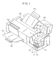
- Fig. 1 is a schematic perspective view showing a color printer constituting a liquid ejection apparatus according to an embodiment of the present invention.
- an operating panel 112 is provided on the front portion of the upper surface of the housing of an liquid ejection recording apparatus (color printer) 111.
- Numeral 113 indicates a paper feeding tray for holding paper (recording medium) before recording;
- numeral 114 indicates a sheet of paper discharged through a paper feeding path inside the printer 111; and
- numeral 115 indicates a paper discharge tray for holding the sheet of paper 114.
- Numeral 116 indicates a main body cover which covers an opening 117 formed in the right front portion of the housing. The main body cover is rotatably mounted at the inner end of the opening 117 by a hinge 118. Further, a carriage 119 supported by a guide or the like (not shown) is arranged inside the housing.
- the carriage 119 is provided so as to be capable of reciprocating in the width direction of the sheet of paper passing the above-mentioned paper feeding path.
- head cartridges (1a, 1b 1c and ld) each consisting of an integral unit of a head and each of ink tanks for accommodating inks of black (B), cyan (C), magenta (M) and yellow (Y), respectively.
- Numeral 2 indicates a large tank for black ink, which is supplied to the head cartridge 1a by a supply method described below.
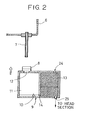
- Fig. 2 is a schematic diagram illustrating the connection and supply between the large tank and the tank section in a first embodiment of the present invention.
- an inlet 12 through which a supply needle 7 of a large tank 6 holding liquid is inserted is provided in a wall forming an ink accommodating chamber 11 of a tank section 9 of a head cartridge for accommodating a frequently used liquid.
- This inlet 12 is tightly sealed by a double valve mechanism 8 for preventing the ink accommodating chamber 11 from communicating with the atmosphere at the time of insertion of the needle.
- An ink holding member accommodating chamber 13 is provided with an atmosphere communicating opening 24 and an ink supply outlet 25 for supplying ink to the recording head.
- the insertion of the supply tube 7 into the inlet 12 is effected when the tank section 9 moves to the large tank 6 side through the movement of the head cartridge. At this time, the supply tube 7 is inserted into the inlet 12 through the double valve mechanism 8, so that the ink accommodating chamber 11 can always be kept in a sealed state without communicating with the atmosphere.
- the double valve mechanism 8 consists of a first valve chamber (not shown) and a second valve chamber (not shown). When the forward end of the supply needle 7 enters the first valve chamber 1, the second valve chamber, which communicates with the ink accommodating chamber, is closed, the forward end of the needle being only allowed to enter the second valve chamber after the sealing with the first chamber has been secured.
- the remaining amount of ink in the ink accommodating chamber 11 is monitored by an optical level detector 10 provided at the bottom of the ink accommodating chamber 11.
- an optical level detector 10 provided at the bottom of the ink accommodating chamber 11.
- the optical level detector 10 is provided at the bottom of the ink accommodating chamber 11, this should not be construed restrictively. It is also possible to judge the level of the ink accommodating chamber 11 from the amount of liquid consumed by the recording head and supply the requisite amount of ink. For example, the number of droplets (dots) ejected from the recording head which makes the ink accommodating chamber 11 completely empty may be ascertained beforehand, and the control unit may be provided with a set value obtained by adding a safety value to this dot count value to prevent the ink accommodating chamber 11 from becoming completely empty, supplying an amount of liquid corresponding to the set value whenever this set value is reached. This arrangement helps to minimize the requisite time for liquid supply. Further, when the tank section of the head cartridge adopts a partial tank structure, the liquid supply to the recording head is stabilized.
- a slide plate 27 and an ink supply tube 26 as shown in Fig. 3 to seal the ink accommodating chamber at the time of ink supply and ink consumption.
- Any opening/closing mechanism will serve the purpose as long as this action is possible. In this case, even if the ink accommodating chamber is opened to the atmosphere during the connecting operation, the opening period is very short, so that, even if some liquid flows to the ink holding member side, it is sufficiently possible for the liquid to be held by the ink holding member, whereby it is possible to prevent ink from being inadvertently flowing out of the recording head.
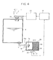
- Fig. 4 is a schematic diagram showing a system for supplying ink from a large tank to a tank section accommodating ink holding member according to a second embodiment of the present invention.
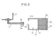
- Fig. 5 is a diagram illustrating the condition in which the supply needle of the large tank is not inserted into the inlet of the tank section.
- This second embodiment differs from the above-described first embodiment in that the portion corresponding to the ink accommodating chamber of the first embodiment (hereinafter referred to as a "preparatory chamber”) is a system open to the atmosphere during the consumption of liquid by the recording head.
- the tank section is composed of an ink holding member accommodating chamber 30 and a preparatory chamber 31, the ink holding member accommodating chamber 30 communicating with the preparatory chamber 31 through a communicating section 17 at the bottom.
- the ink holding member accommodating chamber has an atmosphere communicating opening 28 and an ink supply outlet 29 and contains an ink holding member. It is only necessary for the preparatory chamber 31 to have a function by which it temporarily holds ink to be supplied to the absorbing member holding chamber equipped with an ink absorbing member at the time of liquid supply described below.
- an inlet 19a is provided, whereby the chamber is made open to the atmosphere.
- the large tank has an atmosphere communicating opening 6a, which is normally closed by a valve body 23.
- a supply needle 7 for supplying liquid to the preparatory chamber of the tank section is connected to the bottom of the large tank.
- the supply opening 7a at the forward end of the supply needle is closed by a sealing section 18 when it is not connected to the tank section, whereby leakage of ink from the forward end of the needle is prevented.
- the insertion of the supply needle 7 into the inlet 19a is effected by moving the tank section to the large tank side by moving the head cartridge. At this time, when the sealing section 18 abuts the inlet 19a, the sealing section is retained there and only the supply needle 7 is inserted into the preparatory chamber, so that the supply opening 7a is reliably opened within the preparatory chamber.
- iron is used on the side of the sealing section 18 abutting the tank section
- a magnet or the like is used on the side of the tank section abutting the sealing section.
- the amount of ink in the preparatory chamber of the tank section 19 is monitored by an optical sensor 20.
- a control unit 21 permits ink supply in a sequence described below according to the detecting result of this sensor, a valve body driving device 22 is driven by a command from the control unit 21, and the valve body 23 closing the atmosphere communicating hole 6a of the large tank 6 is opened for a fixed period of time, whereby a fixed amount of ink is supplied from the supply opening 7a at the forward end of the supply needle 7 to the preparatory chamber 31 of the tank section 19.
- the ink thus supplied is supplied to the ink holding member accommodating chamber 30 from the preparatory chamber 31 through the communicating hole 17. Since the communicating hole 17 is at the bottom of the container having the ink supply outlet 29 leading to the head section, it is possible to directly supply ink to the remaining ink in the ink absorbing member, thereby making it possible to prevent air from intruding the recording head (not shown). Further, when, as in this embodiment, the communicating hole 17 is arranged at a position spaced apart from the ink supply outlet 29 leading to the head section, little air is allowed to enter the recording head side during printing operation, whereby it is advantageously possible to perform a more stable printing.
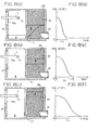
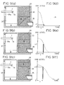
- Figs. 8A through 8F and Figs. 9A through 9F are diagrams illustrating a method of detecting the liquid accommodating amount of the tank section in the connection and supply between the large tank and the tank section according to the second embodiment of the present invention.
- numeral 35 indicates an ink supply duct for supplying ink to the recording head section (not shown).
- a passage capable of introducing air.
- Figs. 8A through 8C and Figs. 9A through 9C the variation in level of the preparatory chamber 31 and the ink holding member accommodating chamber is indicated by solid lines and arrows.
- Fig. 8 in the liquid supply operation mentioned above, a predetermined amount of ink is supplied from the large tank to the preparatory chamber 31, and absorbed by the ink holding member through the communication hole 17.
- Figs. 8A through 8F show the relationship between the level of the ink holding member and the change with time in the amount of ink in the preparatory chamber 31 during this operation. That is, when the level of the ink holding member changes from that of Fig. 8A to that of Fig. 8C, the amount of ink in the preparatory chamber 31 undergoes a change with time as shown in Figs. 8D through 8F.
- the negative pressure generating power of the ink holding member is large, so that ink is sucked up with a large force, the ink moving to the ink holding member in a short time (ta) as shown in Fig. 8D.
- the negative pressure generating power of the ink holding member is small, so that ink is sucked up with a small force, the ink moving to the ink holding member in a longer time (tc) as shown in Fig. 8F.
- the time it takes for the ink to be sucked up varies in accordance with the level of the ink holding member.
- the time it takes for the ink to be removed from the preparatory chamber is detected by using an optical sensor provided in the vicinity of the communication hole at the bottom of the preparatory chamber, whereby the level of the ink holding member is detected and the control unit makes a judgment as to whether a predetermined amount of ink can be supplied again or not. That is, when the time it takes for the ink to be sucked up is short, a command to permit the supply of a predetermined amount of ink again is issued, and when the time it takes for the ink to be sucked up is long, a command to prohibit the supply of a predetermined amount of ink again is issued.
- the remaining amount of ink after the predetermined time (v3) is large as shown in Fig. 9F.
- the amount of ink in the preparatory chamber can be judged, for example, through measurement of the voltage of the light receiving section of the optical sensor and comparison of the values measured.
- the timing with which the ink supplying operation is to be started can be determined by judging the remaining amount of ink in the in holding member accommodating chamber from the amount of liquid consumed by the recording head. For example, the number of droplets (dots) ejected from the recording head which causes the liquid in the ink holding member accommodating chamber to be completely used up is checked beforehand, and a safety value which helps to prevent the ink holding member accommodating chamber from becoming completely empty is added to this dot count value.
- the set value thus obtained is provided in the control unit for supply operation (not shown), the supply operation being started whenever this set value is reached.
- Figs. 6A, 6B, 7A and 7B are diagrams illustrating other examples of the inlet of the tank section of the second embodiment of the present invention, of which Figs. 6A and 7A show the condition before the connection with the supply needle of the large tank; and Figs. 6B and 7B show the condition after the connection.
- a part of the inlet 19 is or the valve mechanism is formed of an elastic material such as rubber, so that, when the supply needle is inserted, it flexibly opens and, when the needle is taken out, the major portion of the opening is closed.
- the preparatory chamber becomes open to the atmosphere.
- the liquid supply is not conducted, it is desirable, from the viewpoint of reducing ink evaporation through the communication hole from the preparatory chamber to the absorbing member accommodating chamber, it is more desirable for the opening portion to be small as shown in Fig. 6 or to provide a valve mechanism as shown in Fig. 7 to form a closed state when liquid supply is not effected than to provide a large opening portion as shown in Fig. 5.
- the absorbing member holding chamber with a buffer function for preventing ink leakage or to provide the preparatory chamber with a one-way valve or the like for dissipating the pressure in the preparatory chamber in order to cope with the expansion of the air in the preparatory chamber due to a rise in the environmental temperature.
- Figs. 10A and 10B are diagrams illustrating other examples of the liquid detecting device used in the second embodiment of the present invention.
- the bottom section 32 of the preparatory chamber 31 is inclined and made transparent to thereby make it possible to detect the difference in the reflection amount by an optical sensor 33 according to the presence of ink.
- the bottom section 32 of the preparatory chamber is inclined toward the communication hole 17, whereby the ink in the preparatory chamber 31 can be reliably absorbed by the ink holding member.
- a pair of electrodes 34 are provided in the vicinity of the communication hole instead of the optical sensor.
- the liquid is directly supplied to the liquid holding chamber or the preparatory chamber, so that the requisite time for liquid supply is relatively short. Further, either method is applicable not only to the case of the pit-in system but also to the case, for example, in which the tank section of the head cartridge and the large tank are directly connected to each other through a tube.
- a one-way valve or the like is provided in the tube connecting the large tank to the tank section of the head cartridge and, further, the sealing property of the joint section between the tube and the ink accommodating chamber is secured, whereby it is possible for the ink accommodating chamber to be practically sealed except for the communication at the bottom when liquid is supplied from the ink accommodating chamber to the ink holding member accommodating chamber.
- the pit-in system is superior in that there is no need for a tube to be stretched around.
- the pit-in connecting operation used in the liquid ejection recording apparatus of the present invention will be described with reference to Figs. 11 through 13.
- Fig. 11 is a conceptual drawing showing a color printer constituting a liquid ejection recording apparatus according to a third embodiment of the present invention.
- Fig. 11A shows the condition in which the ejecting section of each head cartridge is capped;
- Fig. 11B shows the ink supply condition of the head cartridge for black ink;
- Fig. 11C shows the sucking position of the cartridge for a color ink.
- the pit-in system is adopted for the black ink, which is frequently used.
- a home position as a printing stand-by position is provided on one outer side of the printing region 5.
- five caps 3 are arranged side by side, of which the cap 3 nearest to the printing region has a suction recovery pump 4.
- the large tank 2 for black ink having a supply needle is arranged on the side opposite to the group of caps with respect to the head cartridges.
- the above-mentioned cap 3 having the suction recovery pump 4 is capable of moving with respect to the large tank 2 for black ink.
- head cartridges 1a through 1d for inks of four colors for color printing Bk (black), C (cyan), M (magenta) and Y (yellow) mounted on a carriage (not shown) capable of moving to the right and left in Fig. 11, are opposed to the respective caps so as to be capable of close contact.
- the head cartridges 1a through 1d may be of the type in which the ink tank and the recording head are combined into an integral unit or of the type in which the ink tank and the recording head can be detached from each other.
- the carriage (not shown) is movable such that the head cartridges 1a through 1d are brought into close contact with the caps 3 at the home position and when the cap having the pump 4 is moved toward the large tank 2 to push the head cartridges 1a through 1d.
- the configuration of the head cartridge 1a for black ink is different from that of the other head cartridges 1b, 1c and 1d. It has an inlet section corresponding to the supply needle of the large tank 2. At the position where it is opposed to the cap 3 having the suction recovery pump 4, the supply needle of the large tank 2 for black ink is inserted only into the tank section of the head cartridge 1a for black ink on the carriage. That is, the configuration of the ink tank of the head cartridge 1a for black ink is different from that of the other head cartridges, and ink is supplied to this particular ink tank. Thus, when a head cartridge other than that for black ink is at the suction recovery position, connection between different inks is not effected even when the head cartridge is erroneously moved to the side of the large tank for black ink.
- a head cartridge for some other color such as the head cartridge 1b for cyan ink
- the suction position when a head cartridge for some other color, such as the head cartridge 1b for cyan ink, is moved to the suction position, the supply needle of the large tank 2 for black ink is not connected to the tank section even when the cap 3 having the suction recovery pump 4 pushes that head cartridge as a result of an erroneous operation.
- Figs. 12A through 12C are conceptual drawings showing a color printer constituting a liquid ejection apparatus according to a fourth embodiment of the present invention, of which Fig. 12A shows the condition in which the ejecting section of each head cartridge is capped, Fig. 12B shows the ink supply condition of the head cartridge for a preprocessing liquid, and Fig. 12C shows the ink supply condition of the head cartridge for black ink.
- Fig. 12A shows the condition in which the ejecting section of each head cartridge is capped
- Fig. 12B shows the ink supply condition of the head cartridge for a preprocessing liquid
- Fig. 12C shows the ink supply condition of the head cartridge for black ink.
- the components which are the same as those of the third embodiment are indicated by the same reference numerals.
- the pit-in system is adopted for both black ink, which is frequently used, and a preprocessing liquid.
- a home position as a printing stand-by position is provided on one outer side of the printing region 5.
- six caps 3 are arranged side by side, of which the cap that is nearest to the printing area 5 has a suction recovery pump 15.
- a large tank 2 for black ink having a supply needle is arranged on the opposite side of the group of caps with respect to the head cartridges.
- the above-mentioned cap 3 having the suction recovery pump 15 is movable with respect to the large tank 2 for black ink.
- a suction pump 14 for preprocessing liquid is movable with respect to the large tank 16 for preprocessing liquid.
- a head cartridge 1e for preprocessing liquid there are arranged a head cartridge 1e for preprocessing liquid, and head cartridges 1a through 1d for the four colors of Bk (black), C (cyan), M (magenta) and Y (yellow) mounted on a carriage capable of moving to the right and left in Fig. 12 such that they can be brought into close contact with the respectable caps arranged opposite to them.
- the head cartridges 1a through 1e may be of the type in which the ink tank and the recording head are combined into an integral unit or of the type in which the ink tank can be detached from the recording head.
- the carriage (not shown) is movable such that the caps 3 are brought into close contact with the head cartridges 1a through 1e at the home position and when the head cartridges 1a through 1e are pushed by the movement of the caps having the pumps 15 and 14 toward the large tanks 2 and 16.
- the configuration of the head cartridge 1a for black ink and that of the head cartridge 1e for preprocessing liquid are different from that of the other head cartridges 1b 1c and 1d. They have an inlet section corresponding to the supply needle of the large tank 2, 16. At the position opposite to the cap 3 having the suction recovery pump 15, only the head cartridge 1a for black ink on the carriage is connected to the large tank 2 for black ink. At the position opposite to the cap having the suction pump 14 for preprocessing liquid, the head cartridge 1e for preprocessing liquid on the carriage is connected to the large tank 16 for preprocessing liquid.
- Figs. 13A and 13B are diagrams showing an erroneous supply preventing mechanism in the color printer of the fourth embodiment of the present invention.
- the position of the inlet of the head cartridge 1a for black ink is different from that of the inlet of the head cartridge 1e for preprocessing liquid, into which the supply needle of the large tank 16 for preprocessing liquid is to be inserted.
- the position of the supply needle of the large tank for black ink is also made different so as to be in correspondence with the inlet of the head cartridge 1a for black ink.
- the head cartridge 1e for preprocessing liquid can be connected to the large tank 16 for preprocessing liquid
- the head cartridge 1a for black ink is not connected to the large tank 16 for preprocessing liquid by erroneous operation even when the head cartridge 1a for black ink is brought to the supply position where the supply from the large tank 16 for preprocessing liquid is to be conducted.
- the head cartridge 1a for black ink can be connected to the large tank 2 for black ink
- the head cartridge 1e for preprocessing liquid is not connected to the large tank 2 for black ink by erroneous operation even when the head cartridge 1e for preprocessing liquid is brought to the supply position where the supply from the large tank 2 for black ink is to be conducted.
- This mechanism should not be construed restrictively.
- the carriage (not shown) is movable and the ink ejection outlets of the head cartridges 1a through 1e are in close contact with the caps 3.
- the carriage moves to the supply position where the liquid supply by the large tank 16 for preprocessing liquid is to be conducted, and the cap having the suction pump 14 for preprocessing liquid is brought into close contact with the ejecting section of the head cartridge 1e for preprocessing liquid and, at the same time, in this close contact state, the head cartridge 1e for preprocessing liquid is pushed, with the result that, as shown in Fig.
- the supply needle of the large tank 16 for preprocessing liquid is inserted into the tank section of the head cartridge 1e for preprocessing liquid, whereby the large tank 16 for preprocessing liquid and the head cartridge 1e for preprocessing liquid are connected to each other, thereby making it possible to supply preprocessing liquid.
- the carriage moves to the position where the liquid supply from the large tank 2 for black ink is to be conducted, as shown in Fig. 12C, and the cap 3 having the suction recovery pump 15 is brought into close contact with the ejecting section of the head cartridge 1a for black ink and, in this close contact state, the head cartridge 1a for black ink ink is pushed, with the result that the supply needle of the large tank 2 for black ink is inserted into the tank section of the head cartridge 1a for black ink, whereby the large tank 2 for black ink and the head cartridge 1a for black ink are connected to each other, thereby making it possible to conduct ink supply.
- the supply needle of the large tank does not abut the tank section of that head cartridge even if the cap having the suction pump is brought into close contact with the ejecting section of the head cartridge of that color and the head cartridge of that color is pushed.
- a plurality of head cartridges with tanks containing different kinds of liquid are mounted on a carriage, and at least one of a plurality of large tanks containing liquids of the tank sections of the head cartridges is set, providing an erroneous supply preventing mechanism so that wrong kinds of liquid may not be supplied between the large tank and the tank section of the head cartridge, whereby it is possible to reduce the number of times that the tank section containing a frequently used liquid can be reduced and to prevent color-mixing/liquid mixing from occurring as a result of connection between the wrong large tank and the wrong tank section by an erroneous operation.
- a liquid supplying method for a liquid ejection head of the type which uses an atmosphere communicating type liquid accommodating container filled with a negative pressure generating member to supply liquid to a liquid ejection head, wherein a liquid holding container communicating with a bottom section of the atmosphere communicating type liquid accommodating container is provided, the amount of liquid supplied to the liquid holding container being automatically controlled in accordance with a judgment as to the liquid holding condition of the liquid holding container, and a liquid ejection recording apparatus of the type which includes a carriage which carries a head cartridge consisting of a tank section holding a liquid and a recording head for performing recording on a recording material and which reciprocates along a straight line that is parallel to the recording material, and a large tank holding a large amount of the same liquid as held in the tank section, the tank section of the head cartridge being connected to the large tank at a predetermined position to thereby supply liquid to the tank section of the head cartridge, wherein a plurality of the large tanks holding different kinds of liquid are provided, wherein a plurality of the tank sections of
Landscapes
- Ink Jet (AREA)
Applications Claiming Priority (5)
| Application Number | Priority Date | Filing Date | Title |
|---|---|---|---|
| JP33925395 | 1995-12-26 | ||
| JP33925395 | 1995-12-26 | ||
| JP31802496 | 1996-11-28 | ||
| JP31802496A JP3507261B2 (ja) | 1995-12-26 | 1996-11-28 | 液体吐出ヘッド用液体供給方法、及び液体吐出記録装置 |
| EP96120831A EP0781659B1 (de) | 1995-12-26 | 1996-12-23 | Flüssigkeitsversorgungsverfahren |
Related Parent Applications (1)
| Application Number | Title | Priority Date | Filing Date |
|---|---|---|---|
| EP96120831A Division EP0781659B1 (de) | 1995-12-26 | 1996-12-23 | Flüssigkeitsversorgungsverfahren |
Publications (3)
| Publication Number | Publication Date |
|---|---|
| EP1281527A2 true EP1281527A2 (de) | 2003-02-05 |
| EP1281527A3 EP1281527A3 (de) | 2003-05-07 |
| EP1281527B1 EP1281527B1 (de) | 2007-07-25 |
Family
ID=26569220
Family Applications (2)
| Application Number | Title | Priority Date | Filing Date |
|---|---|---|---|
| EP96120831A Expired - Lifetime EP0781659B1 (de) | 1995-12-26 | 1996-12-23 | Flüssigkeitsversorgungsverfahren |
| EP02024197A Expired - Lifetime EP1281527B1 (de) | 1995-12-26 | 1996-12-23 | Flüssigkeitsausstossaufzeichnungsgerät |
Family Applications Before (1)
| Application Number | Title | Priority Date | Filing Date |
|---|---|---|---|
| EP96120831A Expired - Lifetime EP0781659B1 (de) | 1995-12-26 | 1996-12-23 | Flüssigkeitsversorgungsverfahren |
Country Status (4)
| Country | Link |
|---|---|
| US (1) | US6264312B1 (de) |
| EP (2) | EP0781659B1 (de) |
| JP (1) | JP3507261B2 (de) |
| DE (2) | DE69634591T2 (de) |
Families Citing this family (17)
| Publication number | Priority date | Publication date | Assignee | Title |
|---|---|---|---|---|
| JP3437491B2 (ja) | 1998-06-30 | 2003-08-18 | キヤノン株式会社 | インク注入方法、それが用いられるインク注入装置、および、それを備えるインクジェット記録装置 |
| ATE496775T1 (de) | 1998-07-15 | 2011-02-15 | Seiko Epson Corp | Tintenbehälter |
| AUPQ756300A0 (en) * | 2000-05-16 | 2000-06-08 | Champion Imaging Systems Pty Ltd | Ink supply system |
| WO2003037634A1 (fr) * | 2001-10-31 | 2003-05-08 | Print-Rite Unicorn Image Products Co. Ltd Of Zhuhai | Cartouche d'encre pour imprimante |
| DE60311716T2 (de) * | 2002-09-30 | 2007-12-06 | Canon K.K. | Tintenzufuhrvorrichtung, Tintenstrahldruckvorrichtung, Tintenbehälter, Tintennachfüllbehälter und Tintenstrahlpatrone |
| JP4654849B2 (ja) * | 2005-09-09 | 2011-03-23 | ブラザー工業株式会社 | インクカートリッジ |
| US20070222832A1 (en) * | 2006-03-22 | 2007-09-27 | Fujifilm Corporation | Ink tank assembly for inkjet system, and image forming apparatus |
| JP4300535B2 (ja) | 2006-03-29 | 2009-07-22 | 富士フイルム株式会社 | インクジェット用インクセット及び画像記録方法 |
| JP5565029B2 (ja) * | 2010-03-29 | 2014-08-06 | セイコーエプソン株式会社 | 液体容器および液体消費装置 |
| JP5960583B2 (ja) * | 2012-11-17 | 2016-08-02 | 株式会社ミマキエンジニアリング | インク供給装置 |
| JP6179989B2 (ja) | 2014-06-30 | 2017-08-16 | キヤノンファインテックニスカ株式会社 | 液体収容部、液体吐出装置および液体回収方法 |
| JP6459673B2 (ja) * | 2014-07-25 | 2019-01-30 | セイコーエプソン株式会社 | プリンター |
| JP6476888B2 (ja) | 2015-01-19 | 2019-03-06 | ブラザー工業株式会社 | タンク |
| JP6797554B2 (ja) | 2016-05-06 | 2020-12-09 | キヤノン株式会社 | 通知装置および記録装置 |
| CN107284673A (zh) * | 2017-07-28 | 2017-10-24 | 四川雷神空天科技有限公司 | 液体容纳装置 |
| JP7259339B2 (ja) * | 2019-01-17 | 2023-04-18 | ブラザー工業株式会社 | システム |
| JP7342401B2 (ja) * | 2019-03-29 | 2023-09-12 | ブラザー工業株式会社 | 補給型液体貯留タンク、画像形成装置 |
Citations (2)
| Publication number | Priority date | Publication date | Assignee | Title |
|---|---|---|---|---|
| JPH0640043A (ja) | 1992-07-24 | 1994-02-15 | Canon Inc | インクタンク及びインクジェット記録装置 |
| JPH07125232A (ja) | 1992-07-24 | 1995-05-16 | Canon Inc | インクジェット用カートリッジ及びインクジェットヘッドとプリンタ及びインクジェット用カートリッジの製造方法 |
Family Cites Families (16)
| Publication number | Priority date | Publication date | Assignee | Title |
|---|---|---|---|---|
| DE3401071A1 (de) | 1984-01-13 | 1985-07-25 | Siemens AG, 1000 Berlin und 8000 München | Vorrichtung zum nachfuellen von tintenbehaeltern in tintenschreibeinrichtungen |
| DE3542053A1 (de) | 1985-11-28 | 1987-06-04 | Olympia Ag | Tintendruckeinrichtung zum mehrfarbigen bedrucken von aufzeichnungstraegern |
| JPS6315752A (ja) | 1986-07-08 | 1988-01-22 | Nec Corp | カラ−プリンタ用インクカ−トリツジ機構 |
| JPS6337954A (ja) * | 1986-08-01 | 1988-02-18 | Canon Inc | 液体噴射記録装置 |
| US4831389A (en) | 1987-12-21 | 1989-05-16 | Hewlett-Packard Company | Off board ink supply system and process for operating an ink jet printer |
| US5162817A (en) | 1989-01-28 | 1992-11-10 | Canon Kabushiki Kaisha | Ink jet with residual ink detection that compensates for different ink properties |
| JPH02217257A (ja) | 1989-02-17 | 1990-08-30 | Canon Inc | インクジェット記録装置 |
| JP2752466B2 (ja) | 1989-10-24 | 1998-05-18 | キヤノン株式会社 | インクタンクおよびインクジェットカートリッジならびにインクジェット装置 |
| US5159348A (en) | 1990-10-29 | 1992-10-27 | Xerox Corporation | Ink jet printing apparatus |
| US5136305A (en) * | 1990-12-06 | 1992-08-04 | Xerox Corporation | Ink jet printer with ink supply monitoring means |
| JP2929804B2 (ja) | 1991-10-05 | 1999-08-03 | 富士ゼロックス株式会社 | インクジェットプリンタのインク供給機構 |
| US5619238A (en) * | 1992-07-24 | 1997-04-08 | Canon Kabushiki Kaisha | Method of making replaceable ink cartridge |
| US5757390A (en) * | 1992-08-12 | 1998-05-26 | Hewlett-Packard Company | Ink volume sensing and replenishing system |
| JP3285676B2 (ja) | 1993-08-25 | 2002-05-27 | キヤノン株式会社 | インク終了検知装置、およびインクジェット記録装置のインク終了検知方法 |
| ATE193486T1 (de) | 1993-08-31 | 2000-06-15 | Canon Kk | Verfahren und gerät zum befüllen von tintenpatronen mit tinte |
| JP3347559B2 (ja) | 1994-12-28 | 2002-11-20 | キヤノン株式会社 | インクタンク及びインクジェットカートリッジならびにインクジェット記録装置 |
-
1996
- 1996-11-28 JP JP31802496A patent/JP3507261B2/ja not_active Expired - Fee Related
- 1996-12-20 US US08/770,803 patent/US6264312B1/en not_active Expired - Fee Related
- 1996-12-23 DE DE69634591T patent/DE69634591T2/de not_active Expired - Fee Related
- 1996-12-23 EP EP96120831A patent/EP0781659B1/de not_active Expired - Lifetime
- 1996-12-23 EP EP02024197A patent/EP1281527B1/de not_active Expired - Lifetime
- 1996-12-23 DE DE69637184T patent/DE69637184T2/de not_active Expired - Fee Related
Patent Citations (2)
| Publication number | Priority date | Publication date | Assignee | Title |
|---|---|---|---|---|
| JPH0640043A (ja) | 1992-07-24 | 1994-02-15 | Canon Inc | インクタンク及びインクジェット記録装置 |
| JPH07125232A (ja) | 1992-07-24 | 1995-05-16 | Canon Inc | インクジェット用カートリッジ及びインクジェットヘッドとプリンタ及びインクジェット用カートリッジの製造方法 |
Also Published As
| Publication number | Publication date |
|---|---|
| EP0781659A2 (de) | 1997-07-02 |
| JPH09234881A (ja) | 1997-09-09 |
| EP0781659B1 (de) | 2005-04-13 |
| EP1281527B1 (de) | 2007-07-25 |
| DE69634591D1 (de) | 2005-05-19 |
| DE69634591T2 (de) | 2006-03-02 |
| EP1281527A3 (de) | 2003-05-07 |
| US6264312B1 (en) | 2001-07-24 |
| DE69637184D1 (de) | 2007-09-06 |
| JP3507261B2 (ja) | 2004-03-15 |
| DE69637184T2 (de) | 2008-04-10 |
| EP0781659A3 (de) | 1999-01-07 |
Similar Documents
| Publication | Publication Date | Title |
|---|---|---|
| US6264312B1 (en) | Liquid supplying method for liquid ejection head and liquid ejection recording apparatus | |
| US8186815B2 (en) | Liquid ejection device and sub tank for use with the same | |
| US20150246548A1 (en) | Printing material holding container | |
| US12466190B2 (en) | Inkjet printing apparatus and ink tank | |
| US8226219B2 (en) | Liquid-droplet ejecting apparatus | |
| EP0546832A2 (de) | Schlitten für Tintenstrahlaufzeichnungsgerät | |
| JP6069964B2 (ja) | カートリッジの製造方法、注入キット、及び、注入装置 | |
| US10569564B2 (en) | Image forming apparatus including cartridge having first storage chamber and cartridge attachment portion having second storage chamber | |
| USRE50097E1 (en) | Image forming apparatus including cartridge having first storage chamber, cartridge attachment portion having second storage chamber, and recording portion | |
| US10926545B2 (en) | Liquid supplying system including cartridge and tank having air communication port covered with semipermeable membrane | |
| US10654282B2 (en) | Liquid supplying system having sensor for sensing liquid level in tank storing liquid for supplying to head | |
| US10286669B2 (en) | Liquid cartridge having air communication pipe and liquid-consuming device using the same | |
| JP7130379B2 (ja) | インクジェット記録装置およびその制御方法 | |
| JP3733333B2 (ja) | 液体吐出記録装置 | |
| US10457064B2 (en) | Liquid consumption apparatus having cartridge, cartridge attachment section provided with tank, and consuming device | |
| JP5861732B2 (ja) | 注入キット、及び、注入方法 | |
| JP2002192738A (ja) | インクカートリッジおよびその接続構造ならびにこれを用いたインクジェット式記録装置 | |
| EP3437881B1 (de) | Bilderzeugungsvorrichtung und bilderzeugungssystem | |
| CN110023090B (zh) | 打印流体盒与包括打印流体盒和打印流体消耗设备的系统 | |
| JP7483961B2 (ja) | 記録装置 | |
| US10870285B2 (en) | Liquid ejection device including tank and cartridge connectable thereto | |
| US10792924B2 (en) | Liquid supplying system including tank, cartridge connectable thereto, and detector for detecting liquid level in the tank | |
| WO2019026101A1 (en) | APPARATUS AND SYSTEM FOR IMAGE FORMATION | |
| JPS6218270A (ja) | インクジエツトプリンタにおけるインク残量検知装置 |
Legal Events
| Date | Code | Title | Description |
|---|---|---|---|
| PUAI | Public reference made under article 153(3) epc to a published international application that has entered the european phase |
Free format text: ORIGINAL CODE: 0009012 |
|
| AC | Divisional application: reference to earlier application |
Ref document number: 0781659 Country of ref document: EP Kind code of ref document: P |
|
| AK | Designated contracting states |
Designated state(s): DE FR GB IT |
|
| PUAL | Search report despatched |
Free format text: ORIGINAL CODE: 0009013 |
|
| AK | Designated contracting states |
Designated state(s): DE FR GB IT |
|
| 17P | Request for examination filed |
Effective date: 20030919 |
|
| AKX | Designation fees paid |
Designated state(s): DE FR GB IT |
|
| 17Q | First examination report despatched |
Effective date: 20040618 |
|
| GRAP | Despatch of communication of intention to grant a patent |
Free format text: ORIGINAL CODE: EPIDOSNIGR1 |
|
| GRAS | Grant fee paid |
Free format text: ORIGINAL CODE: EPIDOSNIGR3 |
|
| GRAA | (expected) grant |
Free format text: ORIGINAL CODE: 0009210 |
|
| AC | Divisional application: reference to earlier application |
Ref document number: 0781659 Country of ref document: EP Kind code of ref document: P |
|
| AK | Designated contracting states |
Kind code of ref document: B1 Designated state(s): DE FR GB IT |
|
| REG | Reference to a national code |
Ref country code: GB Ref legal event code: FG4D |
|
| REF | Corresponds to: |
Ref document number: 69637184 Country of ref document: DE Date of ref document: 20070906 Kind code of ref document: P |
|
| EN | Fr: translation not filed | ||
| PLBE | No opposition filed within time limit |
Free format text: ORIGINAL CODE: 0009261 |
|
| STAA | Information on the status of an ep patent application or granted ep patent |
Free format text: STATUS: NO OPPOSITION FILED WITHIN TIME LIMIT |
|
| 26N | No opposition filed |
Effective date: 20080428 |
|
| PG25 | Lapsed in a contracting state [announced via postgrant information from national office to epo] |
Ref country code: FR Free format text: LAPSE BECAUSE OF FAILURE TO SUBMIT A TRANSLATION OF THE DESCRIPTION OR TO PAY THE FEE WITHIN THE PRESCRIBED TIME-LIMIT Effective date: 20080321 |
|
| PGFP | Annual fee paid to national office [announced via postgrant information from national office to epo] |
Ref country code: DE Payment date: 20081230 Year of fee payment: 13 |
|
| PGFP | Annual fee paid to national office [announced via postgrant information from national office to epo] |
Ref country code: GB Payment date: 20081224 Year of fee payment: 13 |
|
| GBPC | Gb: european patent ceased through non-payment of renewal fee |
Effective date: 20091223 |
|
| PG25 | Lapsed in a contracting state [announced via postgrant information from national office to epo] |
Ref country code: DE Free format text: LAPSE BECAUSE OF NON-PAYMENT OF DUE FEES Effective date: 20100701 |
|
| PG25 | Lapsed in a contracting state [announced via postgrant information from national office to epo] |
Ref country code: GB Free format text: LAPSE BECAUSE OF NON-PAYMENT OF DUE FEES Effective date: 20091223 |
|
| PG25 | Lapsed in a contracting state [announced via postgrant information from national office to epo] |
Ref country code: IT Free format text: LAPSE BECAUSE OF NON-PAYMENT OF DUE FEES Effective date: 20071231 |