EP1281531A1 - Vorrichtung zur Sicherstellung einer fehlerfreien Installation einer abnehmbaren Druckerkomponente - Google Patents
Vorrichtung zur Sicherstellung einer fehlerfreien Installation einer abnehmbaren Druckerkomponente Download PDFInfo
- Publication number
- EP1281531A1 EP1281531A1 EP02255027A EP02255027A EP1281531A1 EP 1281531 A1 EP1281531 A1 EP 1281531A1 EP 02255027 A EP02255027 A EP 02255027A EP 02255027 A EP02255027 A EP 02255027A EP 1281531 A1 EP1281531 A1 EP 1281531A1
- Authority
- EP
- European Patent Office
- Prior art keywords
- cover
- ink reservoir
- toe
- printer component
- detachable
- Prior art date
- Legal status (The legal status is an assumption and is not a legal conclusion. Google has not performed a legal analysis and makes no representation as to the accuracy of the status listed.)
- Granted
Links
- 238000009434 installation Methods 0.000 title claims abstract description 39
- 230000007935 neutral effect Effects 0.000 claims abstract description 8
- 230000007246 mechanism Effects 0.000 claims description 18
- 239000012530 fluid Substances 0.000 claims description 11
- 238000004891 communication Methods 0.000 claims description 7
- 238000011900 installation process Methods 0.000 abstract description 6
- 238000000034 method Methods 0.000 abstract description 6
- 230000002452 interceptive effect Effects 0.000 abstract description 3
- 230000013011 mating Effects 0.000 description 11
- 238000007639 printing Methods 0.000 description 7
- 239000000463 material Substances 0.000 description 4
- 238000007641 inkjet printing Methods 0.000 description 3
- 230000000007 visual effect Effects 0.000 description 3
- 229920002799 BoPET Polymers 0.000 description 2
- 239000005041 Mylar™ Substances 0.000 description 2
- 239000003086 colorant Substances 0.000 description 2
- 238000013461 design Methods 0.000 description 2
- 238000010304 firing Methods 0.000 description 2
- 239000011888 foil Substances 0.000 description 2
- 238000012423 maintenance Methods 0.000 description 2
- 238000004519 manufacturing process Methods 0.000 description 2
- 238000012986 modification Methods 0.000 description 2
- 230000004048 modification Effects 0.000 description 2
- 230000004044 response Effects 0.000 description 2
- 230000009471 action Effects 0.000 description 1
- 230000003466 anti-cipated effect Effects 0.000 description 1
- 238000013459 approach Methods 0.000 description 1
- DMFGNRRURHSENX-UHFFFAOYSA-N beryllium copper Chemical compound [Be].[Cu] DMFGNRRURHSENX-UHFFFAOYSA-N 0.000 description 1
- 230000008859 change Effects 0.000 description 1
- 239000004020 conductor Substances 0.000 description 1
- 238000011109 contamination Methods 0.000 description 1
- 238000006073 displacement reaction Methods 0.000 description 1
- 230000002708 enhancing effect Effects 0.000 description 1
- 238000010338 mechanical breakdown Methods 0.000 description 1
- 239000000123 paper Substances 0.000 description 1
- 230000002093 peripheral effect Effects 0.000 description 1
- 230000002028 premature Effects 0.000 description 1
- 230000001105 regulatory effect Effects 0.000 description 1
- 230000000284 resting effect Effects 0.000 description 1
- 229910001220 stainless steel Inorganic materials 0.000 description 1
- 239000010935 stainless steel Substances 0.000 description 1
Images



Classifications
-
- B—PERFORMING OPERATIONS; TRANSPORTING
- B41—PRINTING; LINING MACHINES; TYPEWRITERS; STAMPS
- B41J—TYPEWRITERS; SELECTIVE PRINTING MECHANISMS, i.e. MECHANISMS PRINTING OTHERWISE THAN FROM A FORME; CORRECTION OF TYPOGRAPHICAL ERRORS
- B41J25/00—Actions or mechanisms not otherwise provided for
- B41J25/34—Bodily-changeable print heads or carriages
-
- B—PERFORMING OPERATIONS; TRANSPORTING
- B41—PRINTING; LINING MACHINES; TYPEWRITERS; STAMPS
- B41J—TYPEWRITERS; SELECTIVE PRINTING MECHANISMS, i.e. MECHANISMS PRINTING OTHERWISE THAN FROM A FORME; CORRECTION OF TYPOGRAPHICAL ERRORS
- B41J2/00—Typewriters or selective printing mechanisms characterised by the printing or marking process for which they are designed
- B41J2/005—Typewriters or selective printing mechanisms characterised by the printing or marking process for which they are designed characterised by bringing liquid or particles selectively into contact with a printing material
- B41J2/01—Ink jet
- B41J2/17—Ink jet characterised by ink handling
- B41J2/175—Ink supply systems ; Circuit parts therefor
- B41J2/17503—Ink cartridges
- B41J2/17553—Outer structure
-
- B—PERFORMING OPERATIONS; TRANSPORTING
- B41—PRINTING; LINING MACHINES; TYPEWRITERS; STAMPS
- B41J—TYPEWRITERS; SELECTIVE PRINTING MECHANISMS, i.e. MECHANISMS PRINTING OTHERWISE THAN FROM A FORME; CORRECTION OF TYPOGRAPHICAL ERRORS
- B41J2/00—Typewriters or selective printing mechanisms characterised by the printing or marking process for which they are designed
- B41J2/005—Typewriters or selective printing mechanisms characterised by the printing or marking process for which they are designed characterised by bringing liquid or particles selectively into contact with a printing material
- B41J2/01—Ink jet
- B41J2/17—Ink jet characterised by ink handling
- B41J2/175—Ink supply systems ; Circuit parts therefor
- B41J2/17503—Ink cartridges
- B41J2/1752—Mounting within the printer
-
- B—PERFORMING OPERATIONS; TRANSPORTING
- B41—PRINTING; LINING MACHINES; TYPEWRITERS; STAMPS
- B41J—TYPEWRITERS; SELECTIVE PRINTING MECHANISMS, i.e. MECHANISMS PRINTING OTHERWISE THAN FROM A FORME; CORRECTION OF TYPOGRAPHICAL ERRORS
- B41J29/00—Details of, or accessories for, typewriters or selective printing mechanisms not otherwise provided for
- B41J29/12—Guards, shields or dust excluders
- B41J29/13—Cases or covers
Definitions
- This invention relates to inkjet printing mechanisms, and more particularly, to a mounting portion partial cover for ensuring that a proper toe-heel installation process is used to secure a detachable printer component to its respective mounting portion on the printer.
- An ink-jet printer produces images and text on a page by firing drops of ink from the printheads of one or more ink cartridges while the cartridges move back and forth across the page.
- Examples of ink-jet printers include plotters, facsimile machines, and typical computer-attached ink-jet printers.
- the page on which a printer prints may be any sheet of material, such as paper, Mylar, foils, transparencies, card stock, etc.
- the ink supply of an ink-jet printer is limited.
- many cartridges are designed to be detachably secured and replaceable. A user simply replaces the old, empty ink cartridge with a new, full ink cartridge.
- the cartridges can be manufactured as a unit that includes a printhead and an ink reservoir (referred to as an "ink/printhead cartridge” herein).
- ink/printhead cartridge referred to as an "ink/printhead cartridge” herein.
- the ink reservoir is a container that may be disconnected from the printhead, which remains installed on the carriage while the container is replaced.
- the typical off-axis printer only a printhead moves across the page, while the ink reservoir is stationary and secured to the base of the printer.
- Ink is delivered to an inlet port in theprinthead via a flexible, ink delivery tube that extends from the stationary ink reservoir.
- the ink reservoir is mounted to the printer chassis and may be replaced or refilled when empty.
- Off-axis printers may be equipped either with a single printhead for monochromatic printing, or with several printheads for color printing. Of course, for color printing, several reservoirs and associated tubes are required, with one set used for each color.
- the ink-delivery tube may be permanently connected to the printhead, but this would prevent replacement of the printhead.
- the printhead may suffer mechanical breakdown or simply wear-out after firing millions of drops of ink. Therefore, the printheads of a typical inkjet printer are designed to be replaced, as necessary.
- the supply of ink in reservoirs or containers used in cartridge-type or off-axis type printers may be replenished in refill stations that are peripheral components of the printer system.
- the removable ink-jet printer component ink cartridge, reservoir or printhead, for example
- a component suchas an ink/printhead cartridge must be properly seated in the carriage. This proper seating and positioning requirement also applies to off-axis printers, especially where several reservoirs and associated ink-delivery tubes are involved.
- the replaceable printer component may include a unique pattern of tabs for operably engaging appropriate recesses in the mounting portion of the printer to which the printer component is to be attached.
- a toe-heel-type printer component installation When installed correctly, a toe-heel-type printer component installation provides a particularly accurate, reliable, and durable connection between the printer component and its related mounting portion.
- This term originates from the similar appearing procedure for putting a conventional ski boot in a ski binding. Namely, the skier first places their toe in a front binding on a ski then steps down on the ski to secure a rear binding around the heel portion of the boot.
- a traditional toe-heel printer component installation includes first operably securing a toe-end portion of the printer component into appropriate mounts received toward the front of the mounting portion, then snapping the back-end of the printer component into appropriate mounts received toward the back of the mounting portion.
- the toe-end portion of the printer component must be installed first, a concept that is not necessarily intuitive to most users of printers. If an installer erroneously installs the back-end of the printer component, the toe-end will not likely be secured to its appropriate mounts, usually resulting in the printer component not operating. Moreover, after first improperly securing the back-end of the printer component to the mounts in the component mounting portion, some users may attempt to use excessive force to make the toe-end engage its mounts. Such force often results in premature wear or breakage of the printer component.
- the present invention is a partial mounting portion cover that extends above and partially over the front portion of the chamber in which the printer component is to be installed.
- the cover includes a substantially planar top surface positioned over the portion of the chamber receiving the toe-end of the printer component.
- the planar top surface is positioned above the printer component when the printer component is fully installed on the mounting portion, and it extends over the printer component only by an amount that precludes it from interfering with the toe-heel installation previously described.
- the mounting portion cover does not interfere with the installation.
- the cover blocks the toe-end of the printer component from entering the chamber, thereby alerting the installer of the improper installation.
- the cover also serves as a visual obstacle to the installer, thereby suggesting that the toe-end must first be inserted below the cover before attempting to install other portions of the printer component.
- the cover is a visually distinguishable color from the mounting portion, further highlighting the visual benefits of this device.
- the cover is pivotally secured to the mounting portion at a pivot point by arms that extend from the substantially planar top surface to the mounting portion, and at least one beam spring extends from the substantially planar top surface to operably engage the mounting portion, thereby biasing the cover to a neutral position.
- the beam spring and pivot point allow the substantially planar top surface to deflect slightly upward during proper toe-heel installation, thereby facilitating the toe-end of the printer component into the appropriate area of the mounting portion.
- the leading edge of the substantially planar top surface may be angled upward to further facilitate entry of the toe-end of the printer component below the cover.
- FIGS. 1-13 An inkjet printer 20 having a partial mounting portion cover 180 that extends above and partially over the front portion of the mounting chamber in which a detachable printer component, such as an ink reservoir, is installed is shown in FIGS. 1-13.
- FIG. 1 illustrates an embodiment of an inkjet printing mechanism, here shown as an inkjet printer 20, constructed in accordance with the present invention, which may be used for printing business reports, correspondence, desktop publishing, and the like, in an industrial, office, home or other environment.
- inkjet printing mechanisms are commercially available.
- some of the printing mechanisms that may embody the present invention include plotters, portable printing units, copiers, cameras, video printers, and facsimile machines, to name a few.
- the concepts of the present invention are illustration in the environment of an inkjet printer 20.
- the typical inkjet printer 20, shown in FIG. 1 includes a chassis 26, a print medium handling system 28 for supplying sheets of print media to the printer 20, and a movable print carriage 30 for moving printheads 32 relative to the print medium at a print zone 34.
- the print media may be any type of suitable sheet material, such as paper, card-stock, transparencies, mylar, foils, and the like, but for convenience, the illustrated embodiment is described using paper as the print medium.
- the print medium handling system 28 moves the print media into a print zone 34 from a feed tray to an output tray 36, for instance, using a series of conventional motor-driven rollers (not shown).
- the media sheets receive ink from a printhead 32.
- Each printhead 32 has bottom surface 38 comprising an orifice plate with a plurality of nozzles formed therethrough in a manner well known to those skilled in the art.
- the illustrated printheads 32 are thermal inkjet printheads, although other types of printheads may be used, such as piezoelectric printheads.
- the printheads 32 typically include a plurality of resistors which are associated with the nozzles. Upon energizing a selected resistor, a bubble of gas is formed ejecting a droplet of ink from the nozzle and onto a sheet of paper in the print zone 34 under the nozzle.
- the printheads 32 are transported by the carriage 30, which may be driven by a conventional drive belt/pulley and motor arrangement (not shown) along a guide rod 40.
- the guide rod 40 defines a scanning direction or scanning axis along which the printheads 32 traverse over the print zone 34.
- the printheads 32 selectively deposit one or more ink droplets on a print media page located in the print zone 34 in accordance with instructions received via a conductor strip from a printer controller (not shown), such as a microprocessor which may be located within chassis 26.
- the controller may receive an instruction signal from a host device, which is typically a computer, such as a personal computer.
- the printhead carriage motor and the paper handling system drive motor operate in response to the printer controller, which may operate in a manner well known to those skilled in the art.
- the printer controller may also operate in response to user inputs provided through a keypad.
- a monitor coupled to the host computer may be used to display visual information to an operator, such as the printer status or a particular program being run on the computer.
- Personal computers, their input devices, such as a keyboard and/or a mouse device, and monitors are all well known to those skilled in the art.
- the print medium is fed from print media input stack in input tray through a print medium feed mechanism (not shown).
- the print medium is then advanced by rollers (not shown) in a direction perpendicular to a guide rod 40, while the print carriage 30 containing printheads 32 is moved back and forth on guide rod 40.
- the carriage 30 contains at least one printhead 32a and at least one detachable ink reservoir 24a in fluid communication with that printhead 32a.
- the ink reservoir 24a is on-axis, both ink reservoir 24a and the printhead 32a are detachably secured to the carriage 30 at respective mounting portions 50, 52, and at least one of these mounting portions 50, 52 includes a separable key element 22a, 22b for ensuring that the proper printer components are inserted into the proper mounting bases 50, 52.
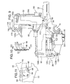
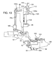
- the carriage 30 preferably includes an ink reservoir-mounting portion 50 pivotally secured to a printhead mounting-portion 52 at pivot point 56 defining an engaged position 58 of the ink reservoir-mounting portion 50 relative to the printhead mounting-portion 52 shown in FIG. 2, an open position 60 shown in FIG. 13, and an unlatched position 62 shown in FIG. 12.
- One known way to pivotally secure these mounting portions 50, 52 together includes extending a shaft 64 from the pivot point 56 on one of themounting portions 50, 52 into a mating hole received on the other of the mounting portions 50, 52.
- the mating hole preferably includes a notched tab 66 sized to receive a mating end portion 68 of the shaft 64 only when the ink reservoir-mounting portion 50 is at a defined position relative to the printhead mounting-portion 52.
- the mating end portion 68 serves to keep these two mounting portions 50, 52 together during operation of the assembled product.
- the printhead mounting-portion 52 includes a guide rod-engaging portion 70 for operably engaging the guide rod 40 and the printhead mounting-portion 52 for operably receiving at least one detachable printhead 32 therein.
- the carriage 30 shown in FIGS. 2, 9, 12, and 13 is sized to receive four printheads 32a-d (only printheads 32a, 32d are shown in the figures) so that it can print in a plurality of colors such as black, cyan, magenta and yellow.
- Each of the printheads 32a-d is in electrical communication with the printer controller to engage when commanded by the printer controller.
- the ink reservoir-mounting portion 50 is sized and shaped to operably receive at least one detachable ink reservoir 24a, 24b therein.
- the ink reservoir-mounting portion 50 preferably includes a forward flange 72, rearward flange 74, left flange 76, and right flange 78 defining an ink reservoir chamber 80 therein.
- the ink reservoir-mounting portion 50 includes at least one internal flange 82 defining a plurality of ink reservoir chambers 80a, 80b therein.
- the carriage 30 shown in FIGS. 2, 9, 12, and 13 is sized to receive at least two different detachable ink reservoirs 24a, 24b therein, a left ink reservoir 24a and a right ink reservoir 24b.
- One of the ink reservoirs ((here the right ink reservoir 24b) preferably includes a plurality of ink chambers therein, thereby allowing it to store up to three different colors of ink.
- the other ink reservoir (here the left ink reservoir 24a) preferably includes a larger volume of a single color of ink. Accordingly, it can be filled with the most frequently used color of ink, which is usually black.
- each ink reservoir 24a, 24b preferably includes a conductive electrical connector engaging portion (not shown) positioned to operably engage a corresponding electrical connector 90 when the ink reservoirs 24a, 24b are seated into their respective ink reservoir chambers 80a, 80b.
- fluid channels 92 extend from openings (not shown) in the ink reservoirs 24a, 24b through the ink reservoir-mounting portion 50 to their respective printheads 32a-d when the ink reservoir-mounting portion 50 is in the engaged position 58.
- the pivoting connection between the ink reservoir-mounting portion 50 and the printhead mounting-portion 52 permits easy access to the printheads 32a-d for maintenance, service, or replacement.
- the carriage 30 can be positioned along the guide rod 40 to permit easy access to the carriage 30 through an access door 94 in the chassis 26 of the printer 20.
- the service lifts the ink reservoir-mounting portion 50 causing it to pivot about pivot point 56 and move to the open position 60, thereby exposing the printhead mounting-portion 52 and providing access to the printheads 32a-d.
- the ink supply from the ink reservoirs 24a, 24b to the printheads 32a-d is stopped when the carriage 30 is not in the engaged position 58 (FIG. 2).
- One known way to accomplish this is to maintain a substantially air tight seal between the ink reservoirs 24a, 24b and their respective printheads 32a-d when the carriage is in its engaged position 58 (FIG. 2). Accordingly, ejecting ink from the printheads 32a-d creates a vacuum in the fluid channels 92 that draws new ink from the ink reservoirs 24a, 24b into the channels. The substantial vacuum is broken when the carriage is moved out of its engaged position. Accordingly, no fluid flows through the channels 92 when the carriage is out of its engaged position.
- a rod 98 is positioned adjacent to each channel 92 and operably extends from the ink reservoir-mounting portion 50 to the printhead mounting-portion 52.
- each rod 98 is biased to an extended position such that urging the ink reservoir-mounting portion 50 from its unlatched position 62 (FIG. 12) to its engaged position 58 (FIG. 2) causes each rod 98 to retract, thereby applying a force between the ink reservoir-mounting portion 50 and printhead mounting portion 52. This force facilitates maintaining the printheads 32a-d on the current datums.
- the fluid cannels 92 include interlocking nozzles 100 and mating recesses 102 on the ink reservoir-mounting portion 50 and the printhead mounting-portion 52 that interlock together when the ink reservoir-mounting portion 50 is in the engaged position 58 (FIG. 2), thereby allowing fluid to flow through the fluid channels 92 and making the connections substantially air tight.
- retractable seals 104 that are biased to an extended position operably engage each nozzle 100 and mating recess 102 connection when the ink reservoir-mounting portion 50 is in its engaged position 58, thereby preventing inadvertent leaking of air into the ink channels.
- Filters (not shown) are also preferably placed in the fluid path at these connections, thereby preventing inadvertent contamination the printheads 32a-d.
- a resistive detent 108 may be positioned in one of the ink reservoir-mounting portion 50 or the printhead mounting-portion 52.
- the resistive detent 108 operably engages a tab 110 extending from the other of the ink reservoir-mounting portion 50 or the printhead mounting-portion 52 when the ink reservoir-mounting portion50 is in its open position 60, thereby holding the ink reservoir-mounting portion 50 in place.
- a latching mechanism 112 is provided to secure the ink reservoir-mounting portion 50 in its engaged position 58 (FIG. 2). Moreover, because of the relatively large forces associated with deflecting the rods 98 of the ink flow valves out of their neutral positions, it is desirable that the latching mechanism 112 operate as a lever, thereby minimizing the amount of force required by a user to secure the lever.
- the latching mechanism 112 preferably includes a handle 114 pivotally secured to the ink reservoir-mounting portion 50 at a pivot 116 such that the handle114 defines a lever arm 118 on one side of the pivot 116 and a moment arm 120 on the other side of the pivot 116.
- a left and right joining arm 122a, 122b, respectively, are pivotally secured to the moment arm 120 at a point spaced apart for the pivot 116.
- the opposite ends 124 of the joining arms 122a, 122b include openings 126 for receiving hooks 128 extending from the printhead mounting-portion 52.
- the user positions the openings 126 on the joining arms 122a, 122b over the hooks 128 extending from the printhead mounting-portion 52.
- the user then moves the lever arm 118 of the handle 114 in the direction of arrow 130 (FIG. 12). This action urges the ink reservoir-mounting portion 50 to pivot about the pivot 116 toward the printhead mounting-portion 52, drawing these two portions together.
- the printer 20 includes one or more devices to facilitate and ensure that the detachable printer components, such as the ink reservoirs 24a, 24b, are properly installed, seated and aligned in their appropriate mounting portions 50, 52.
- the detachable printer components such as the ink reservoirs 24a, 24b
- Detachable printer components such as the ink reservoirs 24a, 24b of the present embodiment, can be installed into the ink reservoir-mounting portion 50 through a "toe-heel" installation mechanism and procedure.
- a "toe-heel" installation mechanism and procedure To facilitate understanding of this installation process in a printer 20, the following example is offered for the ink reservoirs 24a, 24b of the present invention. It should be appreciated by those skilled in the art that the principles of this procedure would work equally well with any other type of removable printer component, such as a traditional ink/printhead cartridge, printhead 32, or an off-axis mounted ink reservoir.
- the ink reservoirs 24a, 24b each have a defined shape, such as rectangle defining a leading, toe end 140 and a rearward-mounting end 142.
- the ink reservoirs 24a, 24b are slightly smaller than the shape of their corresponding ink reservoir chambers 80a, 80b.
- Left and right toe-end guides 146a, 146b extend from the left and right sides 148a, 148b of each ink reservoir 24a, 24b, and slidably engage guide rails 150 aligned along the respective left and right sides 148a, 148b of the corresponding ink reservoir chambers 80a, 80b, the guide rails 150 lead to toe-end guide receptacles 152 toward the rear end 154 of the ink reservoir chambers 80a, 80b for operably securing the toe-end guides 146a, 146b therein.
- Front tabs (not shown) extend from the ink reservoirs 24a, 24b to operably engage mating tab mounting chambers 155 received in the ink reservoir chambers 80a, 80b.
- the rearward-mounting end 142 of the ink reservoirs 24a, 24b preferably includes left and right rearward mounting end guides 158a, 158b sized to slidably engage respective mating slots 160a, 160b received on the respective side walls of the ink reservoir chambers 80a, 80b.
- a lever 162, operably secured toward the lower portion 164 of the rearward-mounting end 142 of the ink reservoirs 24a, 24b is biased to an extended position 166 (shown in FIG. 2).
- the lever162 includes a notch 168 extending therefrom for operably engaging a lip 170 (FIG. 5) on the forward flange 72 of the ink reservoir-mounting portion 50, thereby detachably securing the ink reservoirs 24a, 24b to the ink reservoir mounting-portion 50.
- Each ink reservoir 24a, 24b is installed into its respective ink reservoir chamber 80a, 80b by the installer first placing the toe end 140 into the respective ink reservoir chamber 80a, 80b such that the left and right toe-end guides 146a, 146b slidably engage guide rails 150. The user slides the toe end 140 of the ink reservoir 24a, 24b toward the toe-end guide receptacles152.
- the user presses down on the upper surface 172 of the ink reservoir 24a, 24b toward the rearward-mounting end 142, causing the left and right rearward mounting end guides 158a, 158b to slidably engage their respective mating slots 160a, 160b, and thereby properly positing the ink reservoirs 24a, 24b into their respective ink reservoir chambers 80a, 80b.
- a mounting portion cover 180 that extends above and partially over the ink reservoir chambers 80a, 80b can be operably mounted to the ink reservoir-mounting portion 50.
- the cover 180 includes a substantially planar top surface 182 positioned over the ink reservoir chambers 80a, 80b receiving the toe end 140 of the ink reservoirs 24a, 24b.
- the planar top surface 182 is positioned above each ink reservoir 24a, 24b when each ink reservoir 24a, 24b is fully installed on the ink reservoir-mounting portion 50, and it extends over the ink reservoirs 24a, 24b only by an amount that precludes it from interfering with the toe-heel installation previously described. Accordingly, as best shown in FIG. 5, so long as the installer performs a toe-heel installation of the detachable printer component, the mounting portion cover 180 does not interfere with the installation.
- the cover 180 blocks the toe end 140 of the ink reservoir 24a, 24b from entering the respective ink reservoir chambers 80a, 80b, thereby alerting the installer of the improper installation.
- the mounting portion cover 180 blocks the toe end 140 of the ink reservoir 24a, 24b from entering the respective ink chamber 80a, 80b, thereby alerting the installer of the improper installation method.
- the mounting portion cover180 blocks the toe end 140 of the ink reservoir 24a, 24b from entering into the respective ink reservoir chambers 80a, 80b.
- the cover 180 is pivotally secured to the ink reservoir-mounting portion 50 at pivot point 194 by arms 196 that extend from the substantially planar top surface 182 and at least one beam spring 198 extends from the substantially planar top surface 182 to operably engage the rearward flange 74 of the ink reservoir-mounting portion 50, thereby biasing the cover 180 to a neutral position shown in FIG. 2.
- the beam spring 198 and pivot point 194 allow the substantially planar top surface 182 to deflect slightly upward during the toe-heel installation process, but also urge the deflected substantially planar top surface 182 and the toe end 140 of the ink reservoir 24a, 24b in contact with it, toward the respective ink reservoir chamber 80a, 80b, thereby further facilitating installation of the ink reservoir.
- the leading edge 200 of the substantially planar top surface 182 may be angled upward as best shown in FIG. 5, to further facilitate entry of the toe end 140 of the ink reservoir 24a, 24b below the cover 180.
- the cover 180 is preferably a contrasting color from the ink reservoir-mounting portion 50 and printhead mounting-portion 52 of the carriage 30.
- the contrast in color between these components makes the cover 180 appear more readily to an installer, thereby alerting the installer of this obstacle to improper installation of the ink reservoirs.
- a spring 210 is preferably operably secured within the ink reservoir chambers 80a, 80b to facilitate installation and remove of the ink reservoirs 24a, 24b.
- the spring 210 biases each ink reservoir 24a, 24b to an uninstalled position 212 shown in solid lines in FIG. 5, but remains compressed while each respective ink reservoir 24a, 24b is latched in its installed position 214 shown in dashed lines in FIG. 5.
- the spring 210 includes a generally c-shaped mounting portion 216 and an elongate beam portion 218 extending therefrom.
- the distal end 220 of the beam portion 218 can include an angled end 222 aligned to support each ink reservoir 24a, 24b in its uninstalled position 212.
- the c-shaped mounting portion 216 is preferably clipped to an arm 224 extending from the ink reservoir-mounting portion 50 below each respective ink reservoir chamber 80a, 80b.
- each ink reservoir chamber 80a, 80b includes a recess 226 for receiving the spring 210 when each respective ink reservoir 24a, 24b is in its installed position 214 within the respective ink reservoir chamber 80a, 80b.
- Known preferable materials for constructing the spring 210 include high yield stainless steel and beryllium copper.
- the specific shape of the spring may be changed to optimize its force and displacement characteristics.
- a particularly effective beam shape is a triangle having a wide base toward the c-shaped mounting portion 216 that narrows at it approaches the distal end 220 of the spring.
- a similarly shaped portion of material may be removed from the beam portion as shown in FIG. 6, thereby further enhancing the force characteristics provided by the spring 210.
- the spring 210 facilitates installation of each ink reservoir 24a, 24b by encouraging a toe-heel installation of each ink reservoir 24a, 24b.
- the toe end 140 of that ink reservoir 24a is properly aligned such that the left and right toe-end guides 146a, 146b are operably received within their respective toe-end guide receptacles 152.
- the spring 210 facilitates easy removal of an ink reservoir 24a by urging the rearward-mounting end 142 of the ink reservoir 24a up when the lever162 is unlatched.
- the printer chassis 26 includes defined stops (not shown) that operably engage the rearward-mounting end 142 when the ink reservoir 24a is in its uninstalled position 212 shown in FIG. 5. The location of the carriage 30 when the rearward-mounting end 142 contacts these stops can then be used to signal the user of the improper ink reservoir 24a installation via a computer interface, warning light, or the like.
- the printer includes one or more separable key elements 22a, 22b as best shown in FIGS. 2, 3, 7 and 8.
- each detachable printer component such as the ink reservoirs 24a, 24b shown in FIG. 2, includes a unique pattern of identifying tabs 220a-f extending therefrom.
- the left ink reservoir 24a includes tabs 220a-c, two of which areto the left of the left ink reservoir's lever 162
- the right ink reservoir 24b includes tabs 220d-f, two of which are to the right of the right ink reservoir's lever162.
- This pattern of tabs 220a-f can be used to indicate the type, color, and/or quality of ink contained that particular printer.
- the tab pattern for the left ink reservoir 24a can indicate that it contains black ink
- the tab pattern displayed on the right ink reservoir 24b can indicate that the right ink reservoir is a multi-chamber reservoir containing blue, magenta, and yellow colored ink.
- the correct location and orientation of the removable printer components are defined.
- an ink reservoir containing black ink must be installed in an ink cartridge chamber that is in fluid communication with a black ink channel and related printhead. If a different color of ink were inadvertently placed in the channel and the corresponding printhead, these components would become contaminated and no longer function as designed. Accordingly, it is important that the correct ink supply be mounted in the correct ink chamber.
- Each key element 22a, 22b includes a unique pattern of slots 224a-f to receive one of the available unique pattern of identifying tabs 220a-f therethrough, and preclude a different pattern of identifying tabs 220a-f from passing therethrough.
- the key element 22 is operably secured to the ink reservoir-mounting portion 50 adjacent to the space occupied by the tabs 220a-c on one of the ink reservoirs 24a when that ink reservoir 24a is in its installed position on the ink reservoir-mounting portion 50.
- each key element 22a, 22b includes a base-mounting portion 230 having a key tab portion 232, an identifying label tab portion 234, and a mounting portion 236 extending therefrom.
- the mounting portion 236 includes a mounting slot 238 sized to be received on the forward flange 72 of the ink reservoir-mounting portion 50 and a hook 240 for operably engaging the forward flange 72.
- the forward flange 72 and mounting portion 236 include a unique set of mating slots 245, thereby preventing an incorrect key element 22 from being installed at that particular location on the forward flange 72.
- the label tab portion 234 includes a display surface 244 for receiving a label 246, preferably having unique surface indicia 248 thereon indicating the type of detachable printer component that the key element will accept.
- a label 246, preferably having unique surface indicia 248 thereon indicating the type of detachable printer component that the key element will accept.
- one label 246a can indicate the key element 22a to which it is attached receives a black ink reservoir.
- a separate key label 246b installed on a separate key element 22b can indicate that the key element 22b to which it is attached receives a multi-color ink reservoir.
- each display surface includes a unique shape or orientation.
- the display surface 244 on one key element 22b can have a flat bar 252 on the left side of the display surface and a rounded right side, while the display surface 244 on another key element 22a may place the flat bar 252 on the right side and have a rounded left side. Accordingly, the likelihood that an assembler may place the wrong label 246a, 246b, on the display surface 244 is reduced, because the correct label for each display surface 244 can have the same shape corresponding to the display surface to which it is correctly attached.
- the foregoing key elements 22a, 22b may be detachably secured to the printer 20. Accordingly, a family of printers can rely on the same basic carriage 30 and the like to build a variety of different printers having different functionality. Configuration control for a given printer installation is regulated by the manufacture selecting the appropriate key elements 22a, 22b for that particular printer configuration.
- the key elements 22a, 22b need only be changed in order to re-key the ink reservoir chambers to accept the new ink reservoirs.
Landscapes
- Ink Jet (AREA)
Applications Claiming Priority (2)
| Application Number | Priority Date | Filing Date | Title |
|---|---|---|---|
| US919733 | 1986-10-16 | ||
| US09/919,733 US6779874B2 (en) | 2001-07-31 | 2001-07-31 | Device for ensuring proper toe-heel installation of a detachable printer component |
Publications (2)
| Publication Number | Publication Date |
|---|---|
| EP1281531A1 true EP1281531A1 (de) | 2003-02-05 |
| EP1281531B1 EP1281531B1 (de) | 2008-09-17 |
Family
ID=25442557
Family Applications (1)
| Application Number | Title | Priority Date | Filing Date |
|---|---|---|---|
| EP02255027A Expired - Lifetime EP1281531B1 (de) | 2001-07-31 | 2002-07-17 | Vorrichtung zur Sicherstellung einer fehlerfreien Installation einer abnehmbaren Druckerkomponente |
Country Status (6)
| Country | Link |
|---|---|
| US (1) | US6779874B2 (de) |
| EP (1) | EP1281531B1 (de) |
| JP (1) | JP3732808B2 (de) |
| KR (1) | KR20030011700A (de) |
| DE (1) | DE60228915D1 (de) |
| TW (1) | TW583101B (de) |
Families Citing this family (7)
| Publication number | Priority date | Publication date | Assignee | Title |
|---|---|---|---|---|
| US6994423B2 (en) * | 2004-03-18 | 2006-02-07 | Nu-Kote International, Inc. | Printer carriage interlock for ink cassette |
| JP4590317B2 (ja) * | 2005-07-04 | 2010-12-01 | キヤノン株式会社 | 記録装置 |
| US7789500B2 (en) * | 2006-12-21 | 2010-09-07 | Eastman Kodak Company | Printing device fluid reservoir chassis with alignment features |
| JP4981105B2 (ja) * | 2009-07-09 | 2012-07-18 | シルバーブルック リサーチ ピーティワイ リミテッド | ページ幅印字ヘッドプリンタカートリッジの共通インクジェットプリンタクレードル |
| JP4932936B2 (ja) * | 2009-11-17 | 2012-05-16 | キヤノンファインテック株式会社 | 画像形成装置 |
| JP6171313B2 (ja) * | 2011-12-08 | 2017-08-02 | セイコーエプソン株式会社 | 液体噴射装置 |
| JP7275732B2 (ja) * | 2019-03-25 | 2023-05-18 | セイコーエプソン株式会社 | 印刷装置 |
Citations (4)
| Publication number | Priority date | Publication date | Assignee | Title |
|---|---|---|---|---|
| EP0756937A2 (de) * | 1995-08-01 | 1997-02-05 | Brother Kogyo Kabushiki Kaisha | Verbindungsstruktur für Druckkopfbefestigung und Farbstoffpatronen |
| EP0818314A2 (de) * | 1996-07-12 | 1998-01-14 | Canon Kabushiki Kaisha | Flüssigkeitsbehälter, Kopfpatrone, Flüssigkeitsausstossgerät und Steuerverfahren |
| US6050667A (en) * | 1997-03-11 | 2000-04-18 | Brother Kogyo Kabushiki Kaisha | Ink cartridge holding device having cap-covered switch |
| EP1053875A1 (de) * | 1999-04-27 | 2000-11-22 | Canon Kabushiki Kaisha | Tintenbehälter, Halter für den Tintenbehälter, Tintenstrahlaufzeichnungsgerät den Halter beinhaltend und Methode zum Einsetzen des Tintenbehälters in den Halter |
Family Cites Families (18)
| Publication number | Priority date | Publication date | Assignee | Title |
|---|---|---|---|---|
| US4907018A (en) * | 1988-11-21 | 1990-03-06 | Hewlett-Packard Company | Printhead-carriage alignment and electrical interconnect lock-in mechanism |
| US5563638A (en) | 1992-09-21 | 1996-10-08 | Hewlett-Packard Company | Ink-jet printhead capping and wiping method and apparatus |
| US5621441A (en) | 1992-09-21 | 1997-04-15 | Hewlett-Packard Company | Service station for inkjet printer having reduced noise, increased ease of assembly and variable wiping capability |
| US5646665A (en) * | 1993-04-30 | 1997-07-08 | Hewlett-Packard Company | Side biased datum scheme for inkjet cartridge and carriage |
| US5408746A (en) * | 1993-04-30 | 1995-04-25 | Hewlett-Packard Company | Datum formation for improved alignment of multiple nozzle members in a printer |
| JP3133906B2 (ja) * | 1993-08-19 | 2001-02-13 | キヤノン株式会社 | インクタンクカートリッジ |
| US5684518A (en) | 1993-10-29 | 1997-11-04 | Hewlett-Packard Company | Interconnect scheme for mounting differently configured printheads on the same carriage |
| US5619239A (en) * | 1993-11-29 | 1997-04-08 | Canon Kabushiki Kaisha | Replaceable ink tank |
| US5712668A (en) | 1994-03-25 | 1998-01-27 | Hewlett-Packard Company | Rotary Multi-ridge capping system for inkjet printheads |
| JP3042826B2 (ja) * | 1995-02-21 | 2000-05-22 | キヤノン株式会社 | インクタンク、および該インクタンクを着脱自在に保持するホルダを備えたインクジェット記録装置 |
| US6183077B1 (en) | 1995-04-27 | 2001-02-06 | Hewlett-Packard Company | Method and apparatus for keying ink supply containers |
| JP3280202B2 (ja) * | 1995-08-01 | 2002-04-30 | ブラザー工業株式会社 | インクジェットプリンタ |
| US6139135A (en) | 1997-03-03 | 2000-10-31 | Hewlett-Packard Company | Inkjet printing with replaceable set of ink-related components (printhead/service module/ink supply) for each color of ink |
| US5949459A (en) | 1997-06-04 | 1999-09-07 | Hewlett-Packard Company | Method and apparatus for securing an ink container |
| US6135585A (en) | 1999-01-08 | 2000-10-24 | Hewlett-Packard Company | Replaceable capping system for inkjet printheads |
| JP2001063097A (ja) * | 1999-04-27 | 2001-03-13 | Canon Inc | 液体供給システム及び該システムに用いられる液体供給容器 |
| US6443567B1 (en) * | 1999-04-27 | 2002-09-03 | Canon Kabushiki Kaisha | Liquid ejecting cartridge and recording device using same |
| JP2001058417A (ja) * | 1999-08-24 | 2001-03-06 | Canon Inc | インクタンク、記録ヘッドカートリッジおよびインクジェット記録装置 |
-
2001
- 2001-07-31 US US09/919,733 patent/US6779874B2/en not_active Expired - Lifetime
-
2002
- 2002-05-13 TW TW091109923A patent/TW583101B/zh not_active IP Right Cessation
- 2002-07-12 JP JP2002203966A patent/JP3732808B2/ja not_active Expired - Fee Related
- 2002-07-17 EP EP02255027A patent/EP1281531B1/de not_active Expired - Lifetime
- 2002-07-17 DE DE60228915T patent/DE60228915D1/de not_active Expired - Lifetime
- 2002-07-30 KR KR1020020045001A patent/KR20030011700A/ko not_active Withdrawn
Patent Citations (4)
| Publication number | Priority date | Publication date | Assignee | Title |
|---|---|---|---|---|
| EP0756937A2 (de) * | 1995-08-01 | 1997-02-05 | Brother Kogyo Kabushiki Kaisha | Verbindungsstruktur für Druckkopfbefestigung und Farbstoffpatronen |
| EP0818314A2 (de) * | 1996-07-12 | 1998-01-14 | Canon Kabushiki Kaisha | Flüssigkeitsbehälter, Kopfpatrone, Flüssigkeitsausstossgerät und Steuerverfahren |
| US6050667A (en) * | 1997-03-11 | 2000-04-18 | Brother Kogyo Kabushiki Kaisha | Ink cartridge holding device having cap-covered switch |
| EP1053875A1 (de) * | 1999-04-27 | 2000-11-22 | Canon Kabushiki Kaisha | Tintenbehälter, Halter für den Tintenbehälter, Tintenstrahlaufzeichnungsgerät den Halter beinhaltend und Methode zum Einsetzen des Tintenbehälters in den Halter |
Also Published As
| Publication number | Publication date |
|---|---|
| EP1281531B1 (de) | 2008-09-17 |
| JP3732808B2 (ja) | 2006-01-11 |
| KR20030011700A (ko) | 2003-02-11 |
| US6779874B2 (en) | 2004-08-24 |
| JP2003053965A (ja) | 2003-02-26 |
| TW583101B (en) | 2004-04-11 |
| DE60228915D1 (de) | 2008-10-30 |
| US20030025764A1 (en) | 2003-02-06 |
Similar Documents
| Publication | Publication Date | Title |
|---|---|---|
| US6729714B2 (en) | Separable key for establishing detachable printer component compatibility with a printer | |
| EP1281530B1 (de) | Auf der Achse drehbarer Tintenbehälter für Tintenstrahldrucker | |
| US6305795B2 (en) | Ink container having electronic and mechanical features enabling plug compatibility between multiple supply sizes | |
| US6386692B1 (en) | Ink container configured for use with compact supply station | |
| EP2310207B1 (de) | Behälterinstallationsführung für eine fluidejektoranordnung | |
| US6179401B1 (en) | Multi-component installation feedback system for replacement print cartridges, valve holders, and service station cassettes for on board ink delivery systems replenishment | |
| CN1252758A (zh) | 固定墨盒的方法和设备 | |
| BRPI0718248A2 (pt) | Recipiente de líquido, suporte de recipiente e aparelho de consumo de líquido | |
| JP4382170B2 (ja) | インクジェットプリンタにおけるインク供給ステーション、該ステーションに使用されるインク供給容器並びに補充インク供給品の供給方法 | |
| EP1281531B1 (de) | Vorrichtung zur Sicherstellung einer fehlerfreien Installation einer abnehmbaren Druckerkomponente | |
| US6113229A (en) | Interchangeable fluid interconnect attachment and interface | |
| US20020057317A1 (en) | Ink container configured for use with printer | |
| EP2195171A1 (de) | Patronennhalter | |
| US7871159B2 (en) | Ink loader with adjustable insertion openings |
Legal Events
| Date | Code | Title | Description |
|---|---|---|---|
| PUAI | Public reference made under article 153(3) epc to a published international application that has entered the european phase |
Free format text: ORIGINAL CODE: 0009012 |
|
| AK | Designated contracting states |
Designated state(s): AT BE BG CH CY CZ DE DK EE ES FI FR GB GR IE IT LI LU MC NL PT SE SK TR |
|
| AX | Request for extension of the european patent |
Extension state: AL LT LV MK RO SI |
|
| 17P | Request for examination filed |
Effective date: 20030318 |
|
| AKX | Designation fees paid |
Designated state(s): DE FR GB IT |
|
| 17Q | First examination report despatched |
Effective date: 20050718 |
|
| GRAP | Despatch of communication of intention to grant a patent |
Free format text: ORIGINAL CODE: EPIDOSNIGR1 |
|
| GRAS | Grant fee paid |
Free format text: ORIGINAL CODE: EPIDOSNIGR3 |
|
| GRAA | (expected) grant |
Free format text: ORIGINAL CODE: 0009210 |
|
| AK | Designated contracting states |
Kind code of ref document: B1 Designated state(s): DE FR GB IT |
|
| REG | Reference to a national code |
Ref country code: GB Ref legal event code: FG4D |
|
| REF | Corresponds to: |
Ref document number: 60228915 Country of ref document: DE Date of ref document: 20081030 Kind code of ref document: P |
|
| PLBE | No opposition filed within time limit |
Free format text: ORIGINAL CODE: 0009261 |
|
| STAA | Information on the status of an ep patent application or granted ep patent |
Free format text: STATUS: NO OPPOSITION FILED WITHIN TIME LIMIT |
|
| 26N | No opposition filed |
Effective date: 20090618 |
|
| PG25 | Lapsed in a contracting state [announced via postgrant information from national office to epo] |
Ref country code: IT Free format text: LAPSE BECAUSE OF FAILURE TO SUBMIT A TRANSLATION OF THE DESCRIPTION OR TO PAY THE FEE WITHIN THE PRESCRIBED TIME-LIMIT Effective date: 20080917 |
|
| REG | Reference to a national code |
Ref country code: FR Ref legal event code: ST Effective date: 20100331 |
|
| PG25 | Lapsed in a contracting state [announced via postgrant information from national office to epo] |
Ref country code: FR Free format text: LAPSE BECAUSE OF NON-PAYMENT OF DUE FEES Effective date: 20090731 |
|
| REG | Reference to a national code |
Ref country code: GB Ref legal event code: 732E Free format text: REGISTERED BETWEEN 20120329 AND 20120404 |
|
| PGFP | Annual fee paid to national office [announced via postgrant information from national office to epo] |
Ref country code: ES Payment date: 20180723 Year of fee payment: 16 |
|
| PGFP | Annual fee paid to national office [announced via postgrant information from national office to epo] |
Ref country code: DE Payment date: 20181207 Year of fee payment: 18 |
|
| GBPC | Gb: european patent ceased through non-payment of renewal fee |
Effective date: 20190717 |
|
| PG25 | Lapsed in a contracting state [announced via postgrant information from national office to epo] |
Ref country code: GB Free format text: LAPSE BECAUSE OF NON-PAYMENT OF DUE FEES Effective date: 20190717 |
|
| REG | Reference to a national code |
Ref country code: DE Ref legal event code: R119 Ref document number: 60228915 Country of ref document: DE |
|
| PG25 | Lapsed in a contracting state [announced via postgrant information from national office to epo] |
Ref country code: DE Free format text: LAPSE BECAUSE OF NON-PAYMENT OF DUE FEES Effective date: 20210202 |