EP1281646B1 - Maschine zum Vereinzeln von einer gewünschten Metallplattenanzahl aus einem Master-Stapel - Google Patents
Maschine zum Vereinzeln von einer gewünschten Metallplattenanzahl aus einem Master-Stapel Download PDFInfo
- Publication number
- EP1281646B1 EP1281646B1 EP02017133A EP02017133A EP1281646B1 EP 1281646 B1 EP1281646 B1 EP 1281646B1 EP 02017133 A EP02017133 A EP 02017133A EP 02017133 A EP02017133 A EP 02017133A EP 1281646 B1 EP1281646 B1 EP 1281646B1
- Authority
- EP
- European Patent Office
- Prior art keywords
- cradle
- bed
- pack
- metal sheets
- machine
- Prior art date
- Legal status (The legal status is an assumption and is not a legal conclusion. Google has not performed a legal analysis and makes no representation as to the accuracy of the status listed.)
- Expired - Lifetime
Links
- 239000002184 metal Substances 0.000 title claims abstract description 37
- 230000000284 resting effect Effects 0.000 claims description 4
- 238000000926 separation method Methods 0.000 description 6
- 239000000463 material Substances 0.000 description 4
- 229910000831 Steel Inorganic materials 0.000 description 3
- 239000004033 plastic Substances 0.000 description 3
- 239000010959 steel Substances 0.000 description 3
- 239000000956 alloy Substances 0.000 description 2
- 229910045601 alloy Inorganic materials 0.000 description 2
- 241000252254 Catostomidae Species 0.000 description 1
- 230000000712 assembly Effects 0.000 description 1
- 238000000429 assembly Methods 0.000 description 1
- 230000000694 effects Effects 0.000 description 1
- 239000000284 extract Substances 0.000 description 1
- 239000003302 ferromagnetic material Substances 0.000 description 1
- 230000005484 gravity Effects 0.000 description 1
- 238000003780 insertion Methods 0.000 description 1
- 230000037431 insertion Effects 0.000 description 1
- 238000000034 method Methods 0.000 description 1
- 239000002985 plastic film Substances 0.000 description 1
Images


Classifications
-
- B—PERFORMING OPERATIONS; TRANSPORTING
- B65—CONVEYING; PACKING; STORING; HANDLING THIN OR FILAMENTARY MATERIAL
- B65H—HANDLING THIN OR FILAMENTARY MATERIAL, e.g. SHEETS, WEBS, CABLES
- B65H3/00—Separating articles from piles
- B65H3/32—Separating articles from piles by elements, e.g. fingers, plates, rollers, inserted or traversed between articles to be separated and remainder of the pile
- B65H3/322—Separating articles from piles by elements, e.g. fingers, plates, rollers, inserted or traversed between articles to be separated and remainder of the pile for separating a part of the pile, i.e. several articles at once
-
- B—PERFORMING OPERATIONS; TRANSPORTING
- B65—CONVEYING; PACKING; STORING; HANDLING THIN OR FILAMENTARY MATERIAL
- B65H—HANDLING THIN OR FILAMENTARY MATERIAL, e.g. SHEETS, WEBS, CABLES
- B65H2301/00—Handling processes for sheets or webs
- B65H2301/30—Orientation, displacement, position of the handled material
- B65H2301/33—Modifying, selecting, changing orientation
- B65H2301/332—Turning, overturning
- B65H2301/3321—Turning, overturning kinetic therefor
- B65H2301/33212—Turning, overturning kinetic therefor about an axis parallel to the direction of displacement of material
-
- B—PERFORMING OPERATIONS; TRANSPORTING
- B65—CONVEYING; PACKING; STORING; HANDLING THIN OR FILAMENTARY MATERIAL
- B65H—HANDLING THIN OR FILAMENTARY MATERIAL, e.g. SHEETS, WEBS, CABLES
- B65H2301/00—Handling processes for sheets or webs
- B65H2301/30—Orientation, displacement, position of the handled material
- B65H2301/33—Modifying, selecting, changing orientation
- B65H2301/332—Turning, overturning
- B65H2301/3322—Turning, overturning according to a determined angle
- B65H2301/33222—90°
Definitions
- the present invention relates to a machine which enables a desired number of metal sheets to be separated from a so-called master pack, in order to form a so-called derivative pack or an assembly of several derivative packs.
- master pack means a pack of sheets of any metal or alloy, usually separated from each other by a paper sheet, the pack being rested on a relative pallet which facilitates its handling.
- derivative pack means a pack which is formed from the metal sheets withdrawn from the master pack and still separated from each other by a paper sheet, and is for example to be despatched to a client. In the assembly formed from several derivative packs, a sheet of plastic material is normally interposed to divide the various derivative packs from each other.
- the object of the present invention is to provide a machine which enables the desired number of metal sheets to be withdrawn from a master pack, and form a derivative pack or an assembly of derivative packs with total safety and minimum fatigue for the personnel concerned.
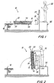
- the machine of the invention comprises a first cradle 12 which itself comprises a bed 14 movable parallel to itself, and a perpendicular side wall 16.
- the first cradle 12 is conveniently constructed with a structure formed from steel sections. Neither the bed 14 nor the side wall 16 needs to have a continuous surface, they being able to be in the form for example of a rack or a frame also constructed from steel sections.
- the bed 14 is moved parallel to itself for example by conventional hydraulically operated devices.
- FIG. 1 the machine 10 is shown in its stand-by position in which, by means for example of an automatic conveyor 18 (partly shown in said figure), a master pack of metal sheets 20, provided with its relative pallet 22, is disposed on the bed 14 of the machine 10.
- a master pack of metal sheets 20, provided with its relative pallet 22 is disposed on the bed 14 of the machine 10.
- a motorized roller table which extends along the centre of the rack forming the bed 14 when the first cradle 12 lies in its aforesaid first position (i.e. in the horizontal position), with the right side of the master pack 20 resting against the side wall 16 of the first cradle 12.
- the master pack can be fed to the machine 10 in other ways, for example by a conventional fork lift truck.
- the machine 10 comprises a second cradle 24 also comprising a bed 26 and relative perpendicular side wall 28.
- the second cradle with its relative bed 26 and side wall 28 can be formed in a similar manner to that already described with regard to the first cradle 12, so that no further description will be given.
- the second cradle 24 lies in the position already described as its second position, in which it has an orientation close to the vertical.
- the machine 10 is also provided with a station 32 for the operator or operators (normally not more than two). In the figure a single operator is shown for simplicity, indicated by 30.
- This station consists essentially of a raised footboard or gangway on which all the various controls of the machine 10 (not shown for simplicity) are disposed in a manner easily accessible by the operator. These controls are connected to a control unit of microprocessor type, and in particular to a personal computer (not shown in the figures for simplicity).
- the operator 30 When a master pack 20 has been disposed on the bed 14, the operator 30 operates a relative control to cause the control unit to activate corresponding operating means (not shown, but of conventional type, and preferably of hydraulic type) which move the first cradle 12 from its first position ( Figure 1) to its second position ( Figure 2) in which the master pack 20 has an orientation as close as possible to vertical (in this, taking obvious account of the fact that the metal sheets of the pack 20 must always lie in a safety condition, i.e. without any tendency to accidentally overturn against the bed 26 of the adjacent second cradle 24, which could represent a danger to the operator 30, especially to his hands).
- corresponding operating means not shown, but of conventional type, and preferably of hydraulic type
- the control unit then activates other operating means (indicated schematically by the arrows 34 in Figure 2) to move the bed 26 from its withdrawn position ( Figure 1) to its advanced position ( Figure 2) in which the lower edge of the bed 14 touches the master pack 20.
- the operator 30 can now count the number of metal sheets to be separated, making them overturn one or more at a time (according to what is most comfortable) with hits hands (this being very simple, in view of the position of the master pack 20), so that the desired number of metal sheets to be separated lie in the condition shown in Figure 3, in which these metal sheets form a derivative pack 36 which rests against the bed 26 of the second cradle 24.
- the derivative pack 36 however still lies with its edge against the side wall 16 of the first cradle 12.
- the remaining metal sheets of the master pack are indicated in Figure 3 by 20A. At this point the operator 30 extracts any paper separation sheet lying between the derivative pack 26 and the remainder of the master pack 20A.
- the control unit causes a separation element 38 in the form of a wedge (not visible in Figures 1 and 2 because it lies at a height outside the range of said figures) to descend from above ( Figure 3).
- This wedge 38 can be conveniently suspended on steel cables (not shown), so that it can be easily raised and lowered by a conventional hoist.
- the wedge 38 is conveniently covered with a suitable material to prevent damage to the metal sheets with which it comes into contact.
- the wedge 38 must be lowered in such a manner that it becomes inserted between the remainder 20A of the master pack and the derivative pack 36 which has just been formed, the wedge 38, if of sufficient weight, attaining the position indicated by 38A in Figure 3 by gravity.
- the control unit causes the wedge 38, which extends at its two sides beyond the metal sheets, to be engaged by pusher means (not shown for simplicity, but of conventional type), conveniently of hydraulic operation, which exert on the wedge 38 a horizontal thrust in the direction of the second cradle 24.
- the control unit inactivates the operating means 34, so that the relative bed 26, under the thrust of the wedge 38, withdraws together with the derivative pack 36, until appropriate sensors (not shown) with which the machine 10 is provided (for example photosensors) sense that the entire derivative pack 36 has been transferred beyond the horizontal line 40 forming the boundary line between the side wall 16 of the first cradle 12 and the side wall 28 of the second cradle 24.
- the control unit causes the separation wedge 38 to rise, so that it is no longer visible in Figure 5.
- This figure shows the next stage, in which the first cradle 12 has been made to return by the control unit into its first position (horizontal). It is therefore possible to remove the remainder 20A of the master pack and hence be able, if required, to place on the bed 14 another master pack composed of metal sheets of dimensions or material different from the preceding.
- the new master pack is that indicated in Figure 5 by 20A, and in particular an incomplete master pack from which a determined number of metal sheets have already been removed (there is obviously no difference if the new master pack is complete), so that its upper face is moved to the level of the upper edge of the side wall 16.
- the control unit returns the first cradle 12 from its first position ( Figure 5) to its second position ( Figure 6).
- the operator 30 will have preferably placed on the free face of the derivative pack 36, already present on the second cradle 24, a sheet (normally of plastic material) which conveniently serves to divide the first derivative pack 36 from the new derivative pack which is to be formed and will be composed of a different type of metal sheet.
- the insertion operation for the separation wedge 38 is repeated as far as the position indicated by 38A in Figure 6, as is the operation involving the forced movement of the wedge towards the first derivative pack, with simultaneous withdrawal of the bed 14 from the second cradle 24 ( Figure 7), so as to accumulate on this latter the assembly of two derivative packs, this assembly being indicated in Figure 6 by 36A, whereas the remainder of the second master pack is indicated by 20B.
- Figure 8 describes the next stage, in which the first cradle 12, with the remainder 20B of the second master pack, is returned to its initial position.
- a conventional pallet or in the limit simple flat planking is disposed on the bed 14 of the first cradle 12.
- the control unit activates operating means (indicated schematically in Figure 9 by the arrows 44, preferably of hydraulic type) which enable the upper edge of the pallet 42 to be moved to the level of the upper edge of the side wall 16, the first cradle 12 then being brought into that position defined hereinbefore as its third position (vertical).
- the second cradle 24 is also brought into that position defined hereinbefore as its first position (also vertical), by which the situation of Figure 10 is obtained.
- the control unit activates the operating means 34 of the bed 26 so that the assembly of derivative packs 36A, including the pallet 42, is moved from the second cradle 24 to the first cradle 12, as shown in Figure 11.
- the control unit again by the intervention of the operator 30 or automatically (if sensors are provided to inform the control unit when this situation has been attained), the control unit returns the first cradle 12 to its first position, so that the assembly 36A of derivative packs can be removed, to hence conclude the scheduled cycle.
- the machine 10 is now ready to effect a new cycle.
- the machine 10 can conveniently be provided with conventional load cells which enable the weight of the formed derivative packs to be determined, either by difference or by addition.
- the machine of the present invention can be conveniently used in all those concerns which process sheets of any metal or alloy, or in which a client has to be supplied with assemblies formed from a determined number of metal sheets per type. It is immediately apparent that the machine of the present invention enables a considerable time and cost saving to be obtained, in addition to substantially eliminating the risk of accidents to the personnel concerned.
Landscapes
- Engineering & Computer Science (AREA)
- Mechanical Engineering (AREA)
- Sheets, Magazines, And Separation Thereof (AREA)
- Pile Receivers (AREA)
- Bending Of Plates, Rods, And Pipes (AREA)
Claims (5)
- Maschine zum Abtrennen einer gewünschten Anzahl von Metalltafeln von einem Hauptstapel, um einen abgeleiteten Stapel oder eine Gruppe von abgeleiteten Stapeln zu bilden, umfassend:ein zwischen einer horizontalen ersten Position, einer zweiten Position nahe der Vertikalen und einer vertikalen dritten Position bewegbares erstes Gestell (12), wobei das erste Gestell (12) mit einer Ladefläche (14) und einer relativ dazu senkrechten Seitenwand (16) ausgerüstet ist, wobei die Ladefläche in der Lage ist, einen Hauptstapel (20) mit der jeweiligen Palette aufzunehmen, wenn das erste Gestell (12) in seiner ersten Position ist, wobei in der zweiten Position des ersten Gestells (12) die Metalltafeln des Hauptstapels (20) mit ihren Kanten gegen die Seitenwand (16) des ersten Gestells (12) gelehnt ruhen, wobei das erste Gestell (12) zudem mit Mitteln (44) zum Bewegen seiner Ladefläche (14) parallel zu sich selbst ausgestattet ist,ein zwischen einer vertikalen ersten Position, in welcher es dem ersten Gestell (12), wenn dieses in seiner dritten Position ist, gegenüberliegt, und einer zweiten Position nahe der Vertikalen bewegbares zweites Gestell (24), wobei das zweite Gestell (24) mit einer Ladefläche (26) und einer relativ dazu senkrechten Seitenwand (28) ausgerüstet ist, wobei das zweite Gestell (24) zudem mit Mitteln (34) zum Bewegen seiner Ladefläche (26) parallel zu sich selbst ausgerüstet ist, wobei die freie Kante der Seitenwand (28) des zweiten Gestells (24) sowohl wenn beide Gestelle (12, 24) in ihren zweiten Positionen als auch wenn das erste Gestell (12) in seiner dritten Position und das zweite Gestell (24) in seiner ersten Position ist im Wesentlichen mit der freien Kante der Seitenwand (16) des ersten Gestells (12) übereinstimmt,ein Trennelement (38), welches zwischen die von dem ersten Gestell (12) getragenen Metalltafeln (20) einsetzbar ist, wenn das erste Gestell (12) in seiner zweiten Position ist, um die gewünschte Anzahl (36) von diesen von dem Hauptstapel (20) zu trennen, wobei das Trennelement (38) zudem als Schiebeelement gegen die abgetrennten Metalltafeln (36) arbeitet, um sie auf das zweite Gestell (24) zu bewegen, wenn dieses in seiner zweiten Position ist.
- Maschine (10) wie in Anspruch 1 beansprucht, wobei eine Operationssteuereinheit für die Maschine (10) bereitgestellt ist.
- Maschine (10) wie in Anspruch 2 beansprucht, wobei die Steuereinheit vom Typ eines Mikroprozessors ist.
- Maschine (10) wie in Anspruch 1 beansprucht, wobei Hydraulikmittel bereitgestellt sind, um das erste Gestell (12) und das zweite Gestell (24) in ihre verschiedenen Positionen zu bewegen, um sowohl die Ladefläche (14) des ersten Gestells (12) als auch die Ladefläche (26) des zweiten Gestells (24) parallel zu sich selbst zu bewegen, und um das Trennelement (38) als Schieber zu betätigen.
- Maschine (10) wie in Anspruch 1 beansprucht, wobei ein Aufzug bereitgestellt ist, um das Trennelement (38) anzuheben und zu senken, wobei das Trennelement (38) in Form eines Keils mit angemessenem Gewicht vorliegt.
Applications Claiming Priority (2)
| Application Number | Priority Date | Filing Date | Title |
|---|---|---|---|
| ITMI20011720 | 2001-08-03 | ||
| IT2001MI001720A ITMI20011720A1 (it) | 2001-08-03 | 2001-08-03 | Macchina per separare un voluto numero di lamiere da un pacco madre |
Publications (2)
| Publication Number | Publication Date |
|---|---|
| EP1281646A1 EP1281646A1 (de) | 2003-02-05 |
| EP1281646B1 true EP1281646B1 (de) | 2004-05-26 |
Family
ID=11448239
Family Applications (1)
| Application Number | Title | Priority Date | Filing Date |
|---|---|---|---|
| EP02017133A Expired - Lifetime EP1281646B1 (de) | 2001-08-03 | 2002-07-30 | Maschine zum Vereinzeln von einer gewünschten Metallplattenanzahl aus einem Master-Stapel |
Country Status (5)
| Country | Link |
|---|---|
| EP (1) | EP1281646B1 (de) |
| AT (1) | ATE267758T1 (de) |
| DE (1) | DE60200533T2 (de) |
| ES (1) | ES2219611T3 (de) |
| IT (1) | ITMI20011720A1 (de) |
Families Citing this family (2)
| Publication number | Priority date | Publication date | Assignee | Title |
|---|---|---|---|---|
| US20080217843A1 (en) | 2006-09-13 | 2008-09-11 | Robert David Pickard | Apparatus and method for separating a stack of sheets |
| GB2441756B (en) * | 2006-09-13 | 2011-01-19 | Robert David Pickard | Apparatus and method for separating a stack of plasterboard sheets |
Family Cites Families (5)
| Publication number | Priority date | Publication date | Assignee | Title |
|---|---|---|---|---|
| DE52813C (de) * | E. DUMMER in 82 Water Street, Boston, Mass.i V. St. A | Papierzuführung für Druckpressen | ||
| DE1013156B (de) * | 1954-06-26 | 1957-08-01 | Willi Berberich | Verfahren und Vorrichtung zum Foerdern von Blaettern in Papier od. dgl. verarbeitenden Maschinen |
| US4019639A (en) * | 1976-01-26 | 1977-04-26 | Stobb, Inc. | Automatic palletizer and method for bundled stacks of sheets |
| DE3012752A1 (de) * | 1980-04-02 | 1981-10-08 | Itm - F. Thies, 4800 Bielefeld | Vorrichtung zum anlegen von eingetaschten schallplatten |
| CA2230464C (en) * | 1997-02-28 | 2004-07-20 | Newnes Machine Ltd. | Continuous breakdown tilt hoist with overhead rotatable secondary hoist |
-
2001
- 2001-08-03 IT IT2001MI001720A patent/ITMI20011720A1/it unknown
-
2002
- 2002-07-30 DE DE60200533T patent/DE60200533T2/de not_active Expired - Lifetime
- 2002-07-30 ES ES02017133T patent/ES2219611T3/es not_active Expired - Lifetime
- 2002-07-30 AT AT02017133T patent/ATE267758T1/de not_active IP Right Cessation
- 2002-07-30 EP EP02017133A patent/EP1281646B1/de not_active Expired - Lifetime
Also Published As
| Publication number | Publication date |
|---|---|
| DE60200533D1 (de) | 2004-07-01 |
| ATE267758T1 (de) | 2004-06-15 |
| ES2219611T3 (es) | 2004-12-01 |
| ITMI20011720A1 (it) | 2003-02-03 |
| ITMI20011720A0 (it) | 2001-08-03 |
| EP1281646A1 (de) | 2003-02-05 |
| DE60200533T2 (de) | 2005-06-23 |
Similar Documents
| Publication | Publication Date | Title |
|---|---|---|
| EP0219780B1 (de) | Verfahren und Vorrichtung zum Palettieren von aus Schichten gebildeten Einheiten | |
| US4993915A (en) | Packet depalletizer | |
| GB2076712A (en) | Workpiece transfer systems | |
| EP0385455B1 (de) | Entstapel- bzw. Stapelvorrichtung | |
| EP1281646B1 (de) | Maschine zum Vereinzeln von einer gewünschten Metallplattenanzahl aus einem Master-Stapel | |
| CN210480018U (zh) | 一种铝板码垛机 | |
| CN116573256B (zh) | 物料的扎带剪断与称重机构及其扎带剪断与称重方法 | |
| JP3346071B2 (ja) | 板材加工設備 | |
| KR102736753B1 (ko) | 제품이 적재된 팰릿이 지면에 밀착되도록 배출이 준비되는 자동 적재장치 | |
| US4781509A (en) | Stack loader | |
| CN209831916U (zh) | 推板装置 | |
| JP2514857Y2 (ja) | 枚葉印刷機の給紙紙積装置 | |
| EP0769461A1 (de) | Magazin zum Lagern und Entnehmen von einem Stapel Verpackungsblättern,insbesondere in einer Zigaretten-Verpackungsmaschine | |
| KR100199468B1 (ko) | 대형 핫 프레스용 적층물 투입장치 | |
| KR20030049091A (ko) | 후판제품 다단 적재장치 | |
| US3338430A (en) | Pallet transfer mechanisms | |
| JPH0711052Y2 (ja) | 枚葉印刷機の給紙紙積装置 | |
| JPS638118A (ja) | 板ガラスのハンドリング装置 | |
| KR102100792B1 (ko) | 절단 장치 및 절단 방법 | |
| JPH07149438A (ja) | プリンタ給排紙システム | |
| JP2721883B2 (ja) | 巻取の保管搬送装置 | |
| EP0094225A2 (de) | Mechanische Fördervorrichtung | |
| JP3010194B2 (ja) | 長尺部材の搬送システム | |
| EP0424077B1 (de) | Palettenhandhabungs- und Verschiebeeinrichtung | |
| JPS602882Y2 (ja) | 木工用の材料送込み兼取出し装置 |
Legal Events
| Date | Code | Title | Description |
|---|---|---|---|
| PUAI | Public reference made under article 153(3) epc to a published international application that has entered the european phase |
Free format text: ORIGINAL CODE: 0009012 |
|
| AK | Designated contracting states |
Designated state(s): AT BE BG CH CY CZ DE DK EE ES FI FR GB GR IE IT LI LU MC NL PT SE SK TR |
|
| AX | Request for extension of the european patent |
Extension state: AL LT LV MK RO SI |
|
| 17P | Request for examination filed |
Effective date: 20030214 |
|
| AKX | Designation fees paid |
Designated state(s): AT BE BG CH CY CZ DE DK EE ES FI FR GB GR IE IT LI LU MC NL PT SE SK TR |
|
| GRAP | Despatch of communication of intention to grant a patent |
Free format text: ORIGINAL CODE: EPIDOSNIGR1 |
|
| RIN1 | Information on inventor provided before grant (corrected) |
Inventor name: SELMI, SILVIO |
|
| GRAS | Grant fee paid |
Free format text: ORIGINAL CODE: EPIDOSNIGR3 |
|
| GRAA | (expected) grant |
Free format text: ORIGINAL CODE: 0009210 |
|
| AK | Designated contracting states |
Kind code of ref document: B1 Designated state(s): AT BE BG CH CY CZ DE DK EE ES FI FR GB GR IE IT LI LU MC NL PT SE SK TR |
|
| PG25 | Lapsed in a contracting state [announced via postgrant information from national office to epo] |
Ref country code: AT Free format text: LAPSE BECAUSE OF FAILURE TO SUBMIT A TRANSLATION OF THE DESCRIPTION OR TO PAY THE FEE WITHIN THE PRESCRIBED TIME-LIMIT Effective date: 20040526 Ref country code: LI Free format text: LAPSE BECAUSE OF FAILURE TO SUBMIT A TRANSLATION OF THE DESCRIPTION OR TO PAY THE FEE WITHIN THE PRESCRIBED TIME-LIMIT Effective date: 20040526 Ref country code: BG Free format text: LAPSE BECAUSE OF FAILURE TO SUBMIT A TRANSLATION OF THE DESCRIPTION OR TO PAY THE FEE WITHIN THE PRESCRIBED TIME-LIMIT Effective date: 20040526 Ref country code: SK Free format text: LAPSE BECAUSE OF FAILURE TO SUBMIT A TRANSLATION OF THE DESCRIPTION OR TO PAY THE FEE WITHIN THE PRESCRIBED TIME-LIMIT Effective date: 20040526 Ref country code: BE Free format text: LAPSE BECAUSE OF FAILURE TO SUBMIT A TRANSLATION OF THE DESCRIPTION OR TO PAY THE FEE WITHIN THE PRESCRIBED TIME-LIMIT Effective date: 20040526 Ref country code: CH Free format text: LAPSE BECAUSE OF FAILURE TO SUBMIT A TRANSLATION OF THE DESCRIPTION OR TO PAY THE FEE WITHIN THE PRESCRIBED TIME-LIMIT Effective date: 20040526 Ref country code: CY Free format text: LAPSE BECAUSE OF FAILURE TO SUBMIT A TRANSLATION OF THE DESCRIPTION OR TO PAY THE FEE WITHIN THE PRESCRIBED TIME-LIMIT Effective date: 20040526 Ref country code: NL Free format text: LAPSE BECAUSE OF FAILURE TO SUBMIT A TRANSLATION OF THE DESCRIPTION OR TO PAY THE FEE WITHIN THE PRESCRIBED TIME-LIMIT Effective date: 20040526 Ref country code: CZ Free format text: LAPSE BECAUSE OF FAILURE TO SUBMIT A TRANSLATION OF THE DESCRIPTION OR TO PAY THE FEE WITHIN THE PRESCRIBED TIME-LIMIT Effective date: 20040526 Ref country code: EE Free format text: LAPSE BECAUSE OF FAILURE TO SUBMIT A TRANSLATION OF THE DESCRIPTION OR TO PAY THE FEE WITHIN THE PRESCRIBED TIME-LIMIT Effective date: 20040526 Ref country code: FI Free format text: LAPSE BECAUSE OF FAILURE TO SUBMIT A TRANSLATION OF THE DESCRIPTION OR TO PAY THE FEE WITHIN THE PRESCRIBED TIME-LIMIT Effective date: 20040526 Ref country code: TR Free format text: LAPSE BECAUSE OF FAILURE TO SUBMIT A TRANSLATION OF THE DESCRIPTION OR TO PAY THE FEE WITHIN THE PRESCRIBED TIME-LIMIT Effective date: 20040526 |
|
| REG | Reference to a national code |
Ref country code: GB Ref legal event code: FG4D |
|
| REG | Reference to a national code |
Ref country code: CH Ref legal event code: EP |
|
| REG | Reference to a national code |
Ref country code: IE Ref legal event code: FG4D |
|
| REF | Corresponds to: |
Ref document number: 60200533 Country of ref document: DE Date of ref document: 20040701 Kind code of ref document: P |
|
| PG25 | Lapsed in a contracting state [announced via postgrant information from national office to epo] |
Ref country code: LU Free format text: LAPSE BECAUSE OF NON-PAYMENT OF DUE FEES Effective date: 20040730 Ref country code: IE Free format text: LAPSE BECAUSE OF NON-PAYMENT OF DUE FEES Effective date: 20040730 |
|
| PG25 | Lapsed in a contracting state [announced via postgrant information from national office to epo] |
Ref country code: MC Free format text: LAPSE BECAUSE OF NON-PAYMENT OF DUE FEES Effective date: 20040731 |
|
| PG25 | Lapsed in a contracting state [announced via postgrant information from national office to epo] |
Ref country code: DK Free format text: LAPSE BECAUSE OF FAILURE TO SUBMIT A TRANSLATION OF THE DESCRIPTION OR TO PAY THE FEE WITHIN THE PRESCRIBED TIME-LIMIT Effective date: 20040826 Ref country code: GR Free format text: LAPSE BECAUSE OF FAILURE TO SUBMIT A TRANSLATION OF THE DESCRIPTION OR TO PAY THE FEE WITHIN THE PRESCRIBED TIME-LIMIT Effective date: 20040826 Ref country code: SE Free format text: LAPSE BECAUSE OF FAILURE TO SUBMIT A TRANSLATION OF THE DESCRIPTION OR TO PAY THE FEE WITHIN THE PRESCRIBED TIME-LIMIT Effective date: 20040826 |
|
| REG | Reference to a national code |
Ref country code: CH Ref legal event code: PL |
|
| NLV1 | Nl: lapsed or annulled due to failure to fulfill the requirements of art. 29p and 29m of the patents act | ||
| REG | Reference to a national code |
Ref country code: ES Ref legal event code: FG2A Ref document number: 2219611 Country of ref document: ES Kind code of ref document: T3 |
|
| ET | Fr: translation filed | ||
| PLBE | No opposition filed within time limit |
Free format text: ORIGINAL CODE: 0009261 |
|
| STAA | Information on the status of an ep patent application or granted ep patent |
Free format text: STATUS: NO OPPOSITION FILED WITHIN TIME LIMIT |
|
| REG | Reference to a national code |
Ref country code: IE Ref legal event code: MM4A |
|
| 26N | No opposition filed |
Effective date: 20050301 |
|
| PG25 | Lapsed in a contracting state [announced via postgrant information from national office to epo] |
Ref country code: PT Free format text: LAPSE BECAUSE OF NON-PAYMENT OF DUE FEES Effective date: 20041026 |
|
| PGFP | Annual fee paid to national office [announced via postgrant information from national office to epo] |
Ref country code: ES Payment date: 20110623 Year of fee payment: 10 |
|
| PGFP | Annual fee paid to national office [announced via postgrant information from national office to epo] |
Ref country code: GB Payment date: 20110725 Year of fee payment: 10 |
|
| GBPC | Gb: european patent ceased through non-payment of renewal fee |
Effective date: 20120730 |
|
| PG25 | Lapsed in a contracting state [announced via postgrant information from national office to epo] |
Ref country code: GB Free format text: LAPSE BECAUSE OF NON-PAYMENT OF DUE FEES Effective date: 20120730 |
|
| REG | Reference to a national code |
Ref country code: ES Ref legal event code: FD2A Effective date: 20131030 |
|
| PG25 | Lapsed in a contracting state [announced via postgrant information from national office to epo] |
Ref country code: ES Free format text: LAPSE BECAUSE OF NON-PAYMENT OF DUE FEES Effective date: 20120731 |
|
| REG | Reference to a national code |
Ref country code: FR Ref legal event code: PLFP Year of fee payment: 15 |
|
| PGFP | Annual fee paid to national office [announced via postgrant information from national office to epo] |
Ref country code: DE Payment date: 20160630 Year of fee payment: 15 |
|
| PGFP | Annual fee paid to national office [announced via postgrant information from national office to epo] |
Ref country code: FR Payment date: 20160726 Year of fee payment: 15 |
|
| REG | Reference to a national code |
Ref country code: DE Ref legal event code: R119 Ref document number: 60200533 Country of ref document: DE |
|
| REG | Reference to a national code |
Ref country code: FR Ref legal event code: ST Effective date: 20180330 |
|
| PG25 | Lapsed in a contracting state [announced via postgrant information from national office to epo] |
Ref country code: DE Free format text: LAPSE BECAUSE OF NON-PAYMENT OF DUE FEES Effective date: 20180201 |
|
| PG25 | Lapsed in a contracting state [announced via postgrant information from national office to epo] |
Ref country code: FR Free format text: LAPSE BECAUSE OF NON-PAYMENT OF DUE FEES Effective date: 20170731 |
|
| PGFP | Annual fee paid to national office [announced via postgrant information from national office to epo] |
Ref country code: IT Payment date: 20210624 Year of fee payment: 20 |