EP1281865A2 - Système d'étanchéité de l'arbre pour un compresseur - Google Patents
Système d'étanchéité de l'arbre pour un compresseur Download PDFInfo
- Publication number
- EP1281865A2 EP1281865A2 EP02016157A EP02016157A EP1281865A2 EP 1281865 A2 EP1281865 A2 EP 1281865A2 EP 02016157 A EP02016157 A EP 02016157A EP 02016157 A EP02016157 A EP 02016157A EP 1281865 A2 EP1281865 A2 EP 1281865A2
- Authority
- EP
- European Patent Office
- Prior art keywords
- shaft seal
- oil chamber
- shaft
- oil
- seal device
- Prior art date
- Legal status (The legal status is an assumption and is not a legal conclusion. Google has not performed a legal analysis and makes no representation as to the accuracy of the status listed.)
- Withdrawn
Links
Images



Classifications
-
- F—MECHANICAL ENGINEERING; LIGHTING; HEATING; WEAPONS; BLASTING
- F04—POSITIVE - DISPLACEMENT MACHINES FOR LIQUIDS; PUMPS FOR LIQUIDS OR ELASTIC FLUIDS
- F04B—POSITIVE-DISPLACEMENT MACHINES FOR LIQUIDS; PUMPS
- F04B27/00—Multi-cylinder pumps specially adapted for elastic fluids and characterised by number or arrangement of cylinders
- F04B27/08—Multi-cylinder pumps specially adapted for elastic fluids and characterised by number or arrangement of cylinders having cylinders coaxial with, or parallel or inclined to, main shaft axis
- F04B27/10—Multi-cylinder pumps specially adapted for elastic fluids and characterised by number or arrangement of cylinders having cylinders coaxial with, or parallel or inclined to, main shaft axis having stationary cylinders
- F04B27/1036—Component parts, details, e.g. sealings, lubrication
- F04B27/109—Lubrication
-
- F—MECHANICAL ENGINEERING; LIGHTING; HEATING; WEAPONS; BLASTING
- F04—POSITIVE - DISPLACEMENT MACHINES FOR LIQUIDS; PUMPS FOR LIQUIDS OR ELASTIC FLUIDS
- F04B—POSITIVE-DISPLACEMENT MACHINES FOR LIQUIDS; PUMPS
- F04B27/00—Multi-cylinder pumps specially adapted for elastic fluids and characterised by number or arrangement of cylinders
- F04B27/08—Multi-cylinder pumps specially adapted for elastic fluids and characterised by number or arrangement of cylinders having cylinders coaxial with, or parallel or inclined to, main shaft axis
- F04B27/10—Multi-cylinder pumps specially adapted for elastic fluids and characterised by number or arrangement of cylinders having cylinders coaxial with, or parallel or inclined to, main shaft axis having stationary cylinders
- F04B27/1036—Component parts, details, e.g. sealings, lubrication
- F04B27/1081—Casings, housings
Definitions
- the present invention relates to a shaft seal device for a fluidic machine, for example, a pump shaft seal device which seals a periphery of a rotating shaft of a machine such as a pump.
- a rotating shaft is driven by an external driving force so as to compress an actuating fluid.
- a mechanism compartment having a compressing or pumping mechanism portion which compresses or pumps an actuating fluid, is formed in a casing.
- One end of the rotating shaft extends outside the casing and the other end the rotating shaft is coupled to the compressing or pumping mechanism portion.
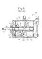
- a swash plate type compressor which is disclosed in Japanese patent publication No. 61-123779, is shown in Fig. 9.
- a compressor 100 comprises a casing 101, a rotating shaft 102, an oil chamber 103, a seal ring 104, and a mechanical seal 105.
- the casing 101 forms an outer shell of the compressor 100 and is provided with a mechanism compartment 106 inside.
- a compressing or pumping mechanism portion 110 which comprises pistons 107, a swash plate 108, cylinder bores 109, etc. is disposed in the mechanism compartment 106.
- the oil chamber 103 is disposed in an adjacent position in front of the mechanism chamber 106.
- the rotating shaft 102 which penetrates the oil chamber 103 so as to communicate the compressing or pumping mechanism portion 110 to the outside 113 is provided.
- a communicating hole 111 and a check valve 112 are disposed in an upper portion of a partition wall between the oil chamber 103 and the mechanism compartment 106. Accordingly, the oil can only flow in the direction from the oil chamber 103 side to the mechanism compartment 106 side.
- the seal ring 104 is disposed on the periphery of the rotating shaft 102 and on the partition wall between the oil chamber 103 and the mechanism compartment 106.
- the mechanical seal 105 is disposed on the periphery of the rotating shaft 102 and in a partition wall between the oil chamber 103 and the outside 113.
- the oil chamber 103 is provided in the compressor 100, as a pressure regulating chamber. That is, when the actuating fluid flows through the seal ring 104 into the oil chamber 103 from the mechanism compartment 106, the pressure in the oil chamber 103 increases. When the inside pressure in the oil chamber 103 becomes higher than that in the mechanism compartment 106 and then the pressure difference between the oil chamber 103 and the mechanism compartment 106 becomes larger than a predetermined pressure, the check valve 112 opens and the actuating fluid is discharged from the oil chamber 103 to the mechanism chamber 106. As mentioned above, the inside pressure in the oil chamber 103 is maintained so that it does not exceed the predetermined pressure. Thus, the leakage of the actuating fluid to the outside 113 is prevented.
- the pressure difference between the oil chamber 103 and the mechanism compartment 106 is always maintained below the predetermined pressure by the check valve 112. Accordingly, the oil chamber 103 is open to the mechanism compartment 106 side by the check valve 112. Thus, when the inside pressure in the oil chamber 103 increases, oil flows through the check valve 112 into the mechanism compartment 106. That is, the oil does not flow through the seal ring 104 into the mechanism compartment 106. Therefore, in a shaft seal of a conventional fluidic machine, the oil in the oil chamber 103 is used only for regulating pressure between the oil chamber 103 and the mechanism compartment 106 and it cannot be said that the sealing and the lubrication qualities which the oil has are sufficiently utilized.
- the communicating hole 111 to the check valve 112 is provided, in order to communicate the oil chamber 103 and the mechanism compartment 106. Therefore, the structure of the shaft seal device is complicated and, in particular, a shaft seal device such as the conventional one is difficult to be combined in a small compressor.
- a shaft seal device of the present invention has been developed with above-mentioned problems being taken into consideration and the purpose of the present invention is to provide a shaft seal device the structure of which is simple and which has an oil chamber able to supply oil to its shaft seal portions.
- the shaft seal device of the present invention seals the periphery of a rotating shaft of a fluidic machine that comprises a casing, inside which a mechanism compartment having a compressing or pumping mechanism portion which compresses or pumps an actuating fluid is provided, and the rotating shaft, one end of which extends from the casing to an outside and the other end of which is inserted into the mechanism compartment, and is connected to the compressing or pumping mechanism portion.
- the shaft seal device of the present invention is characterized in that it has an oil chamber that is provided within the casing and adjacent to the mechanism compartment, through which the rotating shaft penetrates and in which oil is hermetically contained, so that the oil chamber and the mechanism compartment are arranged side by side, a first shaft seal portion arranged between the oil chamber and the mechanism compartment, and a second shaft seal portion arranged between the oil chamber and the outside.
- the oil chamber is provided within the casing and adjacent to the mechanism compartment so that the oil chamber and the mechanism compartment are arranged side by side, the first shaft seal portion is arranged between the oil chamber and the mechanism compartment, and the second shaft seal portion is arranged between the oil chamber and the outside, respectively.
- the oil chamber is formed as a hermetically sealed structure filled with oil.
- the shaft seal device of the present invention only a very small clearance, which is formed in the first shaft seal portion, communicates the oil chamber to the mechanism compartment. That is, different from the shaft seal device of the conventional compressor 100 mentioned above, the communicating hole 111 and the check valve 112 are not provided. Accordingly, the pressure in the oil chamber is not regulated and the inside pressure in the oil chamber varies. Therefore, when the inside pressure in the mechanism compartment is higher than that in the oil chamber, the actuating fluid is introduced into the oil chamber. On the other hand, oil is filled in the oil chamber. Moreover, if the actuating fluid passes through the oil chamber, the second shaft seal portion is provided on the outflow side of the oil chamber, so that it is less possible that the actuating fluid leaks out to the outside.
- the oil can always be supplied from the oil chamber to the sliding contact portions by the pressure difference between the oil chamber and the mechanism compartment during both the operation condition of the fluidic machine and the stopped condition thereof.
- the oil is a liquid, it is possible to decrease the inside pressure in the oil chamber by passing only a small amount of the oil. Therefore, the amount of the oil flowing out from the oil chamber to the mechanism compartment is very small. As a result, the oil flowing into the mechanism compartment has only a little influence on the actuating fluid.
- the second shaft seal portion of the shaft seal device is formed by a mechanical seal.
- the mechanical seal has a structure such that a rotating surface and a fixed surface thereof, which are both completed in high accuracy and are arranged orthogonally to the axis, are in contact so that sliding is possible and, thereby, the fluid which should be hermetically sealed is prevented from leaking.
- the mechanical seal in comparison with other sealing devices, such as a gland packing, etc., causes a small amount of leakage of the fluid which should be hermetically sealed. Therefore, in case that the mechanical seal is used as the second shaft seal portion, even if the actuating fluid passes through the first shaft seal portion and the oil chamber, the actuating fluid can be surely restricted from leaking out to the outside.
- the first shaft seal portion of the shaft seal device is formed by a mechanical seal.
- the mechanical seal has a high sealing quality to prevent fluid from flowing from a high pressure side to a low pressure side, but, on the contrary, it has a low sealing quality to prevent the fluid from flowing from the low pressure side to the high pressure side. Therefore, when the mechanical seal is disposed so that the mechanism compartment side is in the high pressure side and the oil chamber side is in the low pressure side, the fluid is allowed to flow only in the direction from the oil chamber side to the mechanism compartment side. As a result, when the pressure in the mechanism compartment is higher than that of the oil chamber, the flow of the actuating fluid from the mechanism compartment to the oil chamber can be effectively restricted.
- At least either of the first shaft seal portion or the second shaft seal portion of the shaft seal device is formed by a lip seal which has a resilient lip contacting the rotating shaft so that sliding is possible.
- the lip seal is arranged on an inner circumferential surface of a through hole.
- the rotating shaft is arranged in the center of the inner circumferential side of the through-hole.
- the resilient lip contacts the outer circumferential surface of the rotating shaft so that sliding is possible.
- the lip seal has fewer parts than the mechanical seal. Therefore, according to this construction, the structure of the shaft seal device can be simplified. Moreover, the lip seal is more compact than the mechanical seal. As a result, according to the present construction, the shaft seal device can be miniaturized.
- the surface of the resilient lip is preferably formed by a resin.
- the resin has higher durability against materials such as dimethyl ether (DME), etc., than a rubber. That is, the resin is more difficult to be degraded than the rubber. Therefore, according to the present construction, when the fluid which should be sealed is DME, or the like, the life of the resilient lip can be extended.
- the resin is made of a fluoric resin.
- the fluoric resin has a relatively low friction coefficient. Therefore, if the surface of the resilient lips is formed by the fluoric resin, the friction coefficient of the sliding surface between the rotating shaft and the resilient lips is made lower.
- the fluoric resin has particularly higher chemical resistance than a rubber, other resins, etc. As a result, when the surface of the resilient lips is formed by the fluoric resin, the life of the resilient lip can be extended.
- the lip seal has two resilient lips and the two resilient lips are constructed so as to be bent in two directions separated apart each other and so as to contact the rotating shaft so that sliding is possible.
- the resilient lips at first, extend from the inner circumferential surface of the through hole toward the outer circumferential surface of the rotating shaft, that is, in the direction in which the diameter is reduced, and, at next, extend along the outer circumferential surface of the rotating shaft while being bent.
- two resilient lips are provided.
- the two resilient lips are arranged so as to be bent in two directions separating apart each other.
- the resilient lips have different sealing qualities with respect to flow direction of the fluid which is sealed. Therefore, when the two resilient lips are arranged so as to be bent in two directions separating apart each other, a good sealing quality in two opposite directions can be obtained.
- the lip seal has a construction in which an o-ring arranged on the inner circumferential surface of the through hole through which the rotating shaft penetrates, and a torque isolating member, which is interposed between the o-ring and the resilient lip and restricts the o-ring from rotating together with the resilient lip when the resilient lip is rotated by friction resistance created between the rotating shaft and the sliding contact surface, are provided.
- the rotating shaft is arranged in the inner circumferential side of the resilient lip.
- the o-ring is arranged on the outer circumferential side of the resilient lip. The o-ring is fixed on the inner circumferential surface of the through hole. Therefore, when the rotating shaft rotates, the resilient lip may be also rotated in some cases.
- the shaft seal device of the present construction is provided with a torque isolating member. That is, the torque isolating member prevents the o-ring from rotating and receives the shear force. Therefore, according to the present construction, the shear force acting on the o-ring is restricted. As a result, damage, to the o-ring, causing problems, such as the degradation of a sealing quality, can be prevented.
- the shaft seal device of the present invention is constructed to be applied to a piston type pump.
- the piston type pump makes the rotating force of a rotating shaft converted to a reciprocating force of pistons to compress an actuating fluid.
- the suction pressure of a pump changes less than that of a compressor, etc. Accordingly, the inner pressure change in a mechanism compartment of the pump is small. Therefore, if the shaft seal device of the present invention is applied to the piston type pump and, at the same time, the inner pressure in the oil chamber of the shaft seal device is set to be approximately equal to that in the mechanism compartment thereof, the pressure difference between the oil chamber and the mechanism compartment can be reduced. As a result, the leakage of the actuating fluid from the mechanism compartment to the oil chamber can be more effectively restricted.
- the shaft seal device of the present construction is especially preferable to be applied to a piston type pump which uses an actuating fluid such as DME, propane, or the like.
- a fuel supply system which uses, for example, DME as fuel comprises a fuel tank, a supply pump, a main pump, and an injector in that order from the upstream side.
- DME has a boiling point at -24 Celsius degree, so that it is a gas at atmospheric temperature and pressure. Therefore, DME is pressurized, liquefied, and stored in a fuel tank in a state of liquid. The liquefied DME is pumped to the main pump by the supply pump.
- sealing oil may be mixed into DME.
- DME is used as fuel, so that if the amount of the mixed sealing oil is too much, it is possible that incomplete combustion of the fuel occurs and the exhaust gas of the fuel becomes dirty. Accordingly, an increased amount of the mixed sealing oil should be prevented.
- DME has cleaning function for oil. As a result, an oil film provided in the shaft seal device is also cleaned and the amount of the oil is reduced.
- the shaft seal device of the present construction oil for the first shaft seal portion can be supplied from the oil chamber without oil being mixed into the actuating fluid, such as the DME, propane, or the like. Further, even if DME or the like removes the oil, the oil can be continuously supplied from the oil chamber to the first shaft seal portion. Moreover, if DME, or the like, flows out from the first shaft seal portion, it does not leak out to the outside as long as it does not pass through the oil chamber and the second shaft seal portion. Therefore, it is less possible that DME, or the like, leaks to the outside.
- the shaft seal device of the present construction is especially preferable to be used for a piston type pump which uses DME, propane, or the like as the actuating fluid.
- the embodiments of a shaft seal device of the present invention are described below.
- the shaft seal device of the present embodiments is used for a swash plate pump of an axial piston type which is a supply pump for DME.
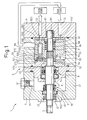
- a pump 1 comprises a casing 2 and a rotating shaft 3.
- the casing 2 comprises a front housing 4, a partition wall 46, a cylinder housing 5, and a rear housing 6.
- the front housing 4 is composed of a disc-shaped end plate 40 and a side circumferential wall 41 having a tubular shape and extending in the rear direction from a circumferential edge of the end plate 40. That is, the front housing 4 has a cup-shaped opening directed to the rear side.
- a through hole 42 which runs in a direction from the front to the rear is provided.
- a bearing 43 is disposed in the front portion of an inner circumferential surface of the through hole 42 .
- a second shaft seal portion 7 which constitutes the shaft seal device is disposed. The second shaft seal portion 7 is described later.
- the disk-shaped partition wall 46 is disposed so as to close an opening in the front housing 4.
- An oil chamber 8 which constitutes the shaft seal device is formed by being surrounded by the front housing 4 and the partition wall 46.
- the oil chamber 8 is described later.
- a through hole 47 which passes in a direction from the front to the rear is provided.
- a first shaft seal portion 9 which constitutes the shaft seal device is disposed.
- the first shaft seal portion 9 is described later.
- an intermediate portion of the rotating shaft 3 is interposed.
- the cylinder housing 5 is disposed in the rear side of the partition wall 46.
- the cylinder housing 5 has a cylindrical shape extending in a direction from the front to the rear.
- a mechanism chamber 50 is formed within the cylinder housing 5.
- a compressing or pumping mechanism portion 51 which compresses and pumps DME is arranged in the mechanism chamber 50.
- the compressing or pumping mechanism portion 51 comprises a fixed swash plate 52, a slipper retainer 53, a pivot 54, a cylinder block 55, pistons 56, slippers 57, a coil spring 58, and a bush pin 59.
- the fixed swash plate 52 has a thick disc shape which has a front end surface 520, which is a circular surface perpendicular to the rotating shaft 3, and a rear end surface 521, which is an elliptical surface inclined against the rotating shaft 3.
- the rotating shaft 3 passes through a central through hole in the fixed swash plate 52 in a direction from the front to the rear.
- the pivot 54 which has an outer circumferential surface with a spherical shape is inserted so as to surround the rotating shaft 3.
- a spline 30 is provided on an outer circumferential surface of the rotating shaft 3 which is positioned in a more rear position than that of the pivot 54.
- the lotus-root shaped cylinder block 55 is inserted into an outer circumferential side of the spline 30 so that it can rotate together with the rotating shaft 3.
- a collar-shaped front spacer 31 and a rear spacer 32 with the same shape as the front spacer 31, which are spaced apart each other is inserted so as to surround the rotating shaft 3.
- a coil spring 58 are interposed between the front spacer 31 and the rear spacer 32.
- a rod-shaped bush pin 59 is interposed between the front spacer 31 and the pivot 54. That is, the pivot 54 is biased forward by the coil spring 58 through the front spacer 31 and the bush pin 59.
- the disc-shaped slipper retainer 53 is inserted so as to surround the pivot 54 so that swinging is possible.
- On an outer circumferential portion of the slipper retainer 53 a plurality of insertion holes 530 are provided with a same interval in a specific angle. Slippers 57 are inserted into the insertion holes 530 from the front.
- An opening portion 572 which opens backward and has a inner circumferential surface having a reverse spherical shape is provided on a rear end surface of the slipper 57.
- a front end surface 573 of the slipper 57 comes into contact with the rear end surface 521 of the fixed swash plate 52.
- Cylinder bores 550 which open forward are arranged in an outer circumference of the cylinder block 55 with a same interval in a specific angle.
- the pistons 56 are inserted into the cylinder bores 550.
- An end portion 560 of each piston 56 has a spherical shape.
- the front end portions 560, with spherical shapes, of the pistons 56 are coupled into the opening portions 572 of the slippers 57 so as to be able to move.
- a port plate 551 is disposed in a rear side of the cylinder block 55.
- the port plate 551 has a disc shape.
- an almost half-circle shaped suction port 552 and a similarly almost half-circle shaped discharge port 553 are provided so that they penetrate through the port plate 551 in a direction from the front to the rear.
- a drain port 500 which is connected to a fuel tank is provided so that it penetrates through the cylinder housing 5 in a vertical direction (a direction from the top to the bottom).
- the rear housing 6 is disposed in a rear side of the cylinder housing 5.
- the rear housing 6 has a disc shape.
- a cup-shaped bearing portion 60 which has an opening in its front portion is provided on the front end surface of the rear housing 6.
- a bearing 61 is disposed in an inner circumferential side of the bearing portion 60.
- the rear end of the rotation shaft 3 is inserted at a more inner circumferential side than the bearing 61 and is supported by the bearing 61.
- a suction passage 62 and a discharge passage 63 which pass through in a direction from the front to the rear are provided in the rear housing 6, respectively.
- the front end of the suction passage 62 is connected to the suction port 552.
- the rear end of the suction passage 62 is connected to the fuel tank.
- the front end of the discharge passage 63 is connected to the discharge port 553.
- the rear end of the discharge passage 63 is connected to a main pump which pumps fuel to an injector.
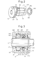
- FIG. 2 is the figure which shows the principle of the pump shown in FIG. 1.
- the members, in FIG. 2, corresponding to FIG. 1 are denoted by the same reference characters and numbers in FIG. 1.
- Members which are static in the figure are the fixed swash plate 52 and the port plate 551.
- Other members are rotated in the direction indicated by an arrow in the figure by a rotation force of the rotating shaft 3 transferred through the spline 30.
- the rear end surface 521 of the fixed swash plate 52 is inclined against the rotating shaft 3.
- the slippers 57 rotate while they slide on the rear end surface 521.
- the pistons 56 connected to the slippers 57 rotate so that they draw elliptical lines in a direction inclining against axial line from the front to the rear. Due to the reciprocating motion of the pistons 56 in a direction from the front to the rear, DME is sucked and compressed in the cylinder bores 550 formed in the cylinder block 55.
- DME is sucked, while the pistons 56 rotate and pass the near side in the figure. In that case, the pistons 56 move from the right side to the left side in the figure. DME is then drawn from the fuel tank through the suction port 552 formed in the port plate 551.
- DME is discharged while the pistons 56 rotate and pass the far side in the figure. In that case, the pistons 56 move from the left side to the right side in the figure. DME is then discharged to the main pump through the discharge port 553 formed in the port plate 551. Thus as described above, the pump draws and discharges DME.
- the shaft seal device of the present embodiment comprises the first shaft seal portion 9, the oil chamber 8, and the second shaft seal portion 7, shown in FIG. 1.
- FIG. 3 shows an enlarged view of the first shaft seal portion 9.
- the members, in FIG. 3, corresponding to FIG. 1 are denoted by the same reference characters and numbers in FIG. 1.
- the first shaft seal portion 9 is a mechanical seal.
- the first shaft seal portion 9 comprises a fixed side member 90 and a rotating side member 91.
- the fixed side member 90 comprises a seal ring 900, a rubber ring 901, and a seat ring 902.
- the seal ring 900 is attached to a stepped portion from a small diameter side to a large diameter side, in the through hole 47 of the partition wall 46.
- the rubber ring 901 is attached to an inner circumferential surface of a large diameter side in the through hole 47 of the partition wall 46.
- the seat ring 902 is fixed by inserting into the inner circumferential side of the rubber ring 901 and in the rear side of the seal ring 900.
- the rear end surface of the seat ring 902 is formed as a fixed surface 903 which contacts the rotating side member 91 so that sliding is possible.
- the rotating side member 91 comprises a spring holder 910, a coil spring 911, a shaft packing 912, a sliding ring 913, and a rubber ring 914.
- the spring holder 910 has a shape like a collar and is fixed so that it comes into contact with a step portion 300 of the rotating shaft 3.
- a mechanical seal disposed in the first shaft seal portion 9 has a diameter larger than that of a mechanical seal disposed in the second shaft seal portion 7, because the mechanical seal in the first shaft seal portion 9 is positioned on the rotating shaft 3 after it passes over a step portion supporting a spring holder of the second shaft seal portion 7.
- the coil spring 911 is arranged so as to be inserted on and surround the rotating shaft 3.
- the collar-shaped rubber shaft packing 912 is arranged so as to be inserted on and surround the rotating shaft 3.
- the sliding ring 913 is arranged via the rubber ring 914 so as to be inserted on and surround the rotating shaft 3.
- the front end surface of the sliding ring 913 is provided with a sliding surface 915 which contacts the fixed surface 903 so that sliding is possible.
- the second shaft seal portion 7 is a mechanical seal which is same as the first shaft seal portion 9. Therefore, an explanation of the construction of the second shaft seal portion 7 is omitted.
- the oil chamber 8 will be described. As shown in FIG. 1, the oil chamber 8 is provided between the first shaft seal portion 9 and the second shaft seal portion 7. The oil chamber 8 is filled with oil through the oil filling port 44. The oil chamber 8 is hermetically closed by the oil filling plug 45.
- a rotating side member 70 of the second shaft seal portion 7 is disposed within the oil chamber 8. Accordingly, a sliding surface 700 is always supplied with oil in the oil chamber 8. Therefore, the sealing and lubrication qualities of the sliding surface 700 are kept in a good condition. For these reasons, there is little possibility for DME to pass through both the oil chamber 8 and the second shaft seal portion 7. As a result, it is less possible for DME to leak out to the outside.
- the oil flowing into the mechanism compartment 50 is recovered from the drain port 500 and flows into the fuel tank. Accordingly, it is less possible for the oil to be supplied to the main pump directly though the discharge passage 63 together with the fuel DME. Therefore, it is possible to prevent the oil density in the fuel DME from being raised suddenly and rapidly. Due to the temperature change, the pressure in the oil chamber 8 is varied and, in the case of a liquid such as DME, the pressure in the mechanism compartment 50 side is also varied due to the temperature change, similarly. As a result, the pressure in the oil chamber 8 side never raises considerably higher than that in the mechanism compartment 50 side.
- the second embodiment of the shaft seal device of the present invention will be described.
- the construction of a pump which comprises a shaft seal device of the present embodiment is similar as the first embodiment, as shown in FIG. 4.
- the members, in FIG. 4, corresponding to the members in FIG. 1 are denoted with the same reference characters and numbers in FIG. 1.
- the different point of the present embodiment from the first embodiment is that a first shaft seal portion 10 of the shaft seal device is made of an oil seal.
- the first shaft seal portion 10 is made of an oil seal, the length of the pump 1 in a direction from the front to the rear can be shortened. Therefore, according to the present embodiment the pump 1 can be miniaturized.
- the shaft seal device of the present embodiment comprises a first shaft seal portion 10, an oil chamber 8, and a second shaft seal portion 7 in FIG. 4.
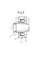
- FIG. 5 shows an enlarged view of the first shaft seal portion.
- the members, in FIG. 5, corresponding to the members in FIG. 4 are denoted with the same reference characters and numbers in FIG. 4.
- the first shaft seal portion 10 is an oil seal.
- the first oil seal portion 10 has a shape having double cylinders which open backward.
- a cylindrical inserting portion 11 which is inserted into the inner circumferential surface of the through hole 47 in the partition wall portion 46, is arranged.
- a dust lip 13 which resiliently contacts the rotating shaft 3 is arranged in the front portion of the inner circumferential cylinder side of the first shaft seal portion 10.
- a ring spring 15 which biases and tightens the main lip 14 toward the rotating shaft 3 is inserted at the back surface of the main lip 14 opposite to the rotating shaft 3 so that it surrounds the rotating shaft 3.
- a metallic ring 16 is integrally installed inside the first shaft seal portion 10 so that it is embedded therein.
- the oil flowing into the mechanism compartment 50 is recovered from the drain port 500 and flows into the fuel tank. Accordingly, it is less possible for the oil to be supplied to the main pump directly though the discharge passage 63 together with the fuel DME. Therefore, it is possible to prevent the oil density in the fuel DME from being raised suddenly and rapidly.
- the third embodiment of the shaft seal device of the present invention will be described.
- the construction of a pump which comprises a shaft seal device of the present embodiment is similar as the first embodiment, as shown in FIG. 6.
- the members, in FIG. 6, corresponding to the members in FIG. 1 are denoted with the same reference characters and numbers as in FIG. 1.
- the different point of the present embodiment from the first embodiment is that a first shaft seal portion 200 and a second shaft seal portion 600 of the shaft seal device is made of a lip seal. Therefore, in this description, only the different point is described.
- FIG. 7 shows an enlarged view of a first shaft seal portion 200 of a shaft seal device of the present embodiment.
- the first shaft seal portion 200 comprises an o-ring 202, an outer annular member 203, a front side resilient lip 204, a rear side resilient lip 205, an inner annular member 206, and a stopper ring 207.
- the outer annular member 203 is included in a torque isolating member of the present invention.
- the o-ring 202 which is made of a rubber is arranged in a first ring groove 470 which is provided in the through hole 47.
- the outer annular member 203 has a cup shape which has a hole in a bottom wall 208 and opens backward.
- the outer annular member 203 is pressed into the through hole 47 until the bottom wall 208 comes into contact with a step portion 471, and cannot relatively rotate.
- the outer annular member 203 then presses the o-ring 202 from the inner circumferential side.
- the inner annular member 206 similar to the outer annular member 203, has a cup shape which has a hole in a bottom wall 209 and opens backward.
- the inner annular member 206 has a diameter smaller than that of the outer annular member 203.
- the inner annular member 206 is arranged in the inner circumferential side of the outer annular member 203.
- the bottom wall 208 of the outer annular member 203 is spaced apart from the bottom wall 209 of the inner annular member 206, in a direction from the front to the rear.
- the front side resilient lip 204 and the rear side resilient lip 205 are interposed between the both bottom walls 208 and 209.
- the front side resilient lip 204 is made of PTFE and has a ring shape.
- the front side resilient lip 204 is bent forward and contacts the rotating shaft 3 so that sliding is possible.
- the rear side resilient lip 205 similar to the front side resilient lip 204, is made of PTFE and has a ring shape.
- the rear side resilient lip 204 is bent backward to the contrary of the front side resilient lip 204, and contacts the rotating shaft 3 so that sliding is possible.
- the stopper ring 207 is inserted into a second ring groove 472 provided in the through hole 47. The stopper ring 207 engages with the rear ends of the outer annular member 203 and the inner annular member 206 and fixes them.
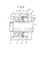
- FIG. 8 shows an enlarged view of a second shaft seal portion 600 of a shaft seal device of the present embodiment.
- the second shaft seal portion 600 comprises an o-ring 602, an outer annular member 603, a retaining ring 604, a resilient lip 605, an inner annular member 606, and a stopper ring 607.
- the outer annular member 603 is included in a torque isolating member of the present invention.
- the o-ring 602 which is made of a rubber is arranged in a first ring groove 420 which is provided in the through hole 42.
- the outer annular member 603 has a cup shape which has a hole in a bottom wall 608 and opens backward.
- the outer annular member 603 is pressed into the through hole 42 until the bottom wall 608 comes into contact with a step portion 671, and cannot relatively rotate.
- the outer annular member 603 then presses the o-ring 602 from the inner circumferential side.
- the retaining ring 604 is arranged in the inner circumferential side of the outer annular member 603.
- the retaining ring 604 is adjacent to the bottom wall 608.
- the inner annular member 606, similar to the outer annular member 603, has a cup shape which has a hole in a bottom wall 609 and opens backward.
- the inner annular member 606 has a diameter smaller than that of the outer annular member 603.
- the inner annular member 606 is arranged in the inner circumferential side of the outer annular member 603.
- the retaining ring 604 is spaced apart from the bottom wall 609 of the inner annular member 606, in a direction from the front to the rear.
- the resilient lip 605 is interposed between the retaining ring 604 and the bottom wall 609.
- the resilient lip 605 is made of PTFE and has a ring shape.
- the resilient lip 605 is bent backward and contacts the rotating shaft 3 so that sliding is possible.
- the stopper ring 607 is inserted into a second ring groove 422 provided in the through hole 42. The stopper ring 607 engages with the rear ends of the outer annular member 603 and the inner annular member 606 and fixes them.
- the first shaft seal portion 200 and the second shaft seal portion 600 are lip seals. Therefore, the seal construction thereof is simple in comparison with a mechanical seal. Moreover, it is compact in comparison with a mechanical seal.
- a shaft seal device which uses a lip seal
- the rotating portion is only the rotating shaft 3 and the amount of heat, which is generated by stirring oil or DME, is small.
- the construction in which a lip seal is used for the second shaft seal portion has no step portion, so that the diameter of the rotating shaft 3 at the first shaft seal portion is not required to be increased. Accordingly, it is possible for the diameter of the rotating shaft 3 to be reduced, and thereby the radius of sliding movement thereof is decreased, so that it is possible to decrease heat generation.
- the front side resilient lip 204, the rear side resilient lip 205, and the resilient lip 605 are made of PTFE, respectively. Therefore, they have high durability against the fuel DME.
- the first shaft seal portion 200 in the present construction comprises the front side resilient lip 204 bent forward and the rear side resilient lip 205 bent backward.
- the rear side resilient lip 205 prevents DME from flowing into the oil chamber 8.
- the front side resilient lip 204 prevents oil from flowing into the mechanism chamber 50. Therefore, the present construction has a good sealing quality against the DME leakage from the mechanism chamber 50 to the oil chamber 8 and against the oil leakage from the oil chamber 8 to the mechanism chamber 50.
- the second shaft seal portion 600 in the present construction also comprises the resilient lip 605 bent backward. Therefore, the present construction has a good sealing quality against the oil leakage from the oil chamber 8 to the outside.
- the type of the mechanical seals used for the first shaft seal portion 9 and the second shaft seal portion 7 is not particularly limited. Either seal of a balance type or an unbalance type may be chosen. An inside mounting type or an outside mounting type may be chosen. Moreover, a plurality of mechanical seals may be used so as to be aligned in series.
- the type of the oil seal used for the first shaft seal portion 10 is not particularly limited.
- One, which does not have the dust lip 13, the ring spring 15, and/or the metallic ring 16, may be used.
- the constructions of the first shaft seal portion 9 and 10, and the second shaft seal portion 7 are also not particularly limited. An embodiment in which a gland packing or the like is used may be realized.
- the construction of the lip seals used for the first shaft seal portion 200 and the second shaft seal portion 600 is not particularly limited.
- it may have a construction in which additional dust lips are provided.
- a sheet of a dust lip may be disposed in the first shaft seal portion 200.
- Two sheets of a dust lip may also be disposed in the second shaft seal portion 600.
- the resilient lip may be made of another fluoric resin other than PTFE.
- tetrafluoroethylene perfluoroalkylvinylether copolymer PFA
- FEP tetrafluoroethylene hexafluoropropylene copolymer
- PCTFE polychlorotrifluoroethylene
- EECTFE tetrafluoroethylene ethylene copolymer
- ECTFE chlorotrifluoroethylene ethylene copolymer
- PVDF polyvinylidene fluoride
- PVF polyvinyl fluoride
- PVF polyvinyl fluoride
- the bearing 43 in the above-mentioned embodiment is arranged in the oil chamber 8 may be realized.
- lubricating grease for the bearing 43 can be substituted for the oil in the oil chamber 8.
- the shaft seal device is installed in a swash plate pump of an axial piston type, but it may be installed in another types of pumps or fluidic machines, such as a compressor etc., other than a pump.
- DME is used as the actuating fluid, but another fluids, such as propane etc., may be used.
- a shaft seal device the construction of which is simple and which has an oil chamber capable of supplying oil to shaft seal portions, can be provided.
Landscapes
- Engineering & Computer Science (AREA)
- Mechanical Engineering (AREA)
- General Engineering & Computer Science (AREA)
- Compressor (AREA)
- Details Of Reciprocating Pumps (AREA)
- Sealing With Elastic Sealing Lips (AREA)
- Sealing Of Bearings (AREA)
- Structures Of Non-Positive Displacement Pumps (AREA)
- Applications Or Details Of Rotary Compressors (AREA)
Applications Claiming Priority (4)
| Application Number | Priority Date | Filing Date | Title |
|---|---|---|---|
| JP2001229323 | 2001-07-30 | ||
| JP2001229323 | 2001-07-30 | ||
| JP2002006662 | 2002-01-15 | ||
| JP2002006662A JP2003113780A (ja) | 2001-07-30 | 2002-01-15 | 軸封装置 |
Publications (2)
| Publication Number | Publication Date |
|---|---|
| EP1281865A2 true EP1281865A2 (fr) | 2003-02-05 |
| EP1281865A3 EP1281865A3 (fr) | 2004-08-18 |
Family
ID=26619527
Family Applications (1)
| Application Number | Title | Priority Date | Filing Date |
|---|---|---|---|
| EP02016157A Withdrawn EP1281865A3 (fr) | 2001-07-30 | 2002-07-20 | Système d'étanchéité de l'arbre pour un compresseur |
Country Status (3)
| Country | Link |
|---|---|
| US (1) | US20030020240A1 (fr) |
| EP (1) | EP1281865A3 (fr) |
| JP (1) | JP2003113780A (fr) |
Cited By (2)
| Publication number | Priority date | Publication date | Assignee | Title |
|---|---|---|---|---|
| AT501235A1 (de) * | 2004-11-23 | 2006-07-15 | Hoerbiger Automatisierungstech | Hydraulisches kombinationsaggregat |
| EP3276173A1 (fr) * | 2016-07-27 | 2018-01-31 | Mitsubishi Heavy Industries Thermal Systems, Ltd. | Joint d'arbre de réfrigérant et compresseur de réfrigérant ouvert équipé d'un joint d'arbre de réfrigérant |
Families Citing this family (7)
| Publication number | Priority date | Publication date | Assignee | Title |
|---|---|---|---|---|
| JP4066633B2 (ja) | 2001-10-09 | 2008-03-26 | 株式会社豊田自動織機 | 流体加圧ポンプおよび流体タンクユニット |
| CN110500271A (zh) * | 2018-05-16 | 2019-11-26 | 北京中冶华润科技发展有限公司 | 压油机构和泵油装置 |
| CN110388154A (zh) * | 2019-08-02 | 2019-10-29 | 沈阳铁能通讯智能技术有限公司 | 一种安装于水密门的转把通门密封件及其制备方法 |
| CN112178189A (zh) * | 2020-10-10 | 2021-01-05 | 江门市新会区天府密封科技有限公司 | 一种单端面机械密封装置 |
| JP7175428B1 (ja) * | 2021-03-30 | 2022-11-18 | Nok株式会社 | 密封構造および密封方法 |
| KR102559250B1 (ko) * | 2023-01-04 | 2023-07-26 | (주)일신오토클레이브 | 실링 카트리지 및 이를 구비하는 실링구 커버 |
| CN119308816B (zh) * | 2024-10-30 | 2025-10-31 | 江苏师范大学 | 一种增压比可变的轴向柱塞式液压增压器 |
Family Cites Families (31)
| Publication number | Priority date | Publication date | Assignee | Title |
|---|---|---|---|---|
| US2610872A (en) * | 1948-10-06 | 1952-09-16 | Dynamatic Corp | Shaft seal |
| US3499388A (en) * | 1967-06-13 | 1970-03-10 | Hale Fire Pump Co | Centrifugal pump |
| US3521890A (en) * | 1968-10-07 | 1970-07-28 | Thiokol Chemical Corp | Quick change lip seal cartridge device |
| US3771799A (en) * | 1971-08-20 | 1973-11-13 | Mather Co | Multi-element fluctuating pressure seal |
| US3951417A (en) * | 1973-10-03 | 1976-04-20 | Vitaly Petrovich Chernykh | Rotary shaft end seal for apparatus operating under pressure |
| US3945765A (en) * | 1974-04-15 | 1976-03-23 | Sankyo Electric Co., Ltd. | Refrigerant compressor |
| US3938811A (en) * | 1974-10-11 | 1976-02-17 | Kommanditbolaget United Stirling (Sweden) Ab & Co. | Sealing means for stirling engine crankcases |
| US4156531A (en) * | 1976-10-04 | 1979-05-29 | Esco Transmissions | Sealing ring for flexible toothed coupling and couplings provided with such rings |
| SE404414B (sv) * | 1977-02-25 | 1978-10-02 | Alfa Laval Ab | Anordning for att diska en forsta tetningsring och ett utrymme nermast intill tetningsringen |
| US4155560A (en) * | 1977-11-23 | 1979-05-22 | Garlock Inc. | Water pump seal and method |
| US4491330A (en) * | 1983-08-01 | 1985-01-01 | Franklin Electric Co., Inc. | Rotary lip seal |
| JPS61123779A (ja) * | 1984-11-19 | 1986-06-11 | Atsugi Motor Parts Co Ltd | 圧縮機の軸封装置 |
| US4755115A (en) * | 1984-11-21 | 1988-07-05 | Atsugi Motor Parts Company, Limited | Shaft seal assembly for compressor |
| KR890004033B1 (ko) * | 1985-04-16 | 1989-10-16 | 에누오우케이 가부시끼가이샤 | 레이디얼 오일 시일 |
| JPH028565A (ja) * | 1988-01-11 | 1990-01-12 | Taiho Kogyo Co Ltd | リップシール装置 |
| JPS6430975A (en) * | 1987-07-24 | 1989-02-01 | Taiho Kogyo Co Ltd | Lip seal device |
| US4834397A (en) * | 1988-05-20 | 1989-05-30 | Taiho Kogyo Co., Ltd. | Lip seal device having an annular groove |
| US4861045A (en) * | 1988-06-16 | 1989-08-29 | Mather Seal Company | Dust excluder for vehicle air conditioning compressor seal assembly |
| JPH02154868A (ja) * | 1988-12-03 | 1990-06-14 | Toyota Autom Loom Works Ltd | 可変容量型揺動斜板式圧縮機におけるクランク室のシール構造 |
| US5024364A (en) * | 1989-02-13 | 1991-06-18 | Federal-Mogul Corporation | Unitized oil seal and method of making a unitized oil seal |
| US5052696A (en) * | 1990-10-26 | 1991-10-01 | Mather Seal Company | Compact compressor seal |
| US5326111A (en) * | 1991-07-19 | 1994-07-05 | Mather Seal Company | Separately bonded elastomeric sleeve for seal casing |
| US5174250A (en) * | 1991-12-27 | 1992-12-29 | Caterpillar Inc. | Dual seal pump |
| US5209502A (en) * | 1992-06-23 | 1993-05-11 | Mather Seal Company | Dual lip seal and method of forming the seal |
| JP3232544B2 (ja) * | 1993-11-24 | 2001-11-26 | 株式会社豊田自動織機 | 車両空調用圧縮機の堰構造 |
| JP2843280B2 (ja) * | 1995-09-29 | 1999-01-06 | アイシン精機株式会社 | ウォータポンプ |
| CN1125932C (zh) * | 1996-07-17 | 2003-10-29 | 株式会社丰田自动织机制作所 | 压缩机的轴封结构 |
| BE1010915A3 (nl) * | 1997-02-12 | 1999-03-02 | Atlas Copco Airpower Nv | Inrichting voor het afdichten van een rotoras en schroefcompressor voorzien van dergelijke inrichting. |
| US6315296B1 (en) * | 1997-09-25 | 2001-11-13 | Transcom, Inc. | Flangeless retrofittable severe duty seal for a shaft |
| DE19809768C2 (de) * | 1998-03-06 | 2000-01-05 | Aisin Seiki | Ölversorgungsvorrichtung |
| US6257587B1 (en) * | 1999-05-21 | 2001-07-10 | Federal-Mogul World Wide, Inc. | Radial lip seal having protected porous dust excluder |
-
2002
- 2002-01-15 JP JP2002006662A patent/JP2003113780A/ja active Pending
- 2002-07-20 EP EP02016157A patent/EP1281865A3/fr not_active Withdrawn
- 2002-07-25 US US10/205,170 patent/US20030020240A1/en not_active Abandoned
Cited By (3)
| Publication number | Priority date | Publication date | Assignee | Title |
|---|---|---|---|---|
| AT501235A1 (de) * | 2004-11-23 | 2006-07-15 | Hoerbiger Automatisierungstech | Hydraulisches kombinationsaggregat |
| AT501235B1 (de) * | 2004-11-23 | 2006-12-15 | Hoerbiger Automatisierungstech | Hydraulisches kombinationsaggregat |
| EP3276173A1 (fr) * | 2016-07-27 | 2018-01-31 | Mitsubishi Heavy Industries Thermal Systems, Ltd. | Joint d'arbre de réfrigérant et compresseur de réfrigérant ouvert équipé d'un joint d'arbre de réfrigérant |
Also Published As
| Publication number | Publication date |
|---|---|
| US20030020240A1 (en) | 2003-01-30 |
| JP2003113780A (ja) | 2003-04-18 |
| EP1281865A3 (fr) | 2004-08-18 |
Similar Documents
| Publication | Publication Date | Title |
|---|---|---|
| KR101287428B1 (ko) | 유체 분사 시스템을 구비한 컴프레서 | |
| KR100345952B1 (ko) | 부스터 펌프 | |
| US6264438B1 (en) | Reciprocating pump having a ball drive | |
| KR100268317B1 (ko) | 압축기의 축 밀봉구조 | |
| JPH0637874B2 (ja) | 可変容量圧縮機 | |
| US20030020240A1 (en) | Shaft seal device having shaft seal portions with good sealing and lubrication qualities | |
| JPH09112408A (ja) | 燃料ポンプ | |
| EP0795687B1 (fr) | Pompe à piston alternatif | |
| US6368071B1 (en) | High pressure fuel pump | |
| JP2001280221A (ja) | 等圧化シャトルを有するポンプシャフトのシール | |
| JPH10176625A (ja) | プランジャポンプ | |
| US20050265862A1 (en) | Pump | |
| JP2000073969A (ja) | スクロール式流体機械 | |
| KR102073110B1 (ko) | 가변 사판식 압축기용 토출체크밸브 | |
| JP3234506B2 (ja) | 燃料ポンプ | |
| JP4153618B2 (ja) | プランジャ式ポンプ | |
| JP2002147363A (ja) | ベローズ式ポンプ装置 | |
| US20030145835A1 (en) | Drive shaft seal for gasoline direct injection pump | |
| EP1772627B1 (fr) | Système d'étanchéité pour compresseur | |
| JPH0544640A (ja) | 斜板式圧縮機 | |
| JPH0925881A (ja) | 高圧ガソリンポンプ | |
| JP3351156B2 (ja) | 燃料ポンプ | |
| JP3186322B2 (ja) | 片側ピストン式可変容量圧縮機における潤滑構造 | |
| JP2003148326A (ja) | シリンダ装置およびアキシャルピストンポンプ | |
| EP0971128A2 (fr) | Compresseur volumétrique pour réfrigérant avec système de séparation d'huile et de lubrification |
Legal Events
| Date | Code | Title | Description |
|---|---|---|---|
| PUAI | Public reference made under article 153(3) epc to a published international application that has entered the european phase |
Free format text: ORIGINAL CODE: 0009012 |
|
| 17P | Request for examination filed |
Effective date: 20020720 |
|
| AK | Designated contracting states |
Designated state(s): AT BE BG CH CY CZ DE DK EE ES FI FR GB GR IE IT LI LU MC NL PT SE SK TR |
|
| AX | Request for extension of the european patent |
Extension state: AL LT LV MK RO SI |
|
| PUAL | Search report despatched |
Free format text: ORIGINAL CODE: 0009013 |
|
| AK | Designated contracting states |
Kind code of ref document: A3 Designated state(s): AT BE BG CH CY CZ DE DK EE ES FI FR GB GR IE IT LI LU MC NL PT SE SK TR |
|
| AX | Request for extension of the european patent |
Extension state: AL LT LV MK RO SI |
|
| RIC1 | Information provided on ipc code assigned before grant |
Ipc: 7F 16J 15/32 B Ipc: 7F 04B 27/10 A |
|
| AKX | Designation fees paid |
Designated state(s): AT DE FR NL SE |
|
| STAA | Information on the status of an ep patent application or granted ep patent |
Free format text: STATUS: THE APPLICATION IS DEEMED TO BE WITHDRAWN |
|
| 18D | Application deemed to be withdrawn |
Effective date: 20060223 |