EP1281897B1 - Soupape flexible - Google Patents
Soupape flexible Download PDFInfo
- Publication number
- EP1281897B1 EP1281897B1 EP02254874A EP02254874A EP1281897B1 EP 1281897 B1 EP1281897 B1 EP 1281897B1 EP 02254874 A EP02254874 A EP 02254874A EP 02254874 A EP02254874 A EP 02254874A EP 1281897 B1 EP1281897 B1 EP 1281897B1
- Authority
- EP
- European Patent Office
- Prior art keywords
- valve
- stopper
- fluid
- needle
- lip
- Prior art date
- Legal status (The legal status is an assumption and is not a legal conclusion. Google has not performed a legal analysis and makes no representation as to the accuracy of the status listed.)
- Expired - Lifetime
Links
Images


Classifications
-
- F—MECHANICAL ENGINEERING; LIGHTING; HEATING; WEAPONS; BLASTING
- F16—ENGINEERING ELEMENTS AND UNITS; GENERAL MEASURES FOR PRODUCING AND MAINTAINING EFFECTIVE FUNCTIONING OF MACHINES OR INSTALLATIONS; THERMAL INSULATION IN GENERAL
- F16K—VALVES; TAPS; COCKS; ACTUATING-FLOATS; DEVICES FOR VENTING OR AERATING
- F16K15/00—Check valves
- F16K15/14—Check valves with flexible valve members
- F16K15/144—Check valves with flexible valve members the closure elements being fixed along all or a part of their periphery
- F16K15/145—Check valves with flexible valve members the closure elements being fixed along all or a part of their periphery the closure elements being shaped as a solids of revolution, e.g. cylindrical or conical
-
- B—PERFORMING OPERATIONS; TRANSPORTING
- B41—PRINTING; LINING MACHINES; TYPEWRITERS; STAMPS
- B41J—TYPEWRITERS; SELECTIVE PRINTING MECHANISMS, i.e. MECHANISMS PRINTING OTHERWISE THAN FROM A FORME; CORRECTION OF TYPOGRAPHICAL ERRORS
- B41J2/00—Typewriters or selective printing mechanisms characterised by the printing or marking process for which they are designed
- B41J2/005—Typewriters or selective printing mechanisms characterised by the printing or marking process for which they are designed characterised by bringing liquid or particles selectively into contact with a printing material
- B41J2/01—Ink jet
- B41J2/17—Ink jet characterised by ink handling
- B41J2/175—Ink supply systems ; Circuit parts therefor
- B41J2/17596—Ink pumps, ink valves
Definitions
- the present invention relates generally to valves for controlling fluid flow, and more particularly to valves formed of an elastomeric material.
- Fluidic valves are well known in the art, and are utilized in a wide range of applications. For example, fluidic valves are often utilized to control ink flow in printer systems. Fluidic valves may range from simple, inexpensive one-part structures to complex assemblies.
- Inexpensive valves may be simple non-loaded structures or slightly more complex interface-reliant valves.
- the non-loaded type such as "duckbill” valves, are prone to leaking at small pressure differences across the valve.
- the interface-reliant type such as "umbrella” valves, require a sealing surface other than the valve itself, which requires additional components to make the seal with mating components.
- Another interface-reliant valve is the slit septum type, in which a needle penetrates a normally closed septum to establish fluid flow. This type of valve is often prone to leaks and requires a high degree of alignment between the needle and valve. Assuring precise alignment often adds cost to a fluid system.
- EP-A-1 000 753 describes valve arrangement for ink-jet printing apparatus wherein a resilient elastic packing member bears on the central region of the end face of a valve member. Insertion of a needle causes the packing member and the valve member to separate, thereby permitting ink to flow into the needle.
- Embodiments of the present invention comprise one-part elastomeric valves which are manipulated after molding to preload the valve seal.
- the valves maintain positive seal until a fluidic pressure or mechanical force is applied to open the valve.
- the valves return to a closed state after the pressure or force is removed.
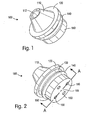
- Figs. 1 and 2 are front and rear perspective views, respectively, of an exemplary embodiment of the valve 100 of the present invention, shown before the valve has been manipulated for preloading.
- the valve is preferably integrally molded of a low durometer elastometer.
- the valve comprises a lip portion 110; a first mounting seal 120; a mounting groove 130; a second mounting seal 140; and a rear portion 150 including a plurality of fluid passages 160.
- the rear portion also includes a stopper member 155, which is further discussed with respect to Fig. 3 below.
- the lip portion 110 of the valve is formed as a truncated cone with an orifice 112; the lip is later manipulated to provide a preloaded seal, as also discussed below.
- the preferred material for forming the valve is an EPDM (ethylene polypropylene diene monomer)/butyl blend with a durometer of approximately 50-70.
- EPDM ethylene polypropylene diene monomer
- Other resilient elastomeric materials such as silicone rubber, may also be used. The material characteristics will vary with the specific design and intended application of the valve.
- Fig. 3 is a cross sectional view of an exemplary embodiment of the valve of the present invention along line A--A of Fig. 2.
- Stopper member 155 extends forward with a cylindrical wall 158 and a contact face 157.
- the conical lip 110 is pushed into the orifice 112 until the inverted lip forms a seal with the cylindrical wall 158 of the stopper, as shown in Fig 4.
- Fig. 4 is a cross sectional view of an exemplary embodiment of the valve of the present invention after preloading and installation.
- a fluid system such as an ink delivery system in a printer
- the exemplary embodiment of the valve is inserted into a round opening formed in a flat surface 210, such as the wall of an ink container.
- the first and second mounting seals 120 and 140 contact the two sides of the flat surface 210, providing fluid tight seals.
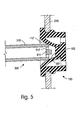
- Fig. 5 is a cross sectional view of an exemplary embodiment of the valve of the present invention showing a hollow needle 310 beginning to engaging the valve and sealing to the valve lip 110'.
- the hollow needle may typically be made of molded plastic, with one or more openings 312 at the tip for fluid flow, and a protuberance 314 for engaging the contact face 157 of the valve.
- valve design over previous "slit septum" designs is that it enables the use of relatively inexpensive plastic needles.
- the needle With slit septums, the needle must be very slender, and therefore typically made of metal.
- the valve of the present invention the need to minimize the diameter of the needle diameter is obviated, and less expensive plastic needles may be employed. The valve of the present invention thus allows an overall reduction is system cost.
- Fig. 6 is a cross sectional view of an exemplary embodiment of the valve of the present invention showing a needle 300 opening the valve 100.
- the needle urges the valve lips 110' apart and resiliently forces the valve stopper 155 back, creating fluid passageways around the stopper and through the fluid passageways 160. Removal of the needle closes the valve via the elastomeric rebound properties of the valve parent material.
- valve of the present invention is thus a low cost single component mechanisim which is easy to manufacture and assemble into a fluidic system.
- a further advantage of the valve of the present invention is the simplicity of installation, resulting in further cost savings.
Landscapes
- Engineering & Computer Science (AREA)
- General Engineering & Computer Science (AREA)
- Mechanical Engineering (AREA)
- Check Valves (AREA)
- Lift Valve (AREA)
Claims (10)
- Soupape de fluide, comprenant :une partie de soupape principale (100) en matériau flexible, la partie de soupape principale formant sensiblement un tube avec une première extrémité ouverte et une seconde extrémité ouverte ; la première extrémité ouverte présentant une première section transversale et la seconde extrémité ouverte présentant une seconde section transversale, la seconde section transversale étant plus petite que la première section transversale ; un élément formant butée de soupape (155) présentant une section transversale sensiblement circulaire ; la seconde section ouverte de la partie de soupape principale présentant une lèvre sensiblement circulaire (110) qui se met en prise de manière résiliente avec une paroi cylindrique (158) de l'élément formant butée lorsque la soupape est fermée, et qui peut être poussée de manière résiliente loin de l'élément formant butée pour ouvrir la soupape, la soupape de fluide étant réalisée intégralement en un matériau élastomère.
- Soupape de fluide selon la revendication 1, dans laquelle la soupape peut être ouverte en poussant la lèvre de la partie de soupape principale loin de la butée avec un pointeau positionné à l'intérieur du tube.
- Soupape de fluide selon la revendication 1, dans laquelle la partie de la butée est fixée de manière résiliente à la partie de soupape principale, de sorte que le pointeau poussant la lèvre circulaire de la partie de soupape principale loin de la butée peut également se mettre en prise avec la butée et pousser la butée loin de la lèvre de la partie principale.
- Soupape de fluide selon l'une quelconque des revendications précédentes, dans laquelle le matériau élastomère est un mélange de monomère d'éthylène-polypropylène-diène (EPDM) et de butylcaoutchouc.
- Soupape de fluide selon l'une quelconque des revendications précédentes, dans laquelle la partie de soupape principale est réalisée avec la seconde extrémité plus petite éloignée de l'élément formant butée, et est par la suite manipulée en rabattant l'extrémité plus petite à travers l'extrémité plus grande pour se mettre en prise avec la butée.
- Soupape de fluide selon l'une quelconque des revendications précédentes, dans laquelle la soupape peut être ouverte en poussant la lèvre de la partie de soupape principale loin de la butée avec le pointeau positionné à l'intérieur du tube.
- Système de soupape de fluide, comprenant :une soupape flexible selon la revendication 1 ; et un pointeau (300) pouvant être actionné pour se mettre en prise avec la partie de soupape principale et pousser la partie de soupape principale loin de la butée.
- Système de soupape de fluide selon la revendication 7, dans lequel la soupape peut être ouverte en poussant la lèvre de la partie de soupape principale loin de la butée avec le pointeau positionné à l'intérieur du tube, et dans lequel la partie formant butée est fixée de manière résiliente à la partie de soupape principale, de sorte que le pointeau peut également se mettre en prise avec la butée et pousser la butée loin de la lèvre de la partie principale.
- Système de soupape de fluide selon la revendication 7 ou 8, dans lequel le pointeau présente un embout et est creux pour contenir un écoulement de fluide ; l'embout présentant une voie de passage de fluide.
- Système de soupape de fluide selon l'une quelconque des revendications 7 à 9, dans lequel le pointeau est réalisé en matière plastique.
Applications Claiming Priority (2)
| Application Number | Priority Date | Filing Date | Title |
|---|---|---|---|
| US919169 | 2001-07-30 | ||
| US09/919,169 US6651955B2 (en) | 2001-07-30 | 2001-07-30 | Elastomeric valve, and methods |
Publications (2)
| Publication Number | Publication Date |
|---|---|
| EP1281897A1 EP1281897A1 (fr) | 2003-02-05 |
| EP1281897B1 true EP1281897B1 (fr) | 2004-10-20 |
Family
ID=25441630
Family Applications (1)
| Application Number | Title | Priority Date | Filing Date |
|---|---|---|---|
| EP02254874A Expired - Lifetime EP1281897B1 (fr) | 2001-07-30 | 2002-07-11 | Soupape flexible |
Country Status (3)
| Country | Link |
|---|---|
| US (1) | US6651955B2 (fr) |
| EP (1) | EP1281897B1 (fr) |
| DE (1) | DE60201640T2 (fr) |
Families Citing this family (32)
| Publication number | Priority date | Publication date | Assignee | Title |
|---|---|---|---|---|
| USD493866S1 (en) | 2001-06-13 | 2004-08-03 | Baxter Intl. Inc | Valve |
| US6554023B2 (en) | 2001-06-13 | 2003-04-29 | Baxter International Inc. | Vacuum demand flow valve |
| US6863261B2 (en) | 2002-03-12 | 2005-03-08 | Baxter International Inc. | Valve stop |
| USD499793S1 (en) | 2003-03-17 | 2004-12-14 | Baxter International Inc. | Valve |
| USD507631S1 (en) | 2003-03-17 | 2005-07-19 | Baxter International Inc. | Valve |
| JP4261983B2 (ja) * | 2003-05-22 | 2009-05-13 | キヤノン株式会社 | インクタンク |
| US7537024B2 (en) * | 2003-07-29 | 2009-05-26 | Societe Bic | Fuel cartridge with connecting valve |
| JP4731136B2 (ja) * | 2004-07-05 | 2011-07-20 | 株式会社ニックス | 液体送受用ジョイント装置 |
| JP2006093001A (ja) * | 2004-09-27 | 2006-04-06 | Toshiba Corp | カプラ |
| JP4764045B2 (ja) * | 2005-03-29 | 2011-08-31 | 株式会社東芝 | カプラー |
| ATE521835T1 (de) * | 2005-06-30 | 2011-09-15 | Koninkl Philips Electronics Nv | Passives steuerventil zur verwendung mit einem unter druck stehenden gefäss für ein flüssigkeitströpfchensystem |
| US7328548B2 (en) * | 2005-09-12 | 2008-02-12 | Waldron Joseph M | Devices and methods for introducing air into, or removing air from, containers |
| US7325381B2 (en) * | 2005-09-12 | 2008-02-05 | Waldron Joseph M | Devices and methods for introducing air into, or removing air from, containers |
| EP1787817B1 (fr) * | 2005-09-29 | 2008-08-27 | Brother Kogyo Kabushiki Kaisha | Cartouche d'encre |
| US7635180B2 (en) | 2005-09-29 | 2009-12-22 | Brother Kogyo Kabushiki Kaisha | Ink cartridge |
| USD548343S1 (en) * | 2005-10-26 | 2007-08-07 | Smiths Medical Asd, Inc. | Valve element portion for momentary high pressure valve |
| CN101836025B (zh) * | 2007-08-22 | 2012-07-04 | 法商Bic公司 | 用于燃料盒的不可互换的连接阀门 |
| US9016319B2 (en) * | 2007-08-22 | 2015-04-28 | Societe Bic | Relief valves for fuel cell systems |
| WO2009089566A1 (fr) * | 2008-01-16 | 2009-07-23 | Silverbrook Research Pty Ltd | Raccord de fluide à faible force d'insertion |
| EP2237965B1 (fr) * | 2008-01-16 | 2012-09-26 | Silverbrook Research Pty. Ltd | Raccord de fluide pour conduits multiples avec contrôle d'écoulement de fuite |
| US7862162B2 (en) * | 2008-01-16 | 2011-01-04 | Silverbrook Research Pty Ltd | Low insertion force fluid coupling |
| US8083332B2 (en) * | 2008-02-29 | 2011-12-27 | Eastman Kodak Company | Dual seating quick connect valve |
| US8627852B2 (en) * | 2009-01-22 | 2014-01-14 | Aptargroup, Inc. | Apertured flow control element and housing structure therefor |
| RU2537781C2 (ru) * | 2010-04-05 | 2015-01-10 | Дэниел ПАЙ | Стерильный соединитель с нестерильным изгибаемым кольцом и способ |
| WO2012094012A1 (fr) | 2011-01-07 | 2012-07-12 | Hewlett-Packard Development Company, L.P. | Récipient de fluide à pluralité de chambres et de clapets |
| JP5900147B2 (ja) * | 2012-05-16 | 2016-04-06 | 株式会社ジェイテクト | ステアリング装置 |
| GB201220974D0 (en) * | 2012-11-22 | 2013-01-02 | Cefai Joseph J | Micro valve |
| CA3050846A1 (fr) | 2016-01-19 | 2017-07-27 | Daniel Py | Connecteurs a usage unique |
| CN110201298B (zh) * | 2019-07-03 | 2024-11-15 | 深圳安特医疗股份有限公司 | 单向阀和输液装置 |
| DE102020106212A1 (de) * | 2020-03-06 | 2021-09-09 | Wabco Europe Bvba | Fluidventil, Ventilanordnung und Bremsanlage |
| CN114436195B (zh) * | 2021-12-23 | 2024-04-05 | 广州侍美科技有限公司 | 通断阀门及取液组件 |
| CN121817536A (zh) * | 2024-10-08 | 2026-04-10 | 爱奇迹创造有限公司 | 换气阀和雾化器 |
Family Cites Families (18)
| Publication number | Priority date | Publication date | Assignee | Title |
|---|---|---|---|---|
| US4063708A (en) * | 1976-07-08 | 1977-12-20 | The Gorman-Rupp Company | Quick disconnect device for flexible tubes |
| US5295658A (en) | 1987-04-27 | 1994-03-22 | Vernay Laboratories, Inc. | Medical coupling site including slit reinforcing members |
| US5046645A (en) * | 1988-02-19 | 1991-09-10 | Mckesson Corporation | Syphon package with mechanically attached valve |
| US4978714A (en) * | 1989-03-01 | 1990-12-18 | The West Company Incorporated | Modified halobutyl thermoplastic elastomer |
| US5056756A (en) * | 1991-04-24 | 1991-10-15 | U.S. Plastics Corporation | Fluid connector |
| US5269763A (en) * | 1991-07-18 | 1993-12-14 | Vernay Laboratories, Inc. | Self-sealing cannula cap |
| US5360413A (en) * | 1991-12-06 | 1994-11-01 | Filtertek, Inc. | Needleless access device |
| CA2119286A1 (fr) * | 1993-04-15 | 1994-10-16 | Hubert S. Smith, Iii | Elastomeres a interieur lubrifie pour utilisation biomedicale |
| WO1995015193A1 (fr) * | 1993-11-30 | 1995-06-08 | Medex, Inc. | Clapet de non retour pourvu d'une protection environnementale |
| US5544858A (en) * | 1995-07-26 | 1996-08-13 | Aeroquip Corporation | Quick disconnect fluid coupling |
| US5647398A (en) * | 1996-02-06 | 1997-07-15 | Parker-Hannifin Corporation | Fluid coupler for use in the transfer of liquefied gases |
| IT1285266B1 (it) * | 1996-02-26 | 1998-06-03 | Borla Ind | Connettore con valvola di protezione per linee medicali di infusione/ trasfusione e simili. |
| US5776113A (en) * | 1996-03-29 | 1998-07-07 | Becton Dickinson And Company | Valved PRN adapter for medical access devices |
| US5738144A (en) * | 1996-10-11 | 1998-04-14 | Aeroquip Corporation | Luer connecting coupling |
| US5878798A (en) * | 1997-02-28 | 1999-03-09 | Eastman Kodak Company | Valve system |
| US6786581B1 (en) | 1998-11-11 | 2004-09-07 | Seiko Epson Corporation | Ink-jet printing apparatus and ink cartridge |
| US5971024A (en) | 1999-01-20 | 1999-10-26 | Penny; William H. | Method and apparatus for controlling fluid flow |
| CN1173830C (zh) | 1999-10-12 | 2004-11-03 | 精工爱普生株式会社 | 用于喷墨打印设备的墨盒 |
-
2001
- 2001-07-30 US US09/919,169 patent/US6651955B2/en not_active Expired - Lifetime
-
2002
- 2002-07-11 EP EP02254874A patent/EP1281897B1/fr not_active Expired - Lifetime
- 2002-07-11 DE DE60201640T patent/DE60201640T2/de not_active Expired - Fee Related
Also Published As
| Publication number | Publication date |
|---|---|
| EP1281897A1 (fr) | 2003-02-05 |
| US6651955B2 (en) | 2003-11-25 |
| DE60201640D1 (de) | 2004-11-25 |
| US20030020040A1 (en) | 2003-01-30 |
| DE60201640T2 (de) | 2005-10-13 |
Similar Documents
| Publication | Publication Date | Title |
|---|---|---|
| EP1281897B1 (fr) | Soupape flexible | |
| US8876784B2 (en) | Anti-drawback medical valve | |
| US7114701B2 (en) | Needleless access port valves | |
| JP4829898B2 (ja) | 逆流防止医療用弁 | |
| US9555231B2 (en) | Providing positive displacement upon disconnection using a connector with a dual diaphragm valve | |
| US4776369A (en) | Check valve having snap-on clamping sleeve | |
| CN100429441C (zh) | 组合的伞形和止回双向阀 | |
| US8083332B2 (en) | Dual seating quick connect valve | |
| US20030050610A1 (en) | Medical valve with expandable member | |
| US20080103487A1 (en) | Connection Structure of a Transfusion Line | |
| CA2353948A1 (fr) | Seringue sans aiguille a cartouche pre-remplie | |
| KR20070086944A (ko) | 순차적 밸브 타이밍을 갖는 밸브식 수형 루어 커넥터 | |
| US20020013556A1 (en) | Swabbable luer-activated valve | |
| US6863460B2 (en) | Reservoir pens and ink cartridges therefor | |
| US6309127B1 (en) | Caps for writing instruments | |
| CN221347887U (zh) | 一种气体瓶头阀 | |
| JP2002130555A (ja) | 弁 体 | |
| JPH1086582A (ja) | 液式筆記具 | |
| JPH11245579A (ja) | 筆記具 |
Legal Events
| Date | Code | Title | Description |
|---|---|---|---|
| PUAI | Public reference made under article 153(3) epc to a published international application that has entered the european phase |
Free format text: ORIGINAL CODE: 0009012 |
|
| AK | Designated contracting states |
Designated state(s): AT BE BG CH CY CZ DE DK EE ES FI FR GB GR IE IT LI LU MC NL PT SE SK TR |
|
| AX | Request for extension of the european patent |
Extension state: AL LT LV MK RO SI |
|
| 17P | Request for examination filed |
Effective date: 20030318 |
|
| 17Q | First examination report despatched |
Effective date: 20030422 |
|
| AKX | Designation fees paid |
Designated state(s): DE FR GB NL |
|
| GRAP | Despatch of communication of intention to grant a patent |
Free format text: ORIGINAL CODE: EPIDOSNIGR1 |
|
| GRAS | Grant fee paid |
Free format text: ORIGINAL CODE: EPIDOSNIGR3 |
|
| GRAA | (expected) grant |
Free format text: ORIGINAL CODE: 0009210 |
|
| AK | Designated contracting states |
Kind code of ref document: B1 Designated state(s): DE FR GB NL |
|
| REG | Reference to a national code |
Ref country code: GB Ref legal event code: FG4D |
|
| REG | Reference to a national code |
Ref country code: IE Ref legal event code: FG4D |
|
| REF | Corresponds to: |
Ref document number: 60201640 Country of ref document: DE Date of ref document: 20041125 Kind code of ref document: P |
|
| PLBE | No opposition filed within time limit |
Free format text: ORIGINAL CODE: 0009261 |
|
| STAA | Information on the status of an ep patent application or granted ep patent |
Free format text: STATUS: NO OPPOSITION FILED WITHIN TIME LIMIT |
|
| ET | Fr: translation filed | ||
| 26N | No opposition filed |
Effective date: 20050721 |
|
| PGFP | Annual fee paid to national office [announced via postgrant information from national office to epo] |
Ref country code: DE Payment date: 20070831 Year of fee payment: 6 |
|
| PGFP | Annual fee paid to national office [announced via postgrant information from national office to epo] |
Ref country code: GB Payment date: 20070727 Year of fee payment: 6 |
|
| PGFP | Annual fee paid to national office [announced via postgrant information from national office to epo] |
Ref country code: NL Payment date: 20070724 Year of fee payment: 6 |
|
| PGFP | Annual fee paid to national office [announced via postgrant information from national office to epo] |
Ref country code: FR Payment date: 20070717 Year of fee payment: 6 |
|
| GBPC | Gb: european patent ceased through non-payment of renewal fee |
Effective date: 20080711 |
|
| NLV4 | Nl: lapsed or anulled due to non-payment of the annual fee |
Effective date: 20090201 |
|
| PG25 | Lapsed in a contracting state [announced via postgrant information from national office to epo] |
Ref country code: DE Free format text: LAPSE BECAUSE OF NON-PAYMENT OF DUE FEES Effective date: 20090203 |
|
| REG | Reference to a national code |
Ref country code: FR Ref legal event code: ST Effective date: 20090331 |
|
| PG25 | Lapsed in a contracting state [announced via postgrant information from national office to epo] |
Ref country code: NL Free format text: LAPSE BECAUSE OF NON-PAYMENT OF DUE FEES Effective date: 20090201 |
|
| PG25 | Lapsed in a contracting state [announced via postgrant information from national office to epo] |
Ref country code: GB Free format text: LAPSE BECAUSE OF NON-PAYMENT OF DUE FEES Effective date: 20080711 |
|
| PG25 | Lapsed in a contracting state [announced via postgrant information from national office to epo] |
Ref country code: FR Free format text: LAPSE BECAUSE OF NON-PAYMENT OF DUE FEES Effective date: 20080731 |