EP1281910A2 - Arrangement de chemisage pour tuyaux - Google Patents
Arrangement de chemisage pour tuyaux Download PDFInfo
- Publication number
- EP1281910A2 EP1281910A2 EP02017468A EP02017468A EP1281910A2 EP 1281910 A2 EP1281910 A2 EP 1281910A2 EP 02017468 A EP02017468 A EP 02017468A EP 02017468 A EP02017468 A EP 02017468A EP 1281910 A2 EP1281910 A2 EP 1281910A2
- Authority
- EP
- European Patent Office
- Prior art keywords
- pipe
- stainless steel
- relining device
- section
- relining
- Prior art date
- Legal status (The legal status is an assumption and is not a legal conclusion. Google has not performed a legal analysis and makes no representation as to the accuracy of the status listed.)
- Withdrawn
Links
Images
Classifications
-
- F—MECHANICAL ENGINEERING; LIGHTING; HEATING; WEAPONS; BLASTING
- F16—ENGINEERING ELEMENTS AND UNITS; GENERAL MEASURES FOR PRODUCING AND MAINTAINING EFFECTIVE FUNCTIONING OF MACHINES OR INSTALLATIONS; THERMAL INSULATION IN GENERAL
- F16L—PIPES; JOINTS OR FITTINGS FOR PIPES; SUPPORTS FOR PIPES, CABLES OR PROTECTIVE TUBING; MEANS FOR THERMAL INSULATION IN GENERAL
- F16L55/00—Devices or appurtenances for use in, or in connection with, pipes or pipe systems
- F16L55/16—Devices for covering leaks in pipes or hoses, e.g. hose-menders
- F16L55/162—Devices for covering leaks in pipes or hoses, e.g. hose-menders from inside the pipe
- F16L55/165—Devices for covering leaks in pipes or hoses, e.g. hose-menders from inside the pipe a pipe or flexible liner being inserted in the damaged section
- F16L55/1657—Devices for covering leaks in pipes or hoses, e.g. hose-menders from inside the pipe a pipe or flexible liner being inserted in the damaged section lengths of rigid pipe being inserted
-
- E—FIXED CONSTRUCTIONS
- E03—WATER SUPPLY; SEWERAGE
- E03F—SEWERS; CESSPOOLS
- E03F3/00—Sewer pipe-line systems
- E03F3/06—Methods of, or installations for, laying sewer pipes
-
- E—FIXED CONSTRUCTIONS
- E03—WATER SUPPLY; SEWERAGE
- E03F—SEWERS; CESSPOOLS
- E03F3/00—Sewer pipe-line systems
- E03F3/06—Methods of, or installations for, laying sewer pipes
- E03F2003/065—Refurbishing of sewer pipes, e.g. by coating, lining
Definitions
- the invention relates to a pipe relining device in which individual, joined pieces of pipe in the to be renovated Line are introduced, especially in channel positions.
- DE 3129870 A1 describes a method for repairing Waste water pipes known, a plastic pipe, preferably on a polyurethane basis, with a lower one Diameter than the clear diameter of the to be renovated Pipe is introduced into this. This happens through laborious sawing of a plastic pipe into pipe pieces, whose length is slightly less than the diameter of one Inspection shaft. The first, in the sewer system pipe piece to be inserted is coupled to a cable and moved a short distance into the defective sewer system. The pipe section is then attached to a clamping device attached, leaving part of the clamping device free, on which the next piece of pipe is placed. With help of a electric welding mirror are both pieces of pipe connected with each other.
- the invention is based on the object Pipe relining device to create the above Disadvantages eliminated, in particular easy to implement and enables a particularly long service life.
- the relining with prefabricated Pipe sections made of stainless steel which also makes high stress results in a long service life.
- the Remediation systems essentially consist of only two Components, namely a piece of pipe, which in the Channel management is introduced and a coagulation part, which is fixed to the bottom of the inspection shaft.
- the stainless steel pipe section has an installation length of preferably 70 cm. It can be used in every common inspection shaft Longitudinal direction are introduced.
- a socket connection serves for connecting and sealing the stainless steel pipe sections among themselves. It ends up with the lesser Diameter of a seal, preferably as a sliding wedge seal, a bridge for pipe stiffening and a nut for one Screw to be used to secure the pipe attached.
- the stainless steel clot part with a Installation length of preferably 90 cm for one Standard revision shaft preferably has one Rectangular upper opening as a revision possibility, whose Upper edge approximately one third of the diameter of the Stainless steel tube is above the top of the same.
- these openings are bridges with a bank of approximately 10 ° attached inside.
- the ones that can be easily inserted from above Connectors on the stainless steel coagulation are to be closed accordingly the ends of the stainless steel tubes.
- These end plates facilitate attachment essential what additionally with special channel mortar can be done.
- On preferably four tabs per stainless steel curd can be an additional fixation with dowels be made.
- the individual stainless steel tubes are preferably from Inspection shaft out into the sewer system to be renovated hydraulically pressed. There is also a move in with a cable pull is possible from the following inspection shaft. This is done after inserting the first stainless steel tube the connection to the second stainless steel pipe in the sewer system with a screw on the slot of the socket connection in the Inspection shaft or still in the half shell of the Hydraulic press. After the press-in, this is done Repeat the process until the entire sewer system up to to the next inspection shaft lined with stainless steel pipes is.
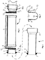
- FIG. 1 is the longitudinal section of a stainless steel tube 1 shown.
- On the other side is a folded web 7 for Pipe stiffening trained.
- a nut 3 fixed to the stainless steel tube 1 fastens the screw 3 '(see. Fig. 2, right), which on Elongated hole 4 for the non-rotating connection of the Stainless steel tubes 1 is inserted one below the other.
- the elongated hole 4 allows an additional through this axial play connection low mobility of the stainless steel tubes 1 with each other.
- the installation length of the stainless steel tube 1 is approximately 70 cm, the elongated hole 4 is about 5 cm long so that a Axial play of a few centimeters results.
- connection parts 6a and 6b designed for the stainless steel tubes 1, which are drawn from the main part (see also the double arrow to Fig. 1) are shifted.
- the connecting part 6a is analogous to the corresponding end of a stainless steel tube 1 with web 7, Nut 3 and wedge seal 2 equipped.
- the connecting part 6b has an elongated hole 4 for the Screw 3 'and additionally a sliding wedge seal 8 on End plate 12 on.
- a swelling band 9 on the two Connection parts 6a and 6b and on the outer wall 10 of the Stainless steel channel 5 prevents groundwater from rising.
- the installation length of this stainless steel narrow part 5 is approximately 90 cm.
- FIG. 3 is the cross section of a stainless steel channel part 1 shown.
- the drain of the wastewater is an upper opening 14 as a revision option educated.
- At the side tabs 11 Fixed to the inspection shaft floor with dowels 15.
- Upper webs 16 with an inclination of approx. 10 ° inwards serve for example, to return splashed water to the inside.
Landscapes
- Engineering & Computer Science (AREA)
- General Engineering & Computer Science (AREA)
- Health & Medical Sciences (AREA)
- Life Sciences & Earth Sciences (AREA)
- Hydrology & Water Resources (AREA)
- Public Health (AREA)
- Water Supply & Treatment (AREA)
- Mechanical Engineering (AREA)
- Rigid Pipes And Flexible Pipes (AREA)
- Turning (AREA)
- Sewage (AREA)
Applications Claiming Priority (2)
| Application Number | Priority Date | Filing Date | Title |
|---|---|---|---|
| DE20112746U DE20112746U1 (de) | 2001-08-04 | 2001-08-04 | Rohrreliningvorrichtung |
| DE20112746U | 2001-08-04 |
Publications (2)
| Publication Number | Publication Date |
|---|---|
| EP1281910A2 true EP1281910A2 (fr) | 2003-02-05 |
| EP1281910A3 EP1281910A3 (fr) | 2004-03-10 |
Family
ID=7960026
Family Applications (1)
| Application Number | Title | Priority Date | Filing Date |
|---|---|---|---|
| EP02017468A Withdrawn EP1281910A3 (fr) | 2001-08-04 | 2002-08-05 | Arrangement de chemisage pour tuyaux |
Country Status (2)
| Country | Link |
|---|---|
| EP (1) | EP1281910A3 (fr) |
| DE (1) | DE20112746U1 (fr) |
Cited By (1)
| Publication number | Priority date | Publication date | Assignee | Title |
|---|---|---|---|---|
| EP1533560A1 (fr) * | 2003-11-19 | 2005-05-25 | Uponor Innovation Ab | Procédé de regarnissage des canalisations enterrées |
Family Cites Families (7)
| Publication number | Priority date | Publication date | Assignee | Title |
|---|---|---|---|---|
| DE3418605A1 (de) * | 1984-05-18 | 1985-11-21 | Paul 6200 Wiesbaden Heidenreich | Kanalsohlen-innenschale |
| DE3728192A1 (de) * | 1987-08-24 | 1989-03-09 | Muecher Hermann Gmbh | Innenflaechenschutz fuer eine rohrleitung |
| DE4122299C2 (de) * | 1991-07-05 | 1996-05-23 | Bernhard Kessel | Schacht |
| DE9315666U1 (de) * | 1993-04-30 | 1993-12-16 | Gelsenwasser AG, 45891 Gelsenkirchen | Vorrichtung zum Verlegen unterirdischer Rohrleitungen |
| DE4439597C2 (de) * | 1994-11-05 | 1998-02-26 | Uhrig Kanaltechnik Gmbh | Verfahren zur Reparatur von Schadstellen unterirdischer Abwasserkanäle |
| US5662432A (en) * | 1995-03-27 | 1997-09-02 | Cook Construction Company, Inc. | Pipe insertion machine and method |
| DE19608352C1 (de) * | 1996-03-05 | 1997-07-24 | Fitr Ges Fuer Innovation Im Ti | Rohrleitung zur Sanierung einer druck- und temperaturbelasteten Rohrleitung und Verfahren und Vorrichtung zum Einbringen in die geschädigte Rohrleitung |
-
2001
- 2001-08-04 DE DE20112746U patent/DE20112746U1/de not_active Expired - Lifetime
-
2002
- 2002-08-05 EP EP02017468A patent/EP1281910A3/fr not_active Withdrawn
Cited By (1)
| Publication number | Priority date | Publication date | Assignee | Title |
|---|---|---|---|---|
| EP1533560A1 (fr) * | 2003-11-19 | 2005-05-25 | Uponor Innovation Ab | Procédé de regarnissage des canalisations enterrées |
Also Published As
| Publication number | Publication date |
|---|---|
| DE20112746U1 (de) | 2002-09-12 |
| EP1281910A3 (fr) | 2004-03-10 |
Similar Documents
| Publication | Publication Date | Title |
|---|---|---|
| DE69003672T2 (de) | Verfahren zur Sanierung und/oder zum Schutz von Abwasserkanälen oder Rohrleitungen. | |
| CH681905A5 (fr) | ||
| EP1312848B1 (fr) | Raccord de tuyaux et procédé pour atteindre un raccord de tuyaux | |
| EP1375114A2 (fr) | Procédé pour la connection d'un premier et second tube en matière synthétique et tube | |
| EP0457319B1 (fr) | Manchon d'étanchéité et son application | |
| DE3814913C2 (fr) | ||
| DE202004005768U1 (de) | Bauteil bzw. Bauwerk zur Leitung von Wasser, das im Gerinne mit einer Wärmerückgewinnung ausgestattet werden kann | |
| DE102008058042B4 (de) | Rohrkupplung für Rohre | |
| EP1281910A2 (fr) | Arrangement de chemisage pour tuyaux | |
| DE102008040004A1 (de) | Rohr und Verfahren für die Abwasserwärmenutzung | |
| EP1271728A1 (fr) | Revêtement interne pour fixer des câbles dans un tuyau d'égout | |
| WO2008122403A1 (fr) | Système de forage | |
| CH684546A5 (de) | Rohr zum Rohr-in-Rohr-Sanieren von Rohrleitungen sowie Verfahren zum Einbauen dieses Rohres und Vorrichtung zur Ausführung des Verfahrens. | |
| EP1591712B1 (fr) | Tuyau de connection et sa application | |
| DE102020134023B4 (de) | Manschettenanschlussvorrichtung, Herstellungsverfahren und Verfahren zur Einbindung oder Sanierung von Anschlüssen | |
| DE69806808T2 (de) | Vorrichtung zum dichten verbinden von rohren für den transport von flüssigkeiten | |
| DE102010045241A1 (de) | Abwasserschacht | |
| DE102009053319A1 (de) | Anordnung zum Sanieren schadhafter Rohrleitungen eines Kanalnetzes | |
| DE2854224A1 (de) | Verfahren zum ausbessern von im erdreich verlegten rohrleitungen oder kanaelen und vorrichtung zur durchfuehrung des verfahrens | |
| DE102004032397A1 (de) | Schachtanschlussmuffe | |
| WO2025252978A1 (fr) | Attache de fixation pour bouchons de douille | |
| DE202006001226U1 (de) | Anschlussstutzen für einen Abwasser-Hauptkanal | |
| EP0859094A1 (fr) | Système de puits d'accès et moyen d'introduction | |
| EP0436060A1 (fr) | Procédé de gainage d'enceintes, notamment pour la restauration des conduites endommagées | |
| DE102010011868A1 (de) | Abwasserschacht |
Legal Events
| Date | Code | Title | Description |
|---|---|---|---|
| PUAI | Public reference made under article 153(3) epc to a published international application that has entered the european phase |
Free format text: ORIGINAL CODE: 0009012 |
|
| AK | Designated contracting states |
Designated state(s): AT BE BG CH CY CZ DE DK EE ES FI FR GB GR IE IT LI LU MC NL PT SE SK TR |
|
| AX | Request for extension of the european patent |
Extension state: AL LT LV MK RO SI |
|
| PUAL | Search report despatched |
Free format text: ORIGINAL CODE: 0009013 |
|
| AK | Designated contracting states |
Kind code of ref document: A3 Designated state(s): AT BE BG CH CY CZ DE DK EE ES FI FR GB GR IE IT LI LU MC NL PT SE SK TR |
|
| AX | Request for extension of the european patent |
Extension state: AL LT LV MK RO SI |
|
| RIC1 | Information provided on ipc code assigned before grant |
Ipc: 7E 03F 3/06 B Ipc: 7F 16L 21/035 B Ipc: 7F 16L 55/165 A |
|
| 17P | Request for examination filed |
Effective date: 20040908 |
|
| AKX | Designation fees paid |
Designated state(s): AT BE BG CH CY CZ DE DK EE ES FI FR GB GR IE IT LI LU MC NL PT SE SK TR |
|
| 17Q | First examination report despatched |
Effective date: 20050414 |
|
| GRAP | Despatch of communication of intention to grant a patent |
Free format text: ORIGINAL CODE: EPIDOSNIGR1 |
|
| STAA | Information on the status of an ep patent application or granted ep patent |
Free format text: STATUS: THE APPLICATION IS DEEMED TO BE WITHDRAWN |
|
| 18D | Application deemed to be withdrawn |
Effective date: 20060926 |