EP1281982A2 - Method for the evaluation of the coherency of acoustic waves - Google Patents
Method for the evaluation of the coherency of acoustic waves Download PDFInfo
- Publication number
- EP1281982A2 EP1281982A2 EP02012275A EP02012275A EP1281982A2 EP 1281982 A2 EP1281982 A2 EP 1281982A2 EP 02012275 A EP02012275 A EP 02012275A EP 02012275 A EP02012275 A EP 02012275A EP 1281982 A2 EP1281982 A2 EP 1281982A2
- Authority
- EP
- European Patent Office
- Prior art keywords
- electroacoustic
- evaluation factor
- output signals
- amount
- distance
- Prior art date
- Legal status (The legal status is an assumption and is not a legal conclusion. Google has not performed a legal analysis and makes no representation as to the accuracy of the status listed.)
- Granted
Links
Images

Classifications
-
- G—PHYSICS
- G01—MEASURING; TESTING
- G01S—RADIO DIRECTION-FINDING; RADIO NAVIGATION; DETERMINING DISTANCE OR VELOCITY BY USE OF RADIO WAVES; LOCATING OR PRESENCE-DETECTING BY USE OF THE REFLECTION OR RERADIATION OF RADIO WAVES; ANALOGOUS ARRANGEMENTS USING OTHER WAVES
- G01S3/00—Direction-finders for determining the direction from which infrasonic, sonic, ultrasonic or electromagnetic waves, or particle emission, not having a directional significance, are being received
- G01S3/80—Direction-finders for determining the direction from which infrasonic, sonic, ultrasonic or electromagnetic waves, or particle emission, not having a directional significance, are being received using ultrasonic, sonic or infrasonic waves
- G01S3/802—Systems for determining direction or deviation from predetermined direction
- G01S3/808—Systems for determining direction or deviation from predetermined direction using transducers spaced apart and measuring phase or time difference between signals therefrom, i.e. path-difference systems
- G01S3/8083—Systems for determining direction or deviation from predetermined direction using transducers spaced apart and measuring phase or time difference between signals therefrom, i.e. path-difference systems determining direction of source
-
- G—PHYSICS
- G01—MEASURING; TESTING
- G01S—RADIO DIRECTION-FINDING; RADIO NAVIGATION; DETERMINING DISTANCE OR VELOCITY BY USE OF RADIO WAVES; LOCATING OR PRESENCE-DETECTING BY USE OF THE REFLECTION OR RERADIATION OF RADIO WAVES; ANALOGOUS ARRANGEMENTS USING OTHER WAVES
- G01S3/00—Direction-finders for determining the direction from which infrasonic, sonic, ultrasonic or electromagnetic waves, or particle emission, not having a directional significance, are being received
- G01S3/80—Direction-finders for determining the direction from which infrasonic, sonic, ultrasonic or electromagnetic waves, or particle emission, not having a directional significance, are being received using ultrasonic, sonic or infrasonic waves
- G01S3/801—Details
Definitions
- the invention relates to a method for evaluating the Coherence of sound waves that are spatial extensive reception base with several, from each other spaced, electroacoustic receiver of a sonar system spread.
- a reception base is used with three electroacoustic transducers which are arranged on a straight line and are at a distance from one another which is a multiple of the wavelength of that from the sound source radiated sound.
- the electrical output signals of the middle transducer are cross-correlated with the output signals of each outer transducer and so the time shift between the output signals of the transducers is determined.
- the invention has for its object a method to indicate with which with little Signal processing effort the coherence of one Base of reception of a sonar system received sound waves specify and thus have the quality of the measurement results checked.
- the inventive method with the features of Claim 1 has the advantage that it is low Additional effort parallel to known methods of detection, Location and classification of sound radiating targets can be applied and existing hardware and Software components of the sonar system can be used.
- the method according to the invention enables the of the measurement results supplied by the measurement method and gives the User with which confidence measure he of the Reliability of the measured, current sonar data can, so that he uses a quality assessment of a Multitude of measured sonar data much faster the with high probability correct sonar data filter out and then an early decision can support.
- the two standardized complex signals in a time window is scanned at the same times and the two belonging to the same time Samples added. From the resulting sum, the Amount formed. Then the amounts of the sums are added and an average is formed from the addition result and output as an evaluation factor.
- the calculation algorithm does not directly calculate the amounts of the sums or of the differences added and averaged and then the Subtracted mean values, but after forming the amount of Sum and the amount of the difference of two each Samples already the amount of the difference from the amount of the sums subtracted and the addition and averaging applied to the subtraction results thus obtained.
- the complex signal using a Hilbert transform generated and its normalization by dividing the complex Signal made by its amount.
- the Hilbert transformation and normalization can be anywhere in the signal processing of the output signals, so that existing hardware and software components for a existing measuring method for measuring sonar data optimally to implement the method according to the invention minimal additional effort can be used.
- Digitization of the output signals in the signal processing path can the Hilbert transformation on the digital records of the output signals are applied and through FIR filter structures respectively.
- electroacoustic transducers with dipole or All-round characteristics can be used. Also groups of electroacoustic transducers operating in horizontal or are arranged at a distance from each other in the vertical direction, can serve as recipients. That of the invention Signal processing subjected to electrical output signal of the The preprocessed group signal is then the receiver Converter group.
- the inventive method in connection with a Process for the passive location of a water Sound source using three linearly spaced apart arranged, electroacoustic transducers, the so-called PRS process, used by using the middle converter and a selected pair of each outer transducer electroacoustic receivers is formed and from the like described evaluation factors the time or Phase shifts between the middle converter and the both outer transducers determined and in a known manner Calculation of bearing angle and distance of the sound source be used.
- a spatially extensive reception base with several electro-acoustic receivers spaced apart from one another is used in sonar technology.
- This reception base 10 has three receivers, each of which is formed by an electroacoustic transducer 11.
- the three transducers 11 are arranged exactly on a straight line at a distance L from one another.
- the middle converter 11-2 is arranged amidships near the tower and the two outer converters 11-1 and 11-2 are arranged near the stern and the bow.
- the phase or time shifts between the electrical output signals of the middle transducer 11-2 and each of the outer transducers 11-1 and 11-3 are determined and from this the bearing angle ⁇ 0 and the distance R 0 according to Eq. (1) and (2) calculated.
- the usually amplified and digitized output signals of the converters 11-1 and 11-2 on the one hand and 11-2 and 11-3 on the other hand are each fed to a cross correlator 12 and 13, respectively, which has the time shift ⁇ 1,2 and ⁇ 2,3 between the output signals determined.
- the information quality of the location procedure will increase Coherence of the and sound wave received by the transducers 11.
- the the evaluation factor gained is an indication that with what probability the accuracy of the sonar data can be assumed.
- To gain this Evaluation factor is in the reception base 10 with the three Transducers 11 selected at least one pair of transducers and the Coherence of the phases of the electrical output signals of the determined two selected transducers 11.
- a complex signal c j (t) that can be written is generated from each output signal of the converter pair, which represents a real signal s j (t) by means of a Hilbert transform H (s j (t))
- a j (t) ⁇ exp [i ⁇ ⁇ j (t)] represents an analytical description of the signal.
- a j (t) describes the envelope of s j (t) and ⁇ j (t) the current phase.
- the amount of the difference is subtracted from the amount of the sum and the addition and the averaging are applied to the subtraction results obtained in this way, so that after subtracting the amount of the sum and the amount of the difference from two mutually associated samples for the calculation of the phase coherence C * ( ⁇ ) the following equation is obtained:
- the formation of the complex analytical signals c j (t) by means of the Hilbert transform H (s j (t)) and the subsequent normalization can be inserted at any point in the direct processing path of the (real) output signals of the two receivers.
- the Hilbert transformation is applied to the digital samples of the scanning signals, the digital samples being used as samples of the time window.
- each electrical output signal of the selected pair of electroacoustic receivers which in accordance with the exemplary embodiment in FIG. 3 are formed by two transducers 11 of the reception base 10, is amplified, sampled and digitized.
- an amplifier 15 and a sampling unit 16 sample and hold
- an analog-digital converter 17 are provided.
- the A / D converter 17 is dispensed with.
- the sampling unit 16 samples the amplified output signal at fixed time intervals ⁇ t and the digitized data sets of the samples or samples are fed to a Hilbert transformer 18, at the outputs of which both the real and the imaginary part of the complex analytical signal c j (t) are taken can.
- the real and imaginary parts are fed separately on the one hand to an amount generator 19 and on the other hand to a divider 20 or 21, the other input of which is connected to the output of the amount generator 19.
- the normalized real part and the normalized imaginary part are reassembled in the adder 22 to the sample of the normalized, complex signal p j (t).
- the two standardized complex signals p 1 (t) and p 2 (t) thus result for the electrical output signals of the two converters 11 of the selected converter pair processed in the manner described.
- the components of the circuit arrangement specified in FIG. 2 are used to calculate the G1. (6) specified above.
- the samples or samples of the two standardized complex signals p 1 (t) and p 2 (t) are supplied on the one hand to an adder 23 and on the other hand to a subtractor 24.
- the sum of the sum of two samples belonging to the same sampling time and the difference of these samples output at the output of the subtractor 24 is output in the amount formers 25 and 26, and the two amounts of sum and difference become a subtractor 27 fed, which subtracts the amount of the difference from the amount of the sum.
- the subtraction results of the N samples are added in the summer 29, and in the divider 30 the addition result is divided by the number 2N of the samples delivered in total from both signals p j (t).
- the evaluation factor for the phase coherence of the two output signals which can be removed at the output of the divider 30, assumes the value +1 if both signals are exactly correlated and the value -1 if both signals are completely anti-correlated. An intermediate value indicates a lower degree of agreement between the two signals.
- the evaluation factor C * ( ⁇ ) thus determined for the coherence of a received sound wave is used in the sonar system described with FIG. 3 for locating a sound source for evaluating the measurement results for the bearing angle and distance of the sound source output by the sonar system.
- a transducer pair is selected in the reception base 10 of the sonar system consisting of three electroacoustic transducers 11, in the exemplary embodiment in FIG. 3 the transducer pair from the two outer transducers 11-1 and 11-3.
- the electrical output signals of the two outer transducers are subjected to signal processing as described above, blocks 31 and 32 corresponding to the part of the circuit arrangement shown in FIG. 1 and block 34 to the part of the circuit arrangement shown in FIG. 2.
- the sonar data are shown as false values if the evaluation factor C * ( ⁇ 1.3 ) is below a default value, for example 0.5.
- the evaluation factor C * ( ⁇ 1.3 ) is fed to the computer 14 via a corresponding threshold 35, so that the computer 14 only calculates the sonar data ⁇ 0 , R 0 if C * ( ⁇ 1.3 ) the threshold 35 exceeds.
- the output evaluation factor C * ( ⁇ 1.3 ) can also be assigned as a confidence measure to the calculated sonar data ⁇ 0 , R 0 , so that the user can carry out an evaluation of the measured sonar data based on the assigned confidence measures.
- each converter 11 is assigned a block 31, 32, 33 in which signal processing is carried out, as has been described for FIGS. 1 and 2.
- block 31 the normalized complex signal p 1 (t) in block 32, the normalized complex signal p 2 (t) and in the block 33, the normalized complex signal p 3 (t) is generated.
- the signal p 1 (t) is fed to the block 35, the signal p 3 (t) to the block 36 and the signal p 2 (t) to both the block 35 and the block 36.
- Each block 35 and 36 corresponds to the phase correlator, the circuit of which is indicated in FIG. 2.
- Block 35 provides the evaluation factor C * ( ⁇ 1,2 ), which is dependent on the time shift between the output signals of the converters 11-1 and 11-2, and block 36 supplies the evaluation factor C * ( ⁇ 2,3 ), which is a function of the time shift between the signals from transducers 11-2 and 11-3.
- Each block 35, 36 is followed by a calibration stage 38 or 39. In the Kalibirier tone 38 of the factor C * ( ⁇ 1.2) as a function of time shift ( ⁇ 1.2) are stored.
- the receivers of the reception base 10 can of individual transducers 11, which are a dipole or Have all-round characteristics, are formed.
- electroacoustic receivers of the reception base 10 can groups of electroacoustic transducers 11 are also used be in the horizontal direction or in the vertical direction are linearly spaced from each other. In case of vertical arrangement is called Staves. In such Cases will be processed as described Output signal of the receiver on from the output signals group signal derived from the converter groups.
- the method according to the invention can also be used to the linear alignment of the in a so-called trailing antenna arranged electro-acoustic transducers to evaluate.
- the evaluation factor allows conclusions to be drawn about the offset of a transducer with respect to the linear alignment.
Landscapes
- Physics & Mathematics (AREA)
- Engineering & Computer Science (AREA)
- General Physics & Mathematics (AREA)
- Radar, Positioning & Navigation (AREA)
- Remote Sensing (AREA)
- Measurement Of Velocity Or Position Using Acoustic Or Ultrasonic Waves (AREA)
Abstract
Description
Die Erfindung betrifft ein Verfahren zur Bewertung der Kohärenz von Schallwellen, die sich über eine räumlich ausgedehnte Empfangsbasis mit mehreren, voneinander beabstandeten, elektroakustischen Empfänger einer Sonaranlage ausbreiten.The invention relates to a method for evaluating the Coherence of sound waves that are spatial extensive reception base with several, from each other spaced, electroacoustic receiver of a sonar system spread.
Bei der Detektion, Ortung und Klassifikation von Schallquellen, die Schall ins Wasser abstrahlen, von einem weit entfernten Standort aus spielt die Kohärenz der am Standort von der Empfangsbasis der Sonaranlage empfangenen Schallwellen eine wesentliche Rolle für die Genauigkeit und Zuverlässigkeit der Meßergebnisse. Die Konfidenz der Meßergebnisse hängt damit von der Kenntnis des Maßes ab, mit dem ein an einem bestimmten Empfänger der Empfangsbasis empfangenes Signal der gleichen Schallquelle zugehörig ist.In the detection, location and classification of Sound sources that emit sound into the water from one far away location plays the coherence of the am Location received from the receiving base of the sonar system Sound waves play an essential role in accuracy and Reliability of the measurement results. The confidence of the Measurement results thus depends on the knowledge of the dimension with the one at a specific recipient of the reception base received signal belongs to the same sound source.
Bei einem bekannten Verfahren zur Bestimmung des Ortes einer
Schallquelle nach Peilung und Entfernung (US 4 910 719) wird
eine Empfangsbasis mit drei elektroakustischen Wandlern
verwendet, die auf einer Geraden angeordnet sind und einen
Abstand voneinander aufweisen, der ein Vielfaches der
Wellenlänge des von der Schallquelle abgestrahlten Schalls
beträgt. Die elektrischen Ausgangssignale des mittleren
Wandlers werden mit den Ausgangssignalen eines jeden äußeren
Wandlers kreuzkorreliert und so die Zeitverschiebung zwischen
den Ausgangssignalen der Wandler bestimmt. Mit den gemessenen
Zeitverschiebungen τ1,2 und τ2,3 werden in bekannter Weise der
Peilwinkel 0 zur Schallquelle gemäß
Diese Meßergebnisse sind nur dann zuverlässig, wenn sichergestellt ist, daß die Empfangssignale der drei Wandler miteinander vollständig oder weitgehend korrelieren, d.h. von der gleichen Schallquelle herrühren. Ist dagegen der Schallempfang durch stochastische Störquellen oder Inhomogimitäten des Ausbreitungsmediums, wie z.B. Schlieren, Lufteinschlüsse, Schichtungen, gestört, so sind die Ausgangssignale der Wandler nicht mehr kohärent, und die wie vorstehend berechneten Peilwinkel- und Entfernungswerte stellen unbrauchbare Meßergebnisse dar.These measurement results are only reliable if it is ensured that the received signals of the three converters fully or largely correlate with each other, i.e. of come from the same sound source. But is that Sound reception through stochastic sources of interference or Inhomogimities of the propagation medium, e.g. Schlieren, Air pockets, stratifications, disturbed, that's what they are Output signals from the converters are no longer coherent, and the how bearing angle and distance values calculated above represent useless measurement results.
Der Erfindung liegt die Aufgabe zugrunde, ein Verfahren anzugeben, mit dem sich mit geringem Signalverarbeitungsaufwand die Kohärenz der von einer Empfangsbasis einer Sonaranlage empfangenen Schallwellen angeben und damit die Qualität der Meßergebnisse prüfen läßt. The invention has for its object a method to indicate with which with little Signal processing effort the coherence of one Base of reception of a sonar system received sound waves specify and thus have the quality of the measurement results checked.
Die Aufgabe ist erfindungsgemäß durch die Merkmale im
Anspruch 1 gelöst.The object is according to the features in
Das erfindungsgemäße Verfahren mit den Merkmalen des
Anspruchs 1 hat den Vorteil, daß es mit geringem
Zusatzaufwand parallel zu bekannten Verfahren der Detektion,
Ortung und Klassifikation von schallabstrahlenden Zielen
angewendet werden kann und dabei ohnehin vorhandene Hard- und
Softwarekomponenten der Sonaranlage genutzt werden können.
Das erfindungsgemäße Verfahren ermöglicht eine Kontrolle der
von den Meßverfahren gelieferten Meßergebnisse und gibt dem
Nutzer an, mit welchem Konfidenzmaß er von der
Zuverlässigkeit der gemessenen, aktuellen Sonardaten ausgehen
kann, so daß er mittels einer Qualitätsbewertung einer
Vielzahl von gemessenen Sonardaten sehr viel schneller die
mit hoher Wahrscheinlichkeit richtigen Sonardaten
herausfiltern und darauf eine frühzeitige Entscheidung
stützen kann.The inventive method with the features of
Zweckmäßige Ausführungsformen des erfindungsgemäßen Verfahrens mit vorteilhaften Weiterbildungen und Ausgestaltungen der Erfindung ergeben sich aus den weiteren Ansprüchen.Appropriate embodiments of the invention Process with advantageous developments and Refinements of the invention result from the others Claims.
Gemäß einer bevorzugten Ausführungsform der Erfindung wird zur Bestimmung der Phasenkohärenz aus jedem Ausgangssignal der beiden ausgewählten Empfänger ein normiertes, komplexes Signal gebildet, die beiden normierten komplexen Signale in einem Zeitfenster zu gleichen Zeitpunkten abgetastet und jeweils die den gleichen Zeitpunkten zugehörigen beiden Abtastwerte addiert. Von der sich ergebenden Summe wird der Betrag gebildet. Dann werden die Beträge der Summen addiert und von dem Additionsergebnis wird ein Mittelwert gebildet und als Bewertungsfaktor ausgegeben. Die Mittelwertbildung, die sich aus der Division des Additionsergebnisses durch die Anzahl der Abtastwerte in beiden normierten, komplexen Signalen ergibt, stellt sicher, daß bei vollständiger Korrelation, d.h. exakter Übereinstimmung beider Signale, der Bewertungsfaktor C = 1 ist. Bei vollständiger Antikorrelation, d.h. wenn die Signale zwar kohärent aber um 180° phasenverschoben sind, ergibt sich der Bewertungsfaktor C = 0.According to a preferred embodiment of the invention to determine the phase coherence from each output signal a standardized, complex of the two selected receivers Signal formed, the two standardized complex signals in a time window is scanned at the same times and the two belonging to the same time Samples added. From the resulting sum, the Amount formed. Then the amounts of the sums are added and an average is formed from the addition result and output as an evaluation factor. The averaging, which results from dividing the addition result by the Number of samples in both standardized, complex Signals, ensures that when complete Correlation, i.e. exact match of both signals, the Evaluation factor C = 1. With complete Anti-correlation, i.e. if the signals are coherent but around Are 180 ° out of phase, the evaluation factor results C = 0.
Gemäß einer vorteilhaften Ausführungsform der Erfindung werden zusätzlich jeweils die den gleichen Zeitpunkten zugehörigen Abtastwerte voneinander subtrahiert und wird von der Differenz der Betrag gebildet. Die Beträge der Differenzen werden addiert, von dem Additionsergebnis wird ein zweiter Mittelwert gebildet und der zweite Mittelwert wird von dem wie vorstehend beschrieben erhaltenen ersten Mittelwert subtrahiert. Die Differenz der beiden Mittelwerte wird als modifizierter Bewertungfaktor C* ausgegeben. Durch diese zusätzlichen Verfahrensschritte zur Berechnung des modifizierten Bewertungsfaktors C* sind die Grenzwerte des Bewertungsfaktors C* für vollständige Korrelation und vollständige Antikorrelation nicht mehr - wie vorstehend - auf 1 und 0, sondern jetzt auf 1 bzw. -1 festgelegt. Ist die Korrelation zwischen den Ausgangssignalen gestört, ergeben sich betragsmäßig kleinere Werte.According to an advantageous embodiment of the invention will also be the same times associated samples are subtracted from each other and is derived from the difference the amount formed. The amounts of Differences are added from the addition result a second mean is formed and the second mean is obtained from the first obtained as described above Subtracted mean. The difference between the two means is output as a modified evaluation factor C *. By these additional process steps to calculate the modified weighting factor C * are the limit values of the Weighting factor C * for complete correlation and complete anti-correlation no longer - as above - to 1 and 0, but now set to 1 and -1 respectively. Is the Correlation between the output signals disturbed smaller amounts.
Zur Vereinfachung des vorstehend beschriebenen Rechenalgorithmus werden nicht direkt die Beträge der Summen bzw. der Differenzen addiert und gemittelt und dann die Mittelwerte subtrahiert, sondern nach Bildung des Betrags der Summe und des Betrags der Differenz von jeweils zwei Abtastwerten bereits der Betrag der Differenz von dem Betrag der Summen subtrahiert und die Addition und Mittelwertbildung auf die so erhaltenen Subtraktionsergebnisse angewandt.To simplify the above The calculation algorithm does not directly calculate the amounts of the sums or of the differences added and averaged and then the Subtracted mean values, but after forming the amount of Sum and the amount of the difference of two each Samples already the amount of the difference from the amount of the sums subtracted and the addition and averaging applied to the subtraction results thus obtained.
Gemäß einer vorteilhaften Ausführungsform der Erfindung wird das komplexe Signal mittels einer Hilbert-Transformierten erzeugt und dessen Normierung durch Division des komplexen Signals durch seinen Betrag vorgenommen. Die Hilbert-Transformation und die Normierung kann an beliebiger Stelle in der Signalverarbeitung der Ausgangssignale erfolgen, so daß vorhandene Hard- und Softwarekomponenten für ein vorhandenes Meßverfahren zur Messung von Sonardaten optimal zur Realisierung des erfindungsgemäßen Verfahrens bei minimalem Zusatzaufwand genutzt werden können. Bei früher Digitalisierung der Ausgangssignale im Signalverarbeitungsweg kann die Hilbert-Transformation auf die digitalen Datensätze der Ausgangssignale angewendet werden und durch FIR-Filterstrukturen erfolgen.According to an advantageous embodiment of the invention the complex signal using a Hilbert transform generated and its normalization by dividing the complex Signal made by its amount. The Hilbert transformation and normalization can be anywhere in the signal processing of the output signals, so that existing hardware and software components for a existing measuring method for measuring sonar data optimally to implement the method according to the invention minimal additional effort can be used. In the past Digitization of the output signals in the signal processing path can the Hilbert transformation on the digital records of the output signals are applied and through FIR filter structures respectively.
Als elektroakustische Empfänger können einzelne elektroakustische Wandler mit Dipol- oder Rundumcharakteristik verwendet werden. Auch Gruppen von elektroakustischen Wandlern, die in horizontaler oder vertikaler Richtung voneinander beabstandet angeordnet sind, können als Empfänger dienen. Das der erfindungsgemäße Signalverarbeitung unterzogene elektrische Ausgangssignal des Empfängers ist dann das vorverarbeitete Gruppensignal der Wandlergruppe.Individuals can be used as electroacoustic receivers electroacoustic transducers with dipole or All-round characteristics can be used. Also groups of electroacoustic transducers operating in horizontal or are arranged at a distance from each other in the vertical direction, can serve as recipients. That of the invention Signal processing subjected to electrical output signal of the The preprocessed group signal is then the receiver Converter group.
Obwohl die Bedeutung des erfindungsgemäßen Verfahrens in der Kontrolle herkömmlicher Detektions-, Ortungs- und Klassifizierungsverfahren, z.B. PRS (Passiv Ranging Sonar) oder Transientendetektion (vgl. Naval Forces No. VI/1987, Seite 27 - 30) liegt, ist es möglich, das Verfahren selbst zur direkten Detektion und Ortung einzusetzen. Hierzu wird z.B. gemäß einer vorteilhaften Ausführungsform der Erfindung das erfindungsgemäße Verfahren in Verbindung mit einem Verfahren zum passiven Orten einer im Wasser befindlichen Schallquelle mittels dreier im Abstand voneinander linear angeordneten, elektroakustischen Wandlern, dem sog. PRS-Verfahren, verwendet, indem mit dem mittleren Wandler und jedem äußeren Wandler jeweils ein ausgewähltes Paar von elektroakustischen Empfängern gebildet wird und aus den wie beschrieben ermittelten Bewertungsfaktoren die Zeit- oder Phasenverschiebungen zwischen dem mittleren Wandler und den beiden äußeren Wandlern bestimmt und in bekannter Weise zur Berechnung von Peilwinkel und Entfernung der Schallquelle verwendet werden.Although the importance of the inventive method in the Control of conventional detection, location and Classification procedures, e.g. PRS (Passive Ranging Sonar) or transient detection (see Naval Forces No. VI / 1987, Pages 27-30), it is possible to do the procedure yourself for direct detection and location. This will e.g. according to an advantageous embodiment of the invention the inventive method in connection with a Process for the passive location of a water Sound source using three linearly spaced apart arranged, electroacoustic transducers, the so-called PRS process, used by using the middle converter and a selected pair of each outer transducer electroacoustic receivers is formed and from the like described evaluation factors the time or Phase shifts between the middle converter and the both outer transducers determined and in a known manner Calculation of bearing angle and distance of the sound source be used.
Die Erfindung ist anhand eines in der Zeichnung illustrierten Ausführungsbeispiels im folgenden näher beschrieben. Es zeigen
- Fig. 1 und 2
- ein Blockschaltbild einer Schaltungsanordnung für ein Verfahren zur Bewertung der Kohärenz von Schallwellen, wobei in Fig. 1 der Schaltungsteil zur komplexen Signalanalyse und in Fig. 2 der Schaltungsteil zur Phasenkorrelation dargestellt ist,
- Fig. 3
- ein Blockschaltbild einer PRS-Anlage in Verbindung mit der Schaltungsanordnung in Fig. 1 und 2,
- Fig. 4
- ein Blockschaltbild einer erweiterten Schaltungsanordnung gemäß Fig. 1 und 2 zur Ortung von Schallquellen.
- 1 and 2
- 3 shows a block diagram of a circuit arrangement for a method for evaluating the coherence of sound waves, the circuit part for complex signal analysis being shown in FIG. 1 and the circuit part for phase correlation being shown in FIG. 2,
- Fig. 3
- 2 shows a block diagram of a PRS system in connection with the circuit arrangement in FIGS. 1 and 2,
- Fig. 4
- a block diagram of an extended circuit arrangement according to FIGS. 1 and 2 for locating sound sources.
Zur Detektion, Ortung und Klassifikation von Schallquellen,
die Schall ins Wasser abstrahlen, wird in der Sonartechnik
eine weit von der Schallquelle entfernte, räumlich
ausgedehnte Empfangsbasis mit mehreren voneinander
beabstandeten, elektroakustischen Empfängern verwendet. In
Fig. 3 und 4 ist ein Ausführungsbeispiel einer Sonaranlage
zur Ortung von Schallquellen durch Bestimmen des Peilwinkels
und der Entfernung im Blockschaltbild dargestellt. Diese
Empfangsbasis 10 hat drei Empfänger, die jeweils von einem
elektroakustischen Wandler 11 gebildet werden. Die drei
Wandler 11 sind im Abstand L voneinander exakt auf einer
Geraden angeordnet. Bei der Installation einer solchen
Empfangsbasis an einem U-Boot ist der mittlere Wandler 11-2
mittschiffs in Turmnähe und die beiden äußeren Wandler 11-1
und 11-2 nahe des Hecks und des Bugs angeordnet. Für die
Ortung einer Schallquelle werden die Phasen- oder
Zeitverschiebungen zwischen den elektrischen Ausgangssignalen
des mittleren Wandlers 11-2 und jedem der äußeren Wandler
11-1 und 11-3 bestimmt und daraus der Peilwinkel 0 und die
Entfernung R0 gemäß den vorstehenden Gl. (1) und (2)
berechnet. Hierzu werden die üblicherweise verstärkten und
digitalisierten Ausgangssignale der Wandler 11-1 und 11-2
einerseits und 11-2 und 11-3 andererseits jeweils einem
Kreuzkorrelator 12 bzw. 13 zugeführt, der die
Zeitverschiebung τ1,2 bzw. τ2,3 zwischen den Ausgangssignalen
bestimmt. Diese Werte werden einem Rechner 14 zugeführt, der
aus diesen Werten, der bekannten Schallgeschwindigkeit im
Wasser und dem Wandlerabstand L den Peilwinkel 0, der gegen
die auf dem mittleren Wandler 11-2 aufgestellte Normale
gemessen ist, und die Entfernung R0 der Schallquelle zum
mittleren Wandler 11-2 gemäß den angegebenen Gl. (1) und (2)
berechnet. For the detection, location and classification of sound sources that emit sound into the water, a spatially extensive reception base with several electro-acoustic receivers spaced apart from one another is used in sonar technology. 3 and 4, an embodiment of a sonar system for locating sound sources by determining the bearing angle and the distance is shown in the block diagram. This
Um ein Konfidenzmaß für die so ermittelten Sonardaten,
Peilwinkel und Entfernungen, zu erhalten und damit die
Aussagequalität des Ortungsverfahrens zu steigern wird die
Kohärenz der über die Empfangsbasis 10 sich ausbreitenden und
von den Wandlern 11 empfangenen Schallwelle bewertet. Der
dabei gewonnen Bewertungsfaktor ist ein Indiz dafür, mit
welcher Wahrscheinlichkeit die Richtigkeit der Sonardaten
unterstellt werden kann. Zur Gewinnung dieses
Bewertungsfaktors wird in der Empfangsbasis 10 mit den drei
Wandlern 11 mindestens ein Wandlerpaar ausgewählt und die
Kohärenz der Phasen der elektrischen Ausgangssignale der
beiden ausgewählten Wandler 11 bestimmt.To provide a confidence measure for the sonar data so determined,
Bearing angles and distances, and thus the
The information quality of the location procedure will increase
Coherence of the and
sound wave received by the
Im einzelnen wird hierzu aus jedem Ausgangssignals des
Wandlerpaars, das ein reelles Signal sj(t) darstellt mittels
einer Hilbert-Transformierten H(sj(t)) ein komplexes Signal
cj(t) erzeugt, das sich schreiben läßt zu
Damit enthält das normierte komplexe Signal pj(t) mit j=1,2 nur noch die Phaseninformationen der Signale.The standardized complex signal p j (t) with j = 1.2 thus only contains the phase information of the signals.
Die beiden normierten komplexen Signale pj(t) mit j=1,2
werden in einem Zeitfenster t=t0 bis t=t0 + N • Δt in gleichen
Zeitintervallen Δt abgetastet und jeweils die den gleichen
Zeitpunkten zugehörigen beiden Abtastwerte addiert. Von der
Summe wird der Betrag gebildet. Die Beträge der Summen werden
addiert, und von dem Additionsergebnis wird der Mittelwert
gebildet, der als Bewertungsfaktor C ausgegeben wird. Diese
Berechnung der Phasenkohärenz der beiden zu vergleichende
Signale sj(t) mit j=1,2 läßt sich durch nachstehende
Gleichung beschreiben:

Die Mittelung des Additionsergebnisses stellt sicher, daß die Phasenkohärenz und damit der Bewertungsfaktor C(τ) im Falle exakter Übereinstimmung beider Ausgangssignale +1 wird. Im Falle einer vollständigen Antikorrelation wird C(τ)=0. Vollständige Antikorrelation bedeutet, daß die Signale kohärent sind, aber unterschiedliche Polarität besitzen, also zueinander um τ=180° oder T/2 verschoben sind, wenn T die Signalperiode ist. Die Abtastung der beiden Signale erfolgt in festen Zeitintervallen Δt, wobei n=1 der erste Abtastwert und n=N der letzte Abtastwert im Zeitfenster ist.The averaging of the addition result ensures that the Phase coherence and thus the evaluation factor C (τ) in the case exact match of both output signals +1. in the In the case of a complete anti-correlation, C (τ) = 0. Complete anti-correlation means that the signals are coherent, but have different polarities are shifted from each other by τ = 180 ° or T / 2 if T is the Signal period is. The two signals are sampled at fixed time intervals Δt, where n = 1 the first sample and n = N is the last sample in the time window.
Will man im Falle der vollständigen Antikorrelation einen Bewertungsfaktor von -1 erreichen, so müssen zusätzlich jeweils die den gleichen Zeitpunkten zugehörigen beiden Abtastwerte voneinander subtrahiert und muß von der Differenz der Betrag gebildet werden. Die Beträge der Differenzen werden dann addiert, und von dem Additionsergebnis ein zweiter Mittelwert gebildet, der von dem gemäß Gl. (5) gebildeten ersten Mittelwert abgezogen wird. Als Ergebnis erhält man einen modifizierten Bewertungsfaktor C* (τ), dessen Grenzen -1 und +1 betragen.If you want a complete anti-correlation one Must reach an evaluation factor of -1, so additionally the two belonging to the same time Samples are subtracted from each other and must be from the difference the amount to be formed. The amounts of the differences are then added, and one from the addition result second mean formed from that according to Eq. (5) first mean value formed is subtracted. As a result one obtains a modified evaluation factor C * (τ), the Limits are -1 and +1.
Zur Verringerung des Rechenaufwands werden vorteilhaft
bereits nach Bildung des Betrags der Summe und des Betrags
der Differenz von jeweils zwei einander zugehörigen
Abtastwerten der Betrag der Differenz von dem Betrag der
Summe subtrahiert und die Addition und die Mittelwertbildung
auf die so gewonnenen Subtraktionsergebnisse angewandt, so
daß man zur Berechnung der Phasenkohärenz C*(τ) nachstehende
Gleichung erhält:

Sind die beiden Signale perfekt korreliert, wird der zweite Term von Gl. (6) bei allen Abtastwerten 0 und der Bewertungsfaktor C*(τ) nimmt den Wert +1 an. Für den Fall von antikorrelierten Signalen wird der erste Term 0, während der zweite Term den Wert +2 annimmt, so daß der Bewertungsfaktor C*(τ) den Wert -1 erhält. Wenn keine Korrelation zwischen den Signalen besteht, dann werden beide Terme klein und ergeben einen betragsmäßig kleineren Wert. In den Gl. (5) und (6) ist τ die zwischen den beiden zu vergleichenden Signalen bestehende Zeitverschiebung. If the two signals are perfectly correlated, the second one Term from Eq. (6) for all samples 0 and Evaluation factor C * (τ) assumes the value +1. In the case of anticorrelated signals, the first term becomes 0, during the second term takes the value +2, so that the evaluation factor C * (τ) receives the value -1. If there is no correlation between the Signals, then both terms become small and result a smaller amount. In the Eq. (5) and (6) τ the signals to be compared between the two existing time difference.
Die Bildung der komplexen analytischen Signale cj(t) mittels der Hilbert-Transformierten H(sj(t)) und die anschließende Normierung kann an einer beliebigen Stelle im direkten Verarbeitungsweg der (reellen) Ausgangssignale der beiden Empfänger eingefügt werden. Bei früher Digitalisierung der Ausgangssignale wird die Hilbert-Transformation auf die digitalen Samples der Abtastsignale angewendet, wobei als Abtastwerte des Zeitfensters die digitalen Samples verwendet werden.The formation of the complex analytical signals c j (t) by means of the Hilbert transform H (s j (t)) and the subsequent normalization can be inserted at any point in the direct processing path of the (real) output signals of the two receivers. In the case of early digitization of the output signals, the Hilbert transformation is applied to the digital samples of the scanning signals, the digital samples being used as samples of the time window.
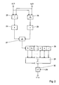
Eine Schaltungsanordnung zur Durchführung des beschriebenen Verfahrens zur Bewertung der Kohärenz einer im Raum abgetasteten Schallwelle und zur Ausgabe eines entsprechenden Bewertungsfaktors ist als Blockschaltbild in Fig. 1 und 2 angegeben, wobei Fig. 1 den Schaltungsteil für die komplexe Signalanalyse bis zur Bildung des normierten komplexen Signals pj(t) mit j=1,2 und der Schaltungsteil gemäß Fig. 2 den Phasenkorrelator zum Vergleich der beiden normierten, komplexen Signale pj(t) mit j=1,2 bis zur Ausgabe des Bewertungsfaktors C*(τ) darstellt.A circuit arrangement for carrying out the described method for evaluating the coherence of a sound wave sampled in space and for outputting a corresponding evaluation factor is indicated as a block diagram in FIGS. 1 and 2, FIG. 1 showing the circuit part for the complex signal analysis up to the formation of the standardized complex signal p j (t) with j = 1.2 and the circuit part according to FIG. 2 represents the phase correlator for comparing the two normalized, complex signals p j (t) with j = 1.2 until the evaluation factor C * (τ) is output ,
Wie aus dem Blockschaltbild der Fig. 1 hervorgeht, wird jedes
elektrische Ausgangssignal des ausgewählten Paars von
elektroakustischen Empfängern, die entsprechend dem
Ausführungsbeispiel der Fig. 3 von zwei Wandlern 11 der
Empfangsbasis 10 gebildet sind, verstärkt, abgetastet und
digitalisiert. Hierzu ist jeweils ein Verstärker 15 und eine
Abtasteinheit 16 (Sample and Hold) sowie ein Analog-Digitalwandler
17 vorgesehen. Bei einer analogen
Signalverarbeitung wird auf den A/D-Wandler 17 verzichtet.
Die Abtasteinheit 16 tastet das verstärkte Ausgangssignal in
festen Zeitintervallen Δt ab und die digitalisierten
Datensätze der Abtastwerte oder Samples werden einem Hilbert-Transformator
18 zugeführt, an dessen Ausgängen sowohl der
Real- als auch der Imaginärteil des komplexen analytischen
Signals cj(t) abgenommen werden kann. Real- und Imaginärteil
werden getrennt einerseits einem Betragsbildner 19 und
andererseits einem Dividierer 20 bzw. 21 zugeführt, dessen
anderer Eingang jeweils mit dem Ausgang des Betragsbildners
19 verbunden ist. Der normierte Realteil und der normierte
Imaginärteil werden im Addierer 22 zum Sample des normierten,
komplexen Signals pj(t) wieder zusammengesetzt. Für die in
der beschriebenen Weise bearbeiteten elektrischen
Ausgangssignale der beiden Wandler 11 des ausgewählten
Wandlerpaars ergeben sich damit die beiden normierten
komplexen Signale p1(t) und p2(t). Selbstverständlich ist es
möglich, die Hilbert-Transformation und die Normierung
unmittelbar hinter dem Verstärker 15 durchzuführen und das
normierte komplexe Signal pj(t) mittels der Abtasteinheit 16
und des A/D-Wandlers 17 abzutasten und zu digitalisieren.As can be seen from the block diagram in FIG. 1, each electrical output signal of the selected pair of electroacoustic receivers, which in accordance with the exemplary embodiment in FIG. 3 are formed by two
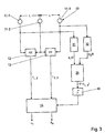
Wie Fig. 2 zeigt, werden die beiden normierten komplexen
Signale pj(t) mit j=1,2, die nur noch die Phaseninformationen
enthalten, miteinander korreliert, um das Maß ihrer
Übereinstimmung festzustellen und den Bewertungsfaktor C*(τ)
ihrer Kohärenz zu generieren. Mit den in Fig. 2 angegebenen
Komponenten der Schaltungsanordnung wird die Berechnung der
vorstehend angegebenen G1.(6) realisiert. Die Abtastwerte
oder Samples der beiden normierten komplexen Signale p1(t)
und p2(t) werden einerseits einem Addierer 23 und
andererseits einem Subtrahierer 24 zugeführt. Von der am
Ausgang des Addierers 23 ausgegebenen Summe zweier dem
gleichen Abtastzeitpunkt zugehöriger Samples und der am
Ausgang des Subtrahierers 24 ausgegebenen Differenz dieser
Samples wird in den Betragsbildnern 25 und 26 jeweils der
Betrag gebildet, und die beiden Beträge von Summe und
Differenz werden einem Subtrahierer 27 zugeführt, der den
Betrag der Differenz von dem Betrag der Summe subtrahiert.
Die so entstehenden Subtraktionsergebnisse oder Differenzen
der einzelnen Samples werden in einem Speicher, der hier
beispielhaft als Schieberegister 28 ausgeführt ist,
abgespeichert. Die Abspeicherung erfolgt für ein vorgegebenes
Zeitfenster von t=t0 bis t=t0 + N • Δt für die Samples n=1 bis
n=N, die nach jedem Zeitintervall Δt angeliefert werden. Die
Subtraktionsergebnisse der N Samples werden im Summierer 29
addiert, und im Dividierer 30 wird das Additionsergebnis
durch die Anzahl 2N der insgesamt aus beiden Signalen pj(t)
angelieferten Samples dividiert. Der am Ausgang des
Dividierers 30 abnehmbare Bewertungsfaktor für die
Phasenkohärenz der beiden Ausgangssignale nimmt den Wert +1
an, wenn beide Signale exakt korreliert sind, und den Wert -1
an, wenn beide Signale vollständig antikorreliert sind. Ein
dazwischen liegender Wert gibt ein geringeres Maß der
Übereinstimmung der beiden Signale an.As shown in FIG. 2, the two standardized complex signals p j (t) with j = 1.2, which only contain the phase information, are correlated with one another in order to determine the degree of their agreement and the evaluation factor C * (τ) of their coherence to generate. The components of the circuit arrangement specified in FIG. 2 are used to calculate the G1. (6) specified above. The samples or samples of the two standardized complex signals p 1 (t) and p 2 (t) are supplied on the one hand to an
Der so ermittelte Bewertungsfaktor C*(τ) für die Kohärenz
einer empfangenen Schallwelle wird in der mit Fig. 3
beschriebenen Sonaranlage zur Ortung einer Schallquelle für
die Bewertung der von der Sonaranlage ausgegebenen
Meßergebnisse für Peilwinkel und Entfernung der Schallquelle
verwendet. Hierzu wird in der aus drei elektroakustischen
Wandlern 11 bestehenden Empfangsbasis 10 der Sonaranlage ein
Wandlerpaar ausgewählt, im Ausführungsbeispiel der Fig. 3 das
Wandlerpaar aus den beiden äußeren Wandlern 11-1 und 11-3.
Die elektrischen Ausgangssignale der beiden äußeren Wandler
werden einer wie vorstehend beschriebenen Signalverarbeitung
unterzogen, wobei die Blöcke 31 und 32 dem in Fig. 1
dargestellten Teil der Schaltungsanordnung und Block 34 im in
Fig. 2 dargestellten Teil der Schaltungsanordnung entspricht.
Der am Ausgang vom Block 34 abnehmbare Bewertungsfaktor
C*(τ1,3), der eine Funktion der Zeitverschiebung τ1,3 zwischen
den zu vergleichenden Signalen ist, wird im
Ausführungsbeispiel der Fig. 3 dazu verwendet, die
berechneten Sonardaten 0, R0 als Gut- oder Falschwerte zu
erkennen und ggf. die Berechnung bzw. die Ausgabe der als
Falschwerte erkannten Sonardaten zu unterdrücken. Als
Falschwerte werden die Sonardaten dann ausgewiesen, wenn der
Bewertungsfaktor C*(τ1,3) unterhalb eines Vorgabewerts, z.B.
0,5 liegt. Hierzu wird der Bewertungsfaktor C*(τ1,3) über eine
entsprechende Schwelle 35 dem Rechner 14 zugeführt, so daß
der Rechner 14 nur dann die Sonardaten 0, R0 berechnet, wenn
C*(τ1,3) die Schwelle 35 übersteigt. Alternativ kann der
ausgegebene Bewertungsfaktor C*(τ1,3) auch als Konfidenzmaß
den berechneten Sonardaten 0, R0 zugeordnet werden, so daß
der Nutzer anhand der zugeordneten Konfidenzmaße selbst eine
Wertung der gemessenen Sonardaten vornehmen kann.The evaluation factor C * (τ) thus determined for the coherence of a received sound wave is used in the sonar system described with FIG. 3 for locating a sound source for evaluating the measurement results for the bearing angle and distance of the sound source output by the sonar system. For this purpose, a transducer pair is selected in the
Selbstverständlich ist es auch möglich zur Gewinnung des
Bewertungsfaktors andere Wandler 11 auszuwählen und deren
Ausgangssignale in der aufgezeigten Weise zu verarbeiten.
Möglich ist auch, die Ausgangssignale sämtlicher drei Wandler
11 miteinander paarweise in der beschriebenen Weise zu
korrelieren, so daß insgesamt drei Bewertungsfaktoren, und
zwar C*(τ1,2), C*(τ2,3) und C*(τ1,3), zur Verfügung stehen.Of course, it is also possible to select
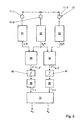
Bei der in Fig. 4 dargestellten Schaltungsanordnung wird das
vorstehend beschriebene Verfahren zur Ermittlung der
Phasenkohärenz zwischen den Ausgangssignalen zweier
elektroakustischer Empfänger einer Sonarbasis zusätzlich dazu
verwendet, bei der eingangs beschriebenen Ortung einer
Schallquelle mit Peilwinkel und Entfernung R die für die
Berechnungen der Gl. (1) und (2) erforderlichen
Zeitverschiebungen τ zwischen dem mittleren Wandler 11-2 und
den außen liegenden Wandlern 11-1 und 11-3 zu ermitteln.
Hierzu ist jedem Wandler 11 ein Block 31, 32, 33 zugeordnet,
in dem eine Signalverarbeitung durchgeführt wird, wie sie zu
Fig. 1 und 2 beschrieben worden ist. Im Block 31 wird das
normierte komplexe Signal p1(t), im Block 32 das normierte
komplexe Signal p2(t) und im Block 33 das normierte komplexe
Signal p3(t) generiert. Das Signal p1(t) wird dem Block 35,
das Signal p3(t) dem Block 36 und das Signal p2(t) sowohl dem
Block 35 als auch dem Block 36 zugeführt. Jeder Block 35 bzw.
36 entspricht dem Phasenkorrelator, dessen Schaltung in
Fig. 2 angegeben ist. Der Block 35 liefert den
Bewertungsfaktor C*(τ1,2), der abhängig ist von der
Zeitverschiebung zwischen den Ausgangssignalen der Wandler
11-1 und 11-2, und der Block 36 liefert den Bewertungsfaktor
C*(τ2,3), der eine Funktion der Zeitverschiebung zwischen den
Signalen der Wandler 11-2 und 11-3 ist. Jedem Block 35, 36
ist eine Kalibirierstufe 38 bzw. 39 nachgeordnet. In der
Kalibirierstufe 38 ist der Bewertungsfaktor C*(τ1,2) als
Funktion der Zeitverschiebung (τ1,2) abgelegt. In der
Kalibirierstufe 39 ist der Bewertungsfaktor C*(τ2,3) als
Funktion der Zeitverschiebung (τ2,3) abgelegt. Mit dem am
Ausgang der Blöcke 35 und 36 anstehenden Bewertungsfaktoren
C*(τ1,2) und C*(τ2,3) werden aus den Kalibirierstufen 38, 39
die Zeitverschiebungen (τ1,2) und (τ2,3) ausgelesen und dem
Rechner 14 zugeführt. Der Rechner 14 berechnet nach den Gl.
(1) und (2) die Sonardaten, Peilwinkel 0 und Entfernung R0.
Um ausschließlich vertrauenswürdige Sonardaten zu erhalten,
werden nur solche Bewertungsfaktoren in die Kalibirierstufen
38 und 39 eingegeben, die oberhalb eines vorgegebenen
Schwellwerts, der beispielsweise bei C*=0,5 festgesetzt ist,
liegen. Hierzu ist jeweils zwischen dem Block 35 und der
Kalibirierstufe 38 bzw. dem Block 36 und der Kalibrierstufe
39 eine Schwelle 40 bzw. 41 eingefügt.In the circuit arrangement shown in Fig. 4, the method described above for determining the phase coherence between the output signals of two electroacoustic receivers of a sonar base is additionally used in the above-described location of a sound source with bearing angle and distance R which is used for the calculations of Eq. (1) and (2) required time shifts τ between the middle converter 11-2 and the outside converters 11-1 and 11-3. For this purpose, each
Die Empfänger der Empfangsbasis 10 können, wie beschrieben,
von einzelnen Wandlern 11, die eine Dipol- oder
Rundumcharakteristik aufweisen, gebildet werden. Als
elektroakustische Empfänger der Empfangsbasis 10 können aber
auch Gruppen von elektroakustischen Wandlern 11 verwendet
werden, die in Horizontalrichtung oder in Vertikalrichtung
voneinander beabstandet linear angeordnet sind. Im Falle der
vertikalen Anordnung spricht man von sog. Staves. In solchen
Fälle wird als das wie beschrieben zu verarbeitende
Ausgangssignal des Empfängers ein aus den Ausgangssignalen
der Wandlergruppen abgeleitetes Gruppensignal verwendet.As described, the receivers of the
Das erfindungsgemäße Verfahren kann auch dazu benutzt werden, die lineare Ausrichtung der in einer sog. Schleppantenne angeordneten elektroakustischen Wandlern zu bewerten. Der Bewertungsfaktor läßt dabei Rückschlüsse auf den Versatz eines Wandlers bezüglich der linearen Ausrichtung zu.The method according to the invention can also be used to the linear alignment of the in a so-called trailing antenna arranged electro-acoustic transducers to evaluate. The The evaluation factor allows conclusions to be drawn about the offset of a transducer with respect to the linear alignment.
Claims (13)
Applications Claiming Priority (2)
| Application Number | Priority Date | Filing Date | Title |
|---|---|---|---|
| DE2001136026 DE10136026A1 (en) | 2001-07-25 | 2001-07-25 | Procedure for evaluating the coherence of sound waves |
| DE10136026 | 2001-07-25 |
Publications (3)
| Publication Number | Publication Date |
|---|---|
| EP1281982A2 true EP1281982A2 (en) | 2003-02-05 |
| EP1281982A3 EP1281982A3 (en) | 2004-01-07 |
| EP1281982B1 EP1281982B1 (en) | 2013-01-09 |
Family
ID=7692913
Family Applications (1)
| Application Number | Title | Priority Date | Filing Date |
|---|---|---|---|
| EP20020012275 Expired - Lifetime EP1281982B1 (en) | 2001-07-25 | 2002-06-05 | Method and circuit for the evaluation of the coherence of acoustic waves |
Country Status (2)
| Country | Link |
|---|---|
| EP (1) | EP1281982B1 (en) |
| DE (1) | DE10136026A1 (en) |
Cited By (1)
| Publication number | Priority date | Publication date | Assignee | Title |
|---|---|---|---|---|
| CN111856474A (en) * | 2020-07-30 | 2020-10-30 | 重庆大学 | A Subarray-Based Conditional Coherence Coefficient Ultrasound Imaging Method in Space-Time Domain |
Citations (1)
| Publication number | Priority date | Publication date | Assignee | Title |
|---|---|---|---|---|
| US4910719A (en) | 1987-04-24 | 1990-03-20 | Thomson-Csf | Passive sound telemetry method |
Family Cites Families (3)
| Publication number | Priority date | Publication date | Assignee | Title |
|---|---|---|---|---|
| DE4432532A1 (en) * | 1994-09-13 | 1996-03-14 | Stn Atlas Elektronik Gmbh | Process for the elimination of structure-borne noise |
| FR2800879B1 (en) * | 1999-11-09 | 2007-03-02 | France Etat | ASSOCIATED METHODS AND DEVICES FOR DETERMINING THE FORM OF A LINEAR ANTENNA AND OF TAPERED AMBIGUE LEVERAGE |
| DE10036291C1 (en) * | 2000-07-26 | 2001-10-31 | Stn Atlas Elektronik Gmbh | Interference suppression method for group signals in sonar location device uses multiplication of group signal with weighting signal for eliminating reception signal phase errors |
-
2001
- 2001-07-25 DE DE2001136026 patent/DE10136026A1/en not_active Withdrawn
-
2002
- 2002-06-05 EP EP20020012275 patent/EP1281982B1/en not_active Expired - Lifetime
Patent Citations (1)
| Publication number | Priority date | Publication date | Assignee | Title |
|---|---|---|---|---|
| US4910719A (en) | 1987-04-24 | 1990-03-20 | Thomson-Csf | Passive sound telemetry method |
Cited By (2)
| Publication number | Priority date | Publication date | Assignee | Title |
|---|---|---|---|---|
| CN111856474A (en) * | 2020-07-30 | 2020-10-30 | 重庆大学 | A Subarray-Based Conditional Coherence Coefficient Ultrasound Imaging Method in Space-Time Domain |
| CN111856474B (en) * | 2020-07-30 | 2023-07-25 | 重庆大学 | A subarray-based ultrasonic imaging method with conditional coherence coefficient in space-time domain |
Also Published As
| Publication number | Publication date |
|---|---|
| EP1281982B1 (en) | 2013-01-09 |
| DE10136026A1 (en) | 2003-02-20 |
| EP1281982A3 (en) | 2004-01-07 |
Similar Documents
| Publication | Publication Date | Title |
|---|---|---|
| DE69805484T2 (en) | Method for focusing an ultrasound signal and device for an ultrasound imaging system | |
| DE68913499T2 (en) | Discrete autofocus setting for imaging in a radar with synthetic aperture and very high resolution. | |
| DE19511751C2 (en) | Process for the reconstruction of signals disturbed by multipath propagation | |
| DE69725670T2 (en) | Highly accurate time-frequency signal analysis with low distortion using rotated window spectrograms | |
| DE2816332C3 (en) | Device for identifying a moving sound source | |
| DE19511752A1 (en) | Process for high-resolution evaluation of signals for one- or two-dimensional direction or frequency estimation | |
| DE2500698C3 (en) | Automatic direction finder | |
| DE3408404C2 (en) | Device for radar simulation | |
| EP4196818B1 (en) | Method and device for determining frequency disturbances in a received signal of an active multi-channel sar system | |
| EP3610289B1 (en) | Processing unit for a sonar system for processing hydrophone signals and sonar system and method | |
| DE2753764A1 (en) | METHOD AND DEVICE FOR RADIO LEVELING | |
| DE69011566T2 (en) | Acoustic detection device. | |
| DE3108594A1 (en) | Pulse-Doppler radar receiver | |
| EP1281982A2 (en) | Method for the evaluation of the coherency of acoustic waves | |
| EP1271175A1 (en) | Method for determining the position of a sound emitting target | |
| EP1160581B1 (en) | Method for determining the angle of arrival of sound waves | |
| EP2589977A1 (en) | Method and apparatus for correcting systematic DF errors | |
| EP2472282B1 (en) | Method for determining one or more relative directions as target bearing or target bearings and device for performing the method | |
| DE10353292B3 (en) | Method of forming a group signal | |
| EP1176428B1 (en) | Method for improving the signal-to-noise ratio of a sonar array | |
| DE3345021C2 (en) | ||
| EP2480907B1 (en) | Method and device for locating sound-emitting targets | |
| EP1308745B1 (en) | Method for passive position determination of sound emitting targets | |
| EP1107016B1 (en) | Method for detecting and locating targets | |
| EP1756983A1 (en) | Method for detecting targets |
Legal Events
| Date | Code | Title | Description |
|---|---|---|---|
| PUAI | Public reference made under article 153(3) epc to a published international application that has entered the european phase |
Free format text: ORIGINAL CODE: 0009012 |
|
| AK | Designated contracting states |
Designated state(s): AT BE CH CY DE DK ES FI FR GB GR IE IT LI LU MC NL PT SE TR |
|
| AX | Request for extension of the european patent |
Extension state: AL LT LV MK RO SI |
|
| RAP1 | Party data changed (applicant data changed or rights of an application transferred) |
Owner name: ATLAS ELEKTRONIK GMBH |
|
| PUAL | Search report despatched |
Free format text: ORIGINAL CODE: 0009013 |
|
| AK | Designated contracting states |
Kind code of ref document: A3 Designated state(s): AT BE CH CY DE DK ES FI FR GB GR IE IT LI LU MC NL PT SE TR |
|
| AX | Request for extension of the european patent |
Extension state: AL LT LV MK RO SI |
|
| 17P | Request for examination filed |
Effective date: 20031203 |
|
| AKX | Designation fees paid |
Designated state(s): AT BE CH CY DE DK ES FI FR GB GR IE IT LI LU MC NL PT SE TR |
|
| 17Q | First examination report despatched |
Effective date: 20080711 |
|
| GRAP | Despatch of communication of intention to grant a patent |
Free format text: ORIGINAL CODE: EPIDOSNIGR1 |
|
| GRAS | Grant fee paid |
Free format text: ORIGINAL CODE: EPIDOSNIGR3 |
|
| GRAA | (expected) grant |
Free format text: ORIGINAL CODE: 0009210 |
|
| AK | Designated contracting states |
Kind code of ref document: B1 Designated state(s): AT BE CH CY DE DK ES FI FR GB GR IE IT LI LU MC NL PT SE TR |
|
| REG | Reference to a national code |
Ref country code: GB Ref legal event code: FG4D Free format text: NOT ENGLISH |
|
| REG | Reference to a national code |
Ref country code: CH Ref legal event code: EP Ref country code: AT Ref legal event code: REF Ref document number: 593053 Country of ref document: AT Kind code of ref document: T Effective date: 20130115 |
|
| REG | Reference to a national code |
Ref country code: IE Ref legal event code: FG4D Free format text: LANGUAGE OF EP DOCUMENT: GERMAN |
|
| REG | Reference to a national code |
Ref country code: DE Ref legal event code: R096 Ref document number: 50215678 Country of ref document: DE Effective date: 20130307 |
|
| REG | Reference to a national code |
Ref country code: SE Ref legal event code: TRGR |
|
| REG | Reference to a national code |
Ref country code: NL Ref legal event code: VDEP Effective date: 20130109 |
|
| PG25 | Lapsed in a contracting state [announced via postgrant information from national office to epo] |
Ref country code: ES Free format text: LAPSE BECAUSE OF FAILURE TO SUBMIT A TRANSLATION OF THE DESCRIPTION OR TO PAY THE FEE WITHIN THE PRESCRIBED TIME-LIMIT Effective date: 20130420 Ref country code: CY Free format text: LAPSE BECAUSE OF FAILURE TO SUBMIT A TRANSLATION OF THE DESCRIPTION OR TO PAY THE FEE WITHIN THE PRESCRIBED TIME-LIMIT Effective date: 20130109 |
|
| PG25 | Lapsed in a contracting state [announced via postgrant information from national office to epo] |
Ref country code: FI Free format text: LAPSE BECAUSE OF FAILURE TO SUBMIT A TRANSLATION OF THE DESCRIPTION OR TO PAY THE FEE WITHIN THE PRESCRIBED TIME-LIMIT Effective date: 20130109 Ref country code: GR Free format text: LAPSE BECAUSE OF FAILURE TO SUBMIT A TRANSLATION OF THE DESCRIPTION OR TO PAY THE FEE WITHIN THE PRESCRIBED TIME-LIMIT Effective date: 20130410 Ref country code: NL Free format text: LAPSE BECAUSE OF FAILURE TO SUBMIT A TRANSLATION OF THE DESCRIPTION OR TO PAY THE FEE WITHIN THE PRESCRIBED TIME-LIMIT Effective date: 20130109 Ref country code: PT Free format text: LAPSE BECAUSE OF FAILURE TO SUBMIT A TRANSLATION OF THE DESCRIPTION OR TO PAY THE FEE WITHIN THE PRESCRIBED TIME-LIMIT Effective date: 20130509 |
|
| PG25 | Lapsed in a contracting state [announced via postgrant information from national office to epo] |
Ref country code: DK Free format text: LAPSE BECAUSE OF FAILURE TO SUBMIT A TRANSLATION OF THE DESCRIPTION OR TO PAY THE FEE WITHIN THE PRESCRIBED TIME-LIMIT Effective date: 20130109 |
|
| PLBE | No opposition filed within time limit |
Free format text: ORIGINAL CODE: 0009261 |
|
| STAA | Information on the status of an ep patent application or granted ep patent |
Free format text: STATUS: NO OPPOSITION FILED WITHIN TIME LIMIT |
|
| 26N | No opposition filed |
Effective date: 20131010 |
|
| BERE | Be: lapsed |
Owner name: ATLAS ELEKTRONIK G.M.B.H. Effective date: 20130630 |
|
| PG25 | Lapsed in a contracting state [announced via postgrant information from national office to epo] |
Ref country code: IT Free format text: LAPSE BECAUSE OF FAILURE TO SUBMIT A TRANSLATION OF THE DESCRIPTION OR TO PAY THE FEE WITHIN THE PRESCRIBED TIME-LIMIT Effective date: 20130109 |
|
| PG25 | Lapsed in a contracting state [announced via postgrant information from national office to epo] |
Ref country code: MC Free format text: LAPSE BECAUSE OF FAILURE TO SUBMIT A TRANSLATION OF THE DESCRIPTION OR TO PAY THE FEE WITHIN THE PRESCRIBED TIME-LIMIT Effective date: 20130109 |
|
| REG | Reference to a national code |
Ref country code: CH Ref legal event code: PL |
|
| REG | Reference to a national code |
Ref country code: DE Ref legal event code: R097 Ref document number: 50215678 Country of ref document: DE Effective date: 20131010 |
|
| REG | Reference to a national code |
Ref country code: IE Ref legal event code: MM4A |
|
| PG25 | Lapsed in a contracting state [announced via postgrant information from national office to epo] |
Ref country code: BE Free format text: LAPSE BECAUSE OF NON-PAYMENT OF DUE FEES Effective date: 20130630 |
|
| PG25 | Lapsed in a contracting state [announced via postgrant information from national office to epo] |
Ref country code: CH Free format text: LAPSE BECAUSE OF NON-PAYMENT OF DUE FEES Effective date: 20130630 Ref country code: IE Free format text: LAPSE BECAUSE OF NON-PAYMENT OF DUE FEES Effective date: 20130605 Ref country code: LI Free format text: LAPSE BECAUSE OF NON-PAYMENT OF DUE FEES Effective date: 20130630 |
|
| REG | Reference to a national code |
Ref country code: AT Ref legal event code: MM01 Ref document number: 593053 Country of ref document: AT Kind code of ref document: T Effective date: 20130605 |
|
| PG25 | Lapsed in a contracting state [announced via postgrant information from national office to epo] |
Ref country code: AT Free format text: LAPSE BECAUSE OF NON-PAYMENT OF DUE FEES Effective date: 20130605 |
|
| PG25 | Lapsed in a contracting state [announced via postgrant information from national office to epo] |
Ref country code: LU Free format text: LAPSE BECAUSE OF NON-PAYMENT OF DUE FEES Effective date: 20130605 |
|
| REG | Reference to a national code |
Ref country code: FR Ref legal event code: PLFP Year of fee payment: 15 |
|
| PGFP | Annual fee paid to national office [announced via postgrant information from national office to epo] |
Ref country code: GB Payment date: 20160621 Year of fee payment: 15 Ref country code: DE Payment date: 20160621 Year of fee payment: 15 |
|
| PGFP | Annual fee paid to national office [announced via postgrant information from national office to epo] |
Ref country code: FR Payment date: 20160627 Year of fee payment: 15 Ref country code: TR Payment date: 20160524 Year of fee payment: 15 Ref country code: SE Payment date: 20160620 Year of fee payment: 15 |
|
| REG | Reference to a national code |
Ref country code: DE Ref legal event code: R119 Ref document number: 50215678 Country of ref document: DE |
|
| REG | Reference to a national code |
Ref country code: SE Ref legal event code: EUG |
|
| GBPC | Gb: european patent ceased through non-payment of renewal fee |
Effective date: 20170605 |
|
| PG25 | Lapsed in a contracting state [announced via postgrant information from national office to epo] |
Ref country code: SE Free format text: LAPSE BECAUSE OF NON-PAYMENT OF DUE FEES Effective date: 20170606 |
|
| REG | Reference to a national code |
Ref country code: FR Ref legal event code: ST Effective date: 20180228 |
|
| PG25 | Lapsed in a contracting state [announced via postgrant information from national office to epo] |
Ref country code: GB Free format text: LAPSE BECAUSE OF NON-PAYMENT OF DUE FEES Effective date: 20170605 Ref country code: DE Free format text: LAPSE BECAUSE OF NON-PAYMENT OF DUE FEES Effective date: 20180103 |
|
| PG25 | Lapsed in a contracting state [announced via postgrant information from national office to epo] |
Ref country code: FR Free format text: LAPSE BECAUSE OF NON-PAYMENT OF DUE FEES Effective date: 20170630 |
|
| PG25 | Lapsed in a contracting state [announced via postgrant information from national office to epo] |
Ref country code: TR Free format text: LAPSE BECAUSE OF NON-PAYMENT OF DUE FEES Effective date: 20170605 |