EP1281982A2 - Procédé d'évaluation de la cohérence des ondes acoustiques - Google Patents
Procédé d'évaluation de la cohérence des ondes acoustiques Download PDFInfo
- Publication number
- EP1281982A2 EP1281982A2 EP02012275A EP02012275A EP1281982A2 EP 1281982 A2 EP1281982 A2 EP 1281982A2 EP 02012275 A EP02012275 A EP 02012275A EP 02012275 A EP02012275 A EP 02012275A EP 1281982 A2 EP1281982 A2 EP 1281982A2
- Authority
- EP
- European Patent Office
- Prior art keywords
- electroacoustic
- evaluation factor
- output signals
- amount
- distance
- Prior art date
- Legal status (The legal status is an assumption and is not a legal conclusion. Google has not performed a legal analysis and makes no representation as to the accuracy of the status listed.)
- Granted
Links
Images

Classifications
-
- G—PHYSICS
- G01—MEASURING; TESTING
- G01S—RADIO DIRECTION-FINDING; RADIO NAVIGATION; DETERMINING DISTANCE OR VELOCITY BY USE OF RADIO WAVES; LOCATING OR PRESENCE-DETECTING BY USE OF THE REFLECTION OR RERADIATION OF RADIO WAVES; ANALOGOUS ARRANGEMENTS USING OTHER WAVES
- G01S3/00—Direction-finders for determining the direction from which infrasonic, sonic, ultrasonic or electromagnetic waves, or particle emission, not having a directional significance, are being received
- G01S3/80—Direction-finders for determining the direction from which infrasonic, sonic, ultrasonic or electromagnetic waves, or particle emission, not having a directional significance, are being received using ultrasonic, sonic or infrasonic waves
- G01S3/802—Systems for determining direction or deviation from predetermined direction
- G01S3/808—Systems for determining direction or deviation from predetermined direction using transducers spaced apart and measuring phase or time difference between signals therefrom, i.e. path-difference systems
- G01S3/8083—Systems for determining direction or deviation from predetermined direction using transducers spaced apart and measuring phase or time difference between signals therefrom, i.e. path-difference systems determining direction of source
-
- G—PHYSICS
- G01—MEASURING; TESTING
- G01S—RADIO DIRECTION-FINDING; RADIO NAVIGATION; DETERMINING DISTANCE OR VELOCITY BY USE OF RADIO WAVES; LOCATING OR PRESENCE-DETECTING BY USE OF THE REFLECTION OR RERADIATION OF RADIO WAVES; ANALOGOUS ARRANGEMENTS USING OTHER WAVES
- G01S3/00—Direction-finders for determining the direction from which infrasonic, sonic, ultrasonic or electromagnetic waves, or particle emission, not having a directional significance, are being received
- G01S3/80—Direction-finders for determining the direction from which infrasonic, sonic, ultrasonic or electromagnetic waves, or particle emission, not having a directional significance, are being received using ultrasonic, sonic or infrasonic waves
- G01S3/801—Details
Definitions
- the invention relates to a method for evaluating the Coherence of sound waves that are spatial extensive reception base with several, from each other spaced, electroacoustic receiver of a sonar system spread.
- a reception base is used with three electroacoustic transducers which are arranged on a straight line and are at a distance from one another which is a multiple of the wavelength of that from the sound source radiated sound.
- the electrical output signals of the middle transducer are cross-correlated with the output signals of each outer transducer and so the time shift between the output signals of the transducers is determined.
- the invention has for its object a method to indicate with which with little Signal processing effort the coherence of one Base of reception of a sonar system received sound waves specify and thus have the quality of the measurement results checked.
- the inventive method with the features of Claim 1 has the advantage that it is low Additional effort parallel to known methods of detection, Location and classification of sound radiating targets can be applied and existing hardware and Software components of the sonar system can be used.
- the method according to the invention enables the of the measurement results supplied by the measurement method and gives the User with which confidence measure he of the Reliability of the measured, current sonar data can, so that he uses a quality assessment of a Multitude of measured sonar data much faster the with high probability correct sonar data filter out and then an early decision can support.
- the two standardized complex signals in a time window is scanned at the same times and the two belonging to the same time Samples added. From the resulting sum, the Amount formed. Then the amounts of the sums are added and an average is formed from the addition result and output as an evaluation factor.
- the calculation algorithm does not directly calculate the amounts of the sums or of the differences added and averaged and then the Subtracted mean values, but after forming the amount of Sum and the amount of the difference of two each Samples already the amount of the difference from the amount of the sums subtracted and the addition and averaging applied to the subtraction results thus obtained.
- the complex signal using a Hilbert transform generated and its normalization by dividing the complex Signal made by its amount.
- the Hilbert transformation and normalization can be anywhere in the signal processing of the output signals, so that existing hardware and software components for a existing measuring method for measuring sonar data optimally to implement the method according to the invention minimal additional effort can be used.
- Digitization of the output signals in the signal processing path can the Hilbert transformation on the digital records of the output signals are applied and through FIR filter structures respectively.
- electroacoustic transducers with dipole or All-round characteristics can be used. Also groups of electroacoustic transducers operating in horizontal or are arranged at a distance from each other in the vertical direction, can serve as recipients. That of the invention Signal processing subjected to electrical output signal of the The preprocessed group signal is then the receiver Converter group.
- the inventive method in connection with a Process for the passive location of a water Sound source using three linearly spaced apart arranged, electroacoustic transducers, the so-called PRS process, used by using the middle converter and a selected pair of each outer transducer electroacoustic receivers is formed and from the like described evaluation factors the time or Phase shifts between the middle converter and the both outer transducers determined and in a known manner Calculation of bearing angle and distance of the sound source be used.
- a spatially extensive reception base with several electro-acoustic receivers spaced apart from one another is used in sonar technology.
- This reception base 10 has three receivers, each of which is formed by an electroacoustic transducer 11.
- the three transducers 11 are arranged exactly on a straight line at a distance L from one another.
- the middle converter 11-2 is arranged amidships near the tower and the two outer converters 11-1 and 11-2 are arranged near the stern and the bow.
- the phase or time shifts between the electrical output signals of the middle transducer 11-2 and each of the outer transducers 11-1 and 11-3 are determined and from this the bearing angle ⁇ 0 and the distance R 0 according to Eq. (1) and (2) calculated.
- the usually amplified and digitized output signals of the converters 11-1 and 11-2 on the one hand and 11-2 and 11-3 on the other hand are each fed to a cross correlator 12 and 13, respectively, which has the time shift ⁇ 1,2 and ⁇ 2,3 between the output signals determined.
- the information quality of the location procedure will increase Coherence of the and sound wave received by the transducers 11.
- the the evaluation factor gained is an indication that with what probability the accuracy of the sonar data can be assumed.
- To gain this Evaluation factor is in the reception base 10 with the three Transducers 11 selected at least one pair of transducers and the Coherence of the phases of the electrical output signals of the determined two selected transducers 11.
- a complex signal c j (t) that can be written is generated from each output signal of the converter pair, which represents a real signal s j (t) by means of a Hilbert transform H (s j (t))
- a j (t) ⁇ exp [i ⁇ ⁇ j (t)] represents an analytical description of the signal.
- a j (t) describes the envelope of s j (t) and ⁇ j (t) the current phase.
- the amount of the difference is subtracted from the amount of the sum and the addition and the averaging are applied to the subtraction results obtained in this way, so that after subtracting the amount of the sum and the amount of the difference from two mutually associated samples for the calculation of the phase coherence C * ( ⁇ ) the following equation is obtained:
- the formation of the complex analytical signals c j (t) by means of the Hilbert transform H (s j (t)) and the subsequent normalization can be inserted at any point in the direct processing path of the (real) output signals of the two receivers.
- the Hilbert transformation is applied to the digital samples of the scanning signals, the digital samples being used as samples of the time window.
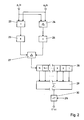
- each electrical output signal of the selected pair of electroacoustic receivers which in accordance with the exemplary embodiment in FIG. 3 are formed by two transducers 11 of the reception base 10, is amplified, sampled and digitized.
- an amplifier 15 and a sampling unit 16 sample and hold
- an analog-digital converter 17 are provided.
- the A / D converter 17 is dispensed with.
- the sampling unit 16 samples the amplified output signal at fixed time intervals ⁇ t and the digitized data sets of the samples or samples are fed to a Hilbert transformer 18, at the outputs of which both the real and the imaginary part of the complex analytical signal c j (t) are taken can.
- the real and imaginary parts are fed separately on the one hand to an amount generator 19 and on the other hand to a divider 20 or 21, the other input of which is connected to the output of the amount generator 19.
- the normalized real part and the normalized imaginary part are reassembled in the adder 22 to the sample of the normalized, complex signal p j (t).
- the two standardized complex signals p 1 (t) and p 2 (t) thus result for the electrical output signals of the two converters 11 of the selected converter pair processed in the manner described.
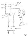
- the components of the circuit arrangement specified in FIG. 2 are used to calculate the G1. (6) specified above.
- the samples or samples of the two standardized complex signals p 1 (t) and p 2 (t) are supplied on the one hand to an adder 23 and on the other hand to a subtractor 24.
- the sum of the sum of two samples belonging to the same sampling time and the difference of these samples output at the output of the subtractor 24 is output in the amount formers 25 and 26, and the two amounts of sum and difference become a subtractor 27 fed, which subtracts the amount of the difference from the amount of the sum.
- the subtraction results of the N samples are added in the summer 29, and in the divider 30 the addition result is divided by the number 2N of the samples delivered in total from both signals p j (t).
- the evaluation factor for the phase coherence of the two output signals which can be removed at the output of the divider 30, assumes the value +1 if both signals are exactly correlated and the value -1 if both signals are completely anti-correlated. An intermediate value indicates a lower degree of agreement between the two signals.
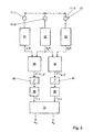
- the evaluation factor C * ( ⁇ ) thus determined for the coherence of a received sound wave is used in the sonar system described with FIG. 3 for locating a sound source for evaluating the measurement results for the bearing angle and distance of the sound source output by the sonar system.
- a transducer pair is selected in the reception base 10 of the sonar system consisting of three electroacoustic transducers 11, in the exemplary embodiment in FIG. 3 the transducer pair from the two outer transducers 11-1 and 11-3.
- the electrical output signals of the two outer transducers are subjected to signal processing as described above, blocks 31 and 32 corresponding to the part of the circuit arrangement shown in FIG. 1 and block 34 to the part of the circuit arrangement shown in FIG. 2.
- the sonar data are shown as false values if the evaluation factor C * ( ⁇ 1.3 ) is below a default value, for example 0.5.
- the evaluation factor C * ( ⁇ 1.3 ) is fed to the computer 14 via a corresponding threshold 35, so that the computer 14 only calculates the sonar data ⁇ 0 , R 0 if C * ( ⁇ 1.3 ) the threshold 35 exceeds.
- the output evaluation factor C * ( ⁇ 1.3 ) can also be assigned as a confidence measure to the calculated sonar data ⁇ 0 , R 0 , so that the user can carry out an evaluation of the measured sonar data based on the assigned confidence measures.
- each converter 11 is assigned a block 31, 32, 33 in which signal processing is carried out, as has been described for FIGS. 1 and 2.
- block 31 the normalized complex signal p 1 (t) in block 32, the normalized complex signal p 2 (t) and in the block 33, the normalized complex signal p 3 (t) is generated.
- the signal p 1 (t) is fed to the block 35, the signal p 3 (t) to the block 36 and the signal p 2 (t) to both the block 35 and the block 36.
- Each block 35 and 36 corresponds to the phase correlator, the circuit of which is indicated in FIG. 2.
- Block 35 provides the evaluation factor C * ( ⁇ 1,2 ), which is dependent on the time shift between the output signals of the converters 11-1 and 11-2, and block 36 supplies the evaluation factor C * ( ⁇ 2,3 ), which is a function of the time shift between the signals from transducers 11-2 and 11-3.
- Each block 35, 36 is followed by a calibration stage 38 or 39. In the Kalibirier tone 38 of the factor C * ( ⁇ 1.2) as a function of time shift ( ⁇ 1.2) are stored.
- the receivers of the reception base 10 can of individual transducers 11, which are a dipole or Have all-round characteristics, are formed.
- electroacoustic receivers of the reception base 10 can groups of electroacoustic transducers 11 are also used be in the horizontal direction or in the vertical direction are linearly spaced from each other. In case of vertical arrangement is called Staves. In such Cases will be processed as described Output signal of the receiver on from the output signals group signal derived from the converter groups.
- the method according to the invention can also be used to the linear alignment of the in a so-called trailing antenna arranged electro-acoustic transducers to evaluate.
- the evaluation factor allows conclusions to be drawn about the offset of a transducer with respect to the linear alignment.
Landscapes
- Physics & Mathematics (AREA)
- Engineering & Computer Science (AREA)
- General Physics & Mathematics (AREA)
- Radar, Positioning & Navigation (AREA)
- Remote Sensing (AREA)
- Measurement Of Velocity Or Position Using Acoustic Or Ultrasonic Waves (AREA)
Applications Claiming Priority (2)
| Application Number | Priority Date | Filing Date | Title |
|---|---|---|---|
| DE2001136026 DE10136026A1 (de) | 2001-07-25 | 2001-07-25 | Verfahren zur Bewertung der Kohärenz von Schallwellen |
| DE10136026 | 2001-07-25 |
Publications (3)
| Publication Number | Publication Date |
|---|---|
| EP1281982A2 true EP1281982A2 (fr) | 2003-02-05 |
| EP1281982A3 EP1281982A3 (fr) | 2004-01-07 |
| EP1281982B1 EP1281982B1 (fr) | 2013-01-09 |
Family
ID=7692913
Family Applications (1)
| Application Number | Title | Priority Date | Filing Date |
|---|---|---|---|
| EP20020012275 Expired - Lifetime EP1281982B1 (fr) | 2001-07-25 | 2002-06-05 | Procédé et circuit d'évaluation de la cohérence des ondes acoustiques |
Country Status (2)
| Country | Link |
|---|---|
| EP (1) | EP1281982B1 (fr) |
| DE (1) | DE10136026A1 (fr) |
Cited By (1)
| Publication number | Priority date | Publication date | Assignee | Title |
|---|---|---|---|---|
| CN111856474A (zh) * | 2020-07-30 | 2020-10-30 | 重庆大学 | 一种基于子阵的空时域条件相干系数超声成像方法 |
Citations (1)
| Publication number | Priority date | Publication date | Assignee | Title |
|---|---|---|---|---|
| US4910719A (en) | 1987-04-24 | 1990-03-20 | Thomson-Csf | Passive sound telemetry method |
Family Cites Families (3)
| Publication number | Priority date | Publication date | Assignee | Title |
|---|---|---|---|---|
| DE4432532A1 (de) * | 1994-09-13 | 1996-03-14 | Stn Atlas Elektronik Gmbh | Verfahren zur Befreiung von Körperschallstörungen |
| FR2800879B1 (fr) * | 1999-11-09 | 2007-03-02 | France Etat | Procedes et dispositifs associes de determination de la forme d'une antenne lineaire et de lever d'ambiguite conique |
| DE10036291C1 (de) * | 2000-07-26 | 2001-10-31 | Stn Atlas Elektronik Gmbh | Verfahren zur Störbefreiung von Gruppensignalen |
-
2001
- 2001-07-25 DE DE2001136026 patent/DE10136026A1/de not_active Withdrawn
-
2002
- 2002-06-05 EP EP20020012275 patent/EP1281982B1/fr not_active Expired - Lifetime
Patent Citations (1)
| Publication number | Priority date | Publication date | Assignee | Title |
|---|---|---|---|---|
| US4910719A (en) | 1987-04-24 | 1990-03-20 | Thomson-Csf | Passive sound telemetry method |
Cited By (2)
| Publication number | Priority date | Publication date | Assignee | Title |
|---|---|---|---|---|
| CN111856474A (zh) * | 2020-07-30 | 2020-10-30 | 重庆大学 | 一种基于子阵的空时域条件相干系数超声成像方法 |
| CN111856474B (zh) * | 2020-07-30 | 2023-07-25 | 重庆大学 | 一种基于子阵的空时域条件相干系数超声成像方法 |
Also Published As
| Publication number | Publication date |
|---|---|
| EP1281982B1 (fr) | 2013-01-09 |
| DE10136026A1 (de) | 2003-02-20 |
| EP1281982A3 (fr) | 2004-01-07 |
Similar Documents
| Publication | Publication Date | Title |
|---|---|---|
| DE69805484T2 (de) | Verfahren zur Fokussierung eines Ultraschallsignals und Gerät für ein Ultraschallabbildungssystem | |
| DE68913499T2 (de) | Diskrete Autofokus-Einstellung für die Abbildungserzeugung in einem Radar mit synthetischer Apertur und sehr hoher Auflösung. | |
| DE19511751C2 (de) | Verfahren zur Rekonstruktion von durch Mehrwegeausbreitung gestörten Signalen | |
| DE69725670T2 (de) | Hochgenaue Zeit-Frequenz-Signalanalyse mit niedriger Verzerrung unter Verwendung gedrehter Fensterspektrogramme | |
| DE2816332C3 (de) | Vorrichtung zur Identifizierung einer bewegten Schallquelle | |
| DE19511752A1 (de) | Verfahren zum hochauflösenden Auswerten von Signalen zur ein- oder zweidimensionalen Richtungs- oder Frequenzschätzung | |
| DE2500698C3 (de) | Automatischer Peiler | |
| DE3408404C2 (de) | Vorrichtung zur Radarsimulation | |
| EP4196818B1 (fr) | Procédé et dispositif permettant de déterminer des perturbations de fréquence dans un signal reçu d'un système sar à canaux multiples actif | |
| EP3610289B1 (fr) | Unité de traitement pour un système sonar servant à traiter des signaux d'hydrophone ainsi que système sonar et procédé | |
| DE2753764A1 (de) | Verfahren und vorrichtung zur funkpeilung | |
| DE69011566T2 (de) | Akustisches Detektionsgerät. | |
| DE3108594A1 (de) | Pulsdoppler-radarempfaenger | |
| EP1281982A2 (fr) | Procédé d'évaluation de la cohérence des ondes acoustiques | |
| EP1271175A1 (fr) | Procédé pour déterminer la position d'une cible émettant du son | |
| EP1160581B1 (fr) | Procédé pour déterminer la direction d'incidence des ondes sonores | |
| EP2589977A1 (fr) | Procédé et dispositif de correction d'une erreur de relèvement systématique | |
| EP2472282B1 (fr) | Procédé de détermination d'une ou plusieurs directions relatives comme relèvement de cible ou relèvements de cible ainsi que dispositif d'exécution du procédé | |
| DE10353292B3 (de) | Verfahren zur Bildung eines Gruppensignals | |
| EP1176428B1 (fr) | Procede pour ameliorer le rapport signal sur bruit d'un réseau d'antennes sonar | |
| DE3345021C2 (fr) | ||
| EP2480907B1 (fr) | Procédé et dispositif de localisation de cibles émettant un rayonnement | |
| EP1308745B1 (fr) | Procédé de localisation passif des cibles rayonnants des ondes sonores | |
| EP1107016B1 (fr) | Procédé de détection et de localisation de cibles | |
| EP1756983A1 (fr) | Procede pour detecter des cibles |
Legal Events
| Date | Code | Title | Description |
|---|---|---|---|
| PUAI | Public reference made under article 153(3) epc to a published international application that has entered the european phase |
Free format text: ORIGINAL CODE: 0009012 |
|
| AK | Designated contracting states |
Designated state(s): AT BE CH CY DE DK ES FI FR GB GR IE IT LI LU MC NL PT SE TR |
|
| AX | Request for extension of the european patent |
Extension state: AL LT LV MK RO SI |
|
| RAP1 | Party data changed (applicant data changed or rights of an application transferred) |
Owner name: ATLAS ELEKTRONIK GMBH |
|
| PUAL | Search report despatched |
Free format text: ORIGINAL CODE: 0009013 |
|
| AK | Designated contracting states |
Kind code of ref document: A3 Designated state(s): AT BE CH CY DE DK ES FI FR GB GR IE IT LI LU MC NL PT SE TR |
|
| AX | Request for extension of the european patent |
Extension state: AL LT LV MK RO SI |
|
| 17P | Request for examination filed |
Effective date: 20031203 |
|
| AKX | Designation fees paid |
Designated state(s): AT BE CH CY DE DK ES FI FR GB GR IE IT LI LU MC NL PT SE TR |
|
| 17Q | First examination report despatched |
Effective date: 20080711 |
|
| GRAP | Despatch of communication of intention to grant a patent |
Free format text: ORIGINAL CODE: EPIDOSNIGR1 |
|
| GRAS | Grant fee paid |
Free format text: ORIGINAL CODE: EPIDOSNIGR3 |
|
| GRAA | (expected) grant |
Free format text: ORIGINAL CODE: 0009210 |
|
| AK | Designated contracting states |
Kind code of ref document: B1 Designated state(s): AT BE CH CY DE DK ES FI FR GB GR IE IT LI LU MC NL PT SE TR |
|
| REG | Reference to a national code |
Ref country code: GB Ref legal event code: FG4D Free format text: NOT ENGLISH |
|
| REG | Reference to a national code |
Ref country code: CH Ref legal event code: EP Ref country code: AT Ref legal event code: REF Ref document number: 593053 Country of ref document: AT Kind code of ref document: T Effective date: 20130115 |
|
| REG | Reference to a national code |
Ref country code: IE Ref legal event code: FG4D Free format text: LANGUAGE OF EP DOCUMENT: GERMAN |
|
| REG | Reference to a national code |
Ref country code: DE Ref legal event code: R096 Ref document number: 50215678 Country of ref document: DE Effective date: 20130307 |
|
| REG | Reference to a national code |
Ref country code: SE Ref legal event code: TRGR |
|
| REG | Reference to a national code |
Ref country code: NL Ref legal event code: VDEP Effective date: 20130109 |
|
| PG25 | Lapsed in a contracting state [announced via postgrant information from national office to epo] |
Ref country code: ES Free format text: LAPSE BECAUSE OF FAILURE TO SUBMIT A TRANSLATION OF THE DESCRIPTION OR TO PAY THE FEE WITHIN THE PRESCRIBED TIME-LIMIT Effective date: 20130420 Ref country code: CY Free format text: LAPSE BECAUSE OF FAILURE TO SUBMIT A TRANSLATION OF THE DESCRIPTION OR TO PAY THE FEE WITHIN THE PRESCRIBED TIME-LIMIT Effective date: 20130109 |
|
| PG25 | Lapsed in a contracting state [announced via postgrant information from national office to epo] |
Ref country code: FI Free format text: LAPSE BECAUSE OF FAILURE TO SUBMIT A TRANSLATION OF THE DESCRIPTION OR TO PAY THE FEE WITHIN THE PRESCRIBED TIME-LIMIT Effective date: 20130109 Ref country code: GR Free format text: LAPSE BECAUSE OF FAILURE TO SUBMIT A TRANSLATION OF THE DESCRIPTION OR TO PAY THE FEE WITHIN THE PRESCRIBED TIME-LIMIT Effective date: 20130410 Ref country code: NL Free format text: LAPSE BECAUSE OF FAILURE TO SUBMIT A TRANSLATION OF THE DESCRIPTION OR TO PAY THE FEE WITHIN THE PRESCRIBED TIME-LIMIT Effective date: 20130109 Ref country code: PT Free format text: LAPSE BECAUSE OF FAILURE TO SUBMIT A TRANSLATION OF THE DESCRIPTION OR TO PAY THE FEE WITHIN THE PRESCRIBED TIME-LIMIT Effective date: 20130509 |
|
| PG25 | Lapsed in a contracting state [announced via postgrant information from national office to epo] |
Ref country code: DK Free format text: LAPSE BECAUSE OF FAILURE TO SUBMIT A TRANSLATION OF THE DESCRIPTION OR TO PAY THE FEE WITHIN THE PRESCRIBED TIME-LIMIT Effective date: 20130109 |
|
| PLBE | No opposition filed within time limit |
Free format text: ORIGINAL CODE: 0009261 |
|
| STAA | Information on the status of an ep patent application or granted ep patent |
Free format text: STATUS: NO OPPOSITION FILED WITHIN TIME LIMIT |
|
| 26N | No opposition filed |
Effective date: 20131010 |
|
| BERE | Be: lapsed |
Owner name: ATLAS ELEKTRONIK G.M.B.H. Effective date: 20130630 |
|
| PG25 | Lapsed in a contracting state [announced via postgrant information from national office to epo] |
Ref country code: IT Free format text: LAPSE BECAUSE OF FAILURE TO SUBMIT A TRANSLATION OF THE DESCRIPTION OR TO PAY THE FEE WITHIN THE PRESCRIBED TIME-LIMIT Effective date: 20130109 |
|
| PG25 | Lapsed in a contracting state [announced via postgrant information from national office to epo] |
Ref country code: MC Free format text: LAPSE BECAUSE OF FAILURE TO SUBMIT A TRANSLATION OF THE DESCRIPTION OR TO PAY THE FEE WITHIN THE PRESCRIBED TIME-LIMIT Effective date: 20130109 |
|
| REG | Reference to a national code |
Ref country code: CH Ref legal event code: PL |
|
| REG | Reference to a national code |
Ref country code: DE Ref legal event code: R097 Ref document number: 50215678 Country of ref document: DE Effective date: 20131010 |
|
| REG | Reference to a national code |
Ref country code: IE Ref legal event code: MM4A |
|
| PG25 | Lapsed in a contracting state [announced via postgrant information from national office to epo] |
Ref country code: BE Free format text: LAPSE BECAUSE OF NON-PAYMENT OF DUE FEES Effective date: 20130630 |
|
| PG25 | Lapsed in a contracting state [announced via postgrant information from national office to epo] |
Ref country code: CH Free format text: LAPSE BECAUSE OF NON-PAYMENT OF DUE FEES Effective date: 20130630 Ref country code: IE Free format text: LAPSE BECAUSE OF NON-PAYMENT OF DUE FEES Effective date: 20130605 Ref country code: LI Free format text: LAPSE BECAUSE OF NON-PAYMENT OF DUE FEES Effective date: 20130630 |
|
| REG | Reference to a national code |
Ref country code: AT Ref legal event code: MM01 Ref document number: 593053 Country of ref document: AT Kind code of ref document: T Effective date: 20130605 |
|
| PG25 | Lapsed in a contracting state [announced via postgrant information from national office to epo] |
Ref country code: AT Free format text: LAPSE BECAUSE OF NON-PAYMENT OF DUE FEES Effective date: 20130605 |
|
| PG25 | Lapsed in a contracting state [announced via postgrant information from national office to epo] |
Ref country code: LU Free format text: LAPSE BECAUSE OF NON-PAYMENT OF DUE FEES Effective date: 20130605 |
|
| REG | Reference to a national code |
Ref country code: FR Ref legal event code: PLFP Year of fee payment: 15 |
|
| PGFP | Annual fee paid to national office [announced via postgrant information from national office to epo] |
Ref country code: GB Payment date: 20160621 Year of fee payment: 15 Ref country code: DE Payment date: 20160621 Year of fee payment: 15 |
|
| PGFP | Annual fee paid to national office [announced via postgrant information from national office to epo] |
Ref country code: FR Payment date: 20160627 Year of fee payment: 15 Ref country code: TR Payment date: 20160524 Year of fee payment: 15 Ref country code: SE Payment date: 20160620 Year of fee payment: 15 |
|
| REG | Reference to a national code |
Ref country code: DE Ref legal event code: R119 Ref document number: 50215678 Country of ref document: DE |
|
| REG | Reference to a national code |
Ref country code: SE Ref legal event code: EUG |
|
| GBPC | Gb: european patent ceased through non-payment of renewal fee |
Effective date: 20170605 |
|
| PG25 | Lapsed in a contracting state [announced via postgrant information from national office to epo] |
Ref country code: SE Free format text: LAPSE BECAUSE OF NON-PAYMENT OF DUE FEES Effective date: 20170606 |
|
| REG | Reference to a national code |
Ref country code: FR Ref legal event code: ST Effective date: 20180228 |
|
| PG25 | Lapsed in a contracting state [announced via postgrant information from national office to epo] |
Ref country code: GB Free format text: LAPSE BECAUSE OF NON-PAYMENT OF DUE FEES Effective date: 20170605 Ref country code: DE Free format text: LAPSE BECAUSE OF NON-PAYMENT OF DUE FEES Effective date: 20180103 |
|
| PG25 | Lapsed in a contracting state [announced via postgrant information from national office to epo] |
Ref country code: FR Free format text: LAPSE BECAUSE OF NON-PAYMENT OF DUE FEES Effective date: 20170630 |
|
| PG25 | Lapsed in a contracting state [announced via postgrant information from national office to epo] |
Ref country code: TR Free format text: LAPSE BECAUSE OF NON-PAYMENT OF DUE FEES Effective date: 20170605 |