EP1282214A2 - Moteur-générateur à aimants permanents - Google Patents
Moteur-générateur à aimants permanents Download PDFInfo
- Publication number
- EP1282214A2 EP1282214A2 EP02012834A EP02012834A EP1282214A2 EP 1282214 A2 EP1282214 A2 EP 1282214A2 EP 02012834 A EP02012834 A EP 02012834A EP 02012834 A EP02012834 A EP 02012834A EP 1282214 A2 EP1282214 A2 EP 1282214A2
- Authority
- EP
- European Patent Office
- Prior art keywords
- rotor
- permanent magnet
- generator
- motor
- permanent magnets
- Prior art date
- Legal status (The legal status is an assumption and is not a legal conclusion. Google has not performed a legal analysis and makes no representation as to the accuracy of the status listed.)
- Withdrawn
Links
Images



Classifications
-
- H—ELECTRICITY
- H02—GENERATION; CONVERSION OR DISTRIBUTION OF ELECTRIC POWER
- H02K—DYNAMO-ELECTRIC MACHINES
- H02K1/00—Details of the magnetic circuit
- H02K1/06—Details of the magnetic circuit characterised by the shape, form or construction
- H02K1/22—Rotating parts of the magnetic circuit
- H02K1/27—Rotor cores with permanent magnets
- H02K1/2706—Inner rotors
- H02K1/272—Inner rotors the magnetisation axis of the magnets being perpendicular to the rotor axis
- H02K1/274—Inner rotors the magnetisation axis of the magnets being perpendicular to the rotor axis the rotor consisting of two or more circumferentially positioned magnets
- H02K1/2753—Inner rotors the magnetisation axis of the magnets being perpendicular to the rotor axis the rotor consisting of two or more circumferentially positioned magnets the rotor consisting of magnets or groups of magnets arranged with alternating polarity
- H02K1/276—Magnets embedded in the magnetic core, e.g. interior permanent magnets [IPM]
-
- H—ELECTRICITY
- H02—GENERATION; CONVERSION OR DISTRIBUTION OF ELECTRIC POWER
- H02K—DYNAMO-ELECTRIC MACHINES
- H02K1/00—Details of the magnetic circuit
- H02K1/06—Details of the magnetic circuit characterised by the shape, form or construction
- H02K1/22—Rotating parts of the magnetic circuit
- H02K1/27—Rotor cores with permanent magnets
- H02K1/2786—Outer rotors
- H02K1/2787—Outer rotors the magnetisation axis of the magnets being perpendicular to the rotor axis
- H02K1/2789—Outer rotors the magnetisation axis of the magnets being perpendicular to the rotor axis the rotor consisting of two or more circumferentially positioned magnets
- H02K1/2791—Surface mounted magnets; Inset magnets
Definitions
- This invention relates to the shape of a permanent magnet of a motor/generator.
- JP2000-78783A published by the Japan patent office in 2000 discloses a motor/generator provided with a rotor comprising a permanent magnet.
- This permanent magnet hasp a surface formed as a bulging arc facing the center of the rotor.
- the area of the permanent magnet in contact with the rotor is made to increase, and local concentration of magnetic flux transmitted to the adjacent permanent magnet is mitigated. Thus, magnetic loss can be reduced and motor efficiency can be improved.
- This insertion hole in which a permanent magnet is inserted is provided in this rotor.
- This insertion hole is formed slightly larger than the permanent magnet so that it is easy to insert the permanent magnet.
- a motor/generator comprises a stator that generates magnetic fluxes, a rotor that generates magnetic fluxes reacting with the magnetic fluxes of the stator to rotate, and permanent magnets (3) that are disposed in either the stator or the rotor.
- each of the permanent magnets being on the opposite side of a clearance hat the stator and the rotor creates is formed by two or more planes, at least two of the planes forming angles of less than 90 degrees with a center plane, and the center plane passes a rotation axis of the motor/generator and splits each of the permanent magnet into two equal parts.
- Fig. 1 is a schematic diagram of a motor/generator according to this invention.
- Fig. 2 is a section view of the permanent magnet according to this invention.
- Fig. 3 is a graph describing the characteristic of the motor/generator according to this invention.
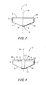
- Fig. 4 is a section view of a permanent magnet according to a second embodiment of this invention.
- Fig. 5 is a section view of a permanent magnet according to a third embodiment of this invention.
- Fig. 6 is a section view of a permanent magnet according to a fourth embodiment of this invention.
- Fig. 7. is a section view of a motor/generator according to a fifth embodiment of this invention.
- a motor 1 according to this invention comprises a rotor 2, a stator 5 arranged on the outside of the rotor 2, and plural permanent magnets 3 embedded in the rotor 2.
- the stator 5 is provided with an identical number of coils 25 to those of the permanent magnets 3, and the stator 5 generates magnetic fluxes by passing a current in these coils 25.
- Plural insertion holes 20 which hold the permanent magnets 3 are formed near the periphery of the rotor 2 housed in the stator 2.
- the insertion holes 20 are arranged so that there is an equal spacing to the adjacent insertion holes 20.
- the insertion holes 20 have a similar shape to those of the permanent magnets 3.
- the insertion holes 20 are formed slightly larger than the size of the permanent magnet 3 so that the magnets 3 can be easily inserted.
- the permanent magnet 3 magnetized by one pole is inserted in the insertion hole 20, and is fixed with an adhesive bond so that it bonds to and fits with the inner side surface 21 of the insertion hole 20 on the side of the rotor core 4.
- the permanent magnet 3 is fixed so that the centerline of its outer side surface and the radial line of the rotor intersect at right angles.
- the permanent magnets 3 generate magnetic fluxes on the periphery and in a direction perpendicular to the outer surface of the rotor 2, interact with the magnetic fluxes generated by the stator 5, and rotate the rotor 2.
- the permanent magnets 3 are disposed alternately so that the magnetization direction and the magnetization direction of the adjacent permanent magnet 3 are opposite each other.
- a clearance 30 prevents contact between the rotating rotor 2 and the stationary stator 5.
- the rotor core 4 which supports the rotor 2 so as to maintain the clearance 30 is fixed to the inner surface of the rotor 2.
- the rotor 2 shown in Fig. 1 comprises eight of the permanent magnets 3, but the number of the permanent magnets 3 is not limited to eight.
- the number of permanent magnets 3 can be two or an even number greater than two.
- the permanent magnet 3 has an outer side surface 6 of a flat plane facing the outer surface of the rotor 2, a inner side surface 12 of a V-shaped plane facing the inner circumference of the rotor 2, a right-hand side surface 7 of a flat plane which extends toward the inner side surface 12 from the right end of the outer side surface 6 in a perpendicular direction to the outer circumferential surface 6, and a left-hand side surface 8 of a flat plane which extends toward the inner side surface 12 from the left end of the outer side surface 6 in a perpendicular direction to the outer side surface 6.
- the surface extending vertically from the centerline of the outer side surface 6 of the permanent magnet 3 toward the inner surface of the rotor 2 is a substantial center plane 16.
- This substantial center plane 16 is parallel to the direction of the magnetic flux generated by the permanent magnet 3.
- the inner side surface 12 of the permanent magnet 3 is formed by a right-hand inner side surface 10 and a left-hand inner side surface 11 which are symmetric with respect to the substantial central plane 16. Both the right-hand inner side surface 10 and the left-hand inner side surface 11 form angles ⁇ with the substantial center plane 16.
- the inner side surface 12 of the permanent magnet 3 is V-shaped surface which projects into the rotor core 4. Therefore, the right-hand inner side surface 10 and left-hand inner side surface 11 respectively form angles ⁇ less than 90 degrees with the substantial center plane 16.
- the inner side surface 21 of the insertion hole 20 is formed in a V-shape which is hollowed in the inner circumferential direction of the rotor 2 corresponding to the shape of the permanent magnet 3.
- the inner side surface 12 of the permanent magnet 3 fits closely to the inner side surface 21 of the insertion hole 20.
- the inner side surface 12 of the permanent magnet 3 By forming the inner side surface 12 of the permanent magnet 3 in the V-shape, the sliding of the permanent magnet 3 is prevented and the permanent magnet 3 can be fixed on the predetermined position. Also, even if the inner side surface 12 of the permanent magnet 3 is V-shaped, the magnetic loss of the rotor 2 can be reduced, and the performance of the motor/generator 1 can be improved.
- the inner side surface 12 of the permanent magnet 3 is flat, and is not V-shaped.
- the rotor 2 then has magnetic losses.
- Another advantage of forming the inner side surface 12 of the permanent magnet 3 in the V-shape is that there is no need to form the inner side surface 12 of the permanent magnet 3 in the arc shape, so manufacture of the permanent magnet 3 becomes easy.
- the permanent magnet 3 is symmetrically separated into a left side permanent magnet 31 and a right side permanent magnet 30 with respect to the substantial center plane 16.
- the insertion hole 20 comprises a beam 17 which partitions the housing space into two chambers 25, 26 in the center so as to accommodate these permanent magnets 30, 31.
- the right-hand chamber 25 of the insertion hole 20 houses the permanent magnet 30 having the right-hand inner side surface 10.
- the left-hand chamber 26 of the insertion hole 20 houses the permanent magnet 31 having the left-hand inner side surface 11.
- a set of these permanent magnets 30, 31 functions as the permanent magnet 3 shown in the first embodiment.
- Dividing the permanent magnet 3 and interposing the beam 17 in the middle of the insertion hole 20 increase the strength of the rotor 2. Also, the permanent magnets 30, 31 can be manufactured economically with high precision.
- the inner side surface 12 of the permanent magnet 3 comprises three planes; the right-hand inner side surface 10, the left-hand inner side surface 11, and a contact plane 14 which connects the substantial center plane 16 side of the right-hand inner side surface 10 and the substantial center plane 16 side of the left-hand inner side surface 11 in parallel with the outer side surface 6.
- the inner side surface 21 of the insertion hole 20 of the rotor 2 is also formed in the similar shape to the inner side surface 12 of the permanent magnet 3.
- the angle ⁇ can be set in the range from 55 degrees to 80 degrees to reduce the magnetic losses without increasing a height L of the inner side surface 12.
- this invention can be applied to the motor 1 having a small width between the inner and outer surface of the rotor 2, and an identical effect that of the first embodiment can be obtained.
- the outer side surface 6 of the permanent magnet 3 is a curved surface parallel to the outer circumference of the rotor 2. Apart from this difference, the remaining parts are identical to those of the first embodiment. Due to this, the magnetic flux generated by the permanent magnet 3 increases.
- the stator 5 of the motor 1 comprises plural of the permanent magnets 3 of this invention, and the rotor 2 comprises plural of coils 25.
- the permanent magnets 3 generates a magnetic field toward the coils 25 of the rotor 2, so the permanent magnets 3 are disposed in the stator 5 to have the inner side surfaces 12 face toward the opposite direction of the rotor 2.
- This invention may be applied not only to: a motor, but also to a generator.
Landscapes
- Engineering & Computer Science (AREA)
- Power Engineering (AREA)
- Permanent Field Magnets Of Synchronous Machinery (AREA)
- Permanent Magnet Type Synchronous Machine (AREA)
Applications Claiming Priority (2)
| Application Number | Priority Date | Filing Date | Title |
|---|---|---|---|
| JP2001231400 | 2001-07-31 | ||
| JP2001231400A JP2003047185A (ja) | 2001-07-31 | 2001-07-31 | 永久磁石式回転電機 |
Publications (2)
| Publication Number | Publication Date |
|---|---|
| EP1282214A2 true EP1282214A2 (fr) | 2003-02-05 |
| EP1282214A3 EP1282214A3 (fr) | 2004-10-20 |
Family
ID=19063459
Family Applications (1)
| Application Number | Title | Priority Date | Filing Date |
|---|---|---|---|
| EP02012834A Withdrawn EP1282214A3 (fr) | 2001-07-31 | 2002-06-10 | Moteur-générateur à aimants permanents |
Country Status (3)
| Country | Link |
|---|---|
| US (1) | US6885122B2 (fr) |
| EP (1) | EP1282214A3 (fr) |
| JP (1) | JP2003047185A (fr) |
Cited By (2)
| Publication number | Priority date | Publication date | Assignee | Title |
|---|---|---|---|---|
| EP1898512A1 (fr) * | 2006-09-07 | 2008-03-12 | Alcatel Lucent | Procédé d'assemblage de paquets de tôles de rotor et dispositifs correspondants |
| CN108336836A (zh) * | 2017-11-22 | 2018-07-27 | 珠海磐磊智能科技有限公司 | 电机 |
Families Citing this family (15)
| Publication number | Priority date | Publication date | Assignee | Title |
|---|---|---|---|---|
| JP4642589B2 (ja) * | 2005-08-09 | 2011-03-02 | 本田技研工業株式会社 | 永久磁石式回転子とその製造方法 |
| US7385328B2 (en) * | 2006-05-23 | 2008-06-10 | Reliance Electric Technologies, Llc | Cogging reduction in permanent magnet machines |
| US7898137B2 (en) * | 2006-08-30 | 2011-03-01 | Shin-Etsu Chemical Co., Ltd. | Permanent magnet and permanent magnet rotating machine |
| JP2010022088A (ja) * | 2008-07-08 | 2010-01-28 | Kokusan Denki Co Ltd | 磁石回転型回転電機 |
| US20100085787A1 (en) * | 2008-10-03 | 2010-04-08 | Ajit Wasant Kane | System and method for powering a hybrid electric vehicle |
| JP4685946B2 (ja) * | 2009-02-18 | 2011-05-18 | 三菱電機株式会社 | 永久磁石型回転電機の回転子およびその製造方法 |
| US20110101817A1 (en) * | 2009-11-05 | 2011-05-05 | Gm Global Technology Operations, Inc. | Variable geometry electric machine |
| US8634217B2 (en) * | 2010-09-30 | 2014-01-21 | Intersil Americas Inc. | System and method for converting an AC input voltage to a regulated DC output voltage using a Z-type converter with rectified switches |
| JP5418467B2 (ja) * | 2010-11-02 | 2014-02-19 | 株式会社安川電機 | 回転電機 |
| JP5240592B2 (ja) | 2011-07-08 | 2013-07-17 | 株式会社安川電機 | 回転電機 |
| FR2982093B1 (fr) * | 2011-10-27 | 2017-11-03 | Valeo Equip Electr Moteur | Rotor de machine electrique tournante et machine electrique tournante comprenant un rotor |
| KR101940755B1 (ko) * | 2012-01-16 | 2019-01-21 | 삼성전자 주식회사 | 회전자 및 이를 포함하는 전동기 |
| CN107742966B (zh) * | 2017-10-28 | 2020-10-23 | 珠海磐磊智能科技有限公司 | 电机 |
| JP2020096484A (ja) * | 2018-12-14 | 2020-06-18 | Tdk株式会社 | 永久磁石および回転電機 |
| JP7331356B2 (ja) * | 2018-12-14 | 2023-08-23 | Tdk株式会社 | 永久磁石および回転電機 |
Family Cites Families (23)
| Publication number | Priority date | Publication date | Assignee | Title |
|---|---|---|---|---|
| US3840763A (en) * | 1973-07-09 | 1974-10-08 | Gen Electric | Low flux density permanent magnet field configuration |
| US4476408A (en) * | 1979-05-23 | 1984-10-09 | General Electric Company | High efficiency, low cost permanent magnet AC machine |
| US4327302A (en) * | 1979-09-21 | 1982-04-27 | General Electric Company | Electronically commutated motor, stationary and rotatable assemblies therefore, and lamination |
| US5191256A (en) * | 1989-12-15 | 1993-03-02 | American Motion Systems | Interior magnet rotary machine |
| JPH05176487A (ja) * | 1991-10-24 | 1993-07-13 | Toshiba Corp | 永久磁石形モータ |
| JP3424765B2 (ja) * | 1994-03-11 | 2003-07-07 | 株式会社安川電機 | 永久磁石形同期回転電機 |
| JPH0823664A (ja) * | 1994-05-02 | 1996-01-23 | Aisin Aw Co Ltd | モータ |
| US5811904A (en) * | 1996-03-21 | 1998-09-22 | Hitachi, Ltd. | Permanent magnet dynamo electric machine |
| JP3072504B2 (ja) * | 1996-07-18 | 2000-07-31 | アイチ−エマソン電機株式会社 | 電動機の回転子 |
| US6133662A (en) * | 1996-09-13 | 2000-10-17 | Hitachi, Ltd. | Permanent magnet dynamoelectric rotating machine and electric vehicle equipped with the same |
| JP3509508B2 (ja) * | 1997-02-21 | 2004-03-22 | アイシン・エィ・ダブリュ株式会社 | 永久磁石式同期モータ |
| KR100252393B1 (ko) * | 1997-05-13 | 2000-04-15 | 윤종용 | 영구자석매립형회전자구조 |
| JP3906882B2 (ja) * | 1997-10-24 | 2007-04-18 | 株式会社富士通ゼネラル | 永久磁石電動機 |
| KR100263445B1 (ko) * | 1997-11-13 | 2000-08-01 | 윤종용 | 브러시리스 dc모터용 회전자 |
| KR20000009230A (ko) * | 1998-07-22 | 2000-02-15 | 윤종용 | 브리시리스 직류 전동기 |
| JP3601757B2 (ja) * | 1998-08-03 | 2004-12-15 | オークマ株式会社 | 永久磁石モータ |
| JP3487191B2 (ja) | 1998-09-01 | 2004-01-13 | トヨタ自動車株式会社 | 電動式パワーステアリング装置 |
| US6340857B2 (en) * | 1998-12-25 | 2002-01-22 | Matsushita Electric Industrial Co., Ltd. | Motor having a rotor with interior split-permanent-magnet |
| JP2000245085A (ja) * | 1998-12-25 | 2000-09-08 | Matsushita Electric Ind Co Ltd | モータ |
| JP2000324736A (ja) * | 1999-05-12 | 2000-11-24 | Mitsubishi Electric Corp | 永久磁石型モータ |
| JP2000333391A (ja) * | 1999-05-19 | 2000-11-30 | Hitachi Ltd | 永久磁石式回転電機 |
| JP2001314052A (ja) * | 2000-02-25 | 2001-11-09 | Nissan Motor Co Ltd | 同期電動機のロータ構造 |
| DE60141308D1 (de) * | 2000-03-31 | 2010-04-01 | Sanyo Electric Co | Synchronmotor mit internem Dauermagnet |
-
2001
- 2001-07-31 JP JP2001231400A patent/JP2003047185A/ja active Pending
-
2002
- 2002-06-10 EP EP02012834A patent/EP1282214A3/fr not_active Withdrawn
- 2002-07-24 US US10/200,948 patent/US6885122B2/en not_active Expired - Fee Related
Cited By (3)
| Publication number | Priority date | Publication date | Assignee | Title |
|---|---|---|---|---|
| EP1898512A1 (fr) * | 2006-09-07 | 2008-03-12 | Alcatel Lucent | Procédé d'assemblage de paquets de tôles de rotor et dispositifs correspondants |
| CN108336836A (zh) * | 2017-11-22 | 2018-07-27 | 珠海磐磊智能科技有限公司 | 电机 |
| CN108336836B (zh) * | 2017-11-22 | 2020-07-28 | 珠海磐磊智能科技有限公司 | 电机 |
Also Published As
| Publication number | Publication date |
|---|---|
| US6885122B2 (en) | 2005-04-26 |
| US20030025414A1 (en) | 2003-02-06 |
| JP2003047185A (ja) | 2003-02-14 |
| EP1282214A3 (fr) | 2004-10-20 |
Similar Documents
| Publication | Publication Date | Title |
|---|---|---|
| EP1282214A2 (fr) | Moteur-générateur à aimants permanents | |
| US8405270B2 (en) | Permanent magnet buried type electric motor | |
| EP1610444A1 (fr) | Moteur électrique synchrone | |
| US20120091845A1 (en) | Brushless motor | |
| US7994676B2 (en) | Reluctance motor rotor and reluctance motor equipped with the same | |
| US8760026B2 (en) | Rotor with V-shaped permanent magnet arrangement, rotating electric machine, vehicle, elevator, fluid machine, and processing machine | |
| JP2014039475A (ja) | Pmシンクロナスモータ | |
| US20200303979A1 (en) | Rotor and electrical machine | |
| US12261485B2 (en) | Rotor with permanent magnets having different coercive forces | |
| US7405504B2 (en) | Rotor for rotary electric machine | |
| CN113224880A (zh) | 马达总成及马达转子 | |
| US20220060070A1 (en) | Rotating electric machine | |
| JP2000278896A (ja) | 電動機のロータ | |
| EP4027491A1 (fr) | Rotor pour machine électrique tournante | |
| US11909266B2 (en) | Rotor, and rotary electric machine provided with same | |
| KR20110058057A (ko) | 영구자석형 전동기 | |
| US11611251B2 (en) | Motor having asymmetric rotor core | |
| US20020050760A1 (en) | Brushless motor | |
| US11159067B2 (en) | Rotor and motor | |
| US20230179039A1 (en) | Permanent magnet machine | |
| US12249867B2 (en) | Rotary electrical device | |
| JP2619572B2 (ja) | ラジアルタイプのロータ構造 | |
| US20250030287A1 (en) | A rotor with embedded magnets for a permanent magnet motor | |
| EP4300774B1 (fr) | Machine électrique tournante | |
| CN212486223U (zh) | 转子及马达 |
Legal Events
| Date | Code | Title | Description |
|---|---|---|---|
| PUAI | Public reference made under article 153(3) epc to a published international application that has entered the european phase |
Free format text: ORIGINAL CODE: 0009012 |
|
| 17P | Request for examination filed |
Effective date: 20020610 |
|
| AK | Designated contracting states |
Designated state(s): AT BE CH CY DE DK ES FI FR GB GR IE IT LI LU MC NL PT SE TR |
|
| AX | Request for extension of the european patent |
Extension state: AL LT LV MK RO SI |
|
| PUAL | Search report despatched |
Free format text: ORIGINAL CODE: 0009013 |
|
| AK | Designated contracting states |
Kind code of ref document: A3 Designated state(s): AT BE CH CY DE DK ES FI FR GB GR IE IT LI LU MC NL PT SE TR |
|
| AX | Request for extension of the european patent |
Extension state: AL LT LV MK RO SI |
|
| STAA | Information on the status of an ep patent application or granted ep patent |
Free format text: STATUS: THE APPLICATION HAS BEEN WITHDRAWN |
|
| AKX | Designation fees paid |
Designated state(s): DE FR GB |
|
| 17Q | First examination report despatched |
Effective date: 20050606 |
|
| 18W | Application withdrawn |
Effective date: 20050601 |