EP1282500B1 - Procede et dispositif de fabrication d'une piece moulee a partir d'un compose plastique/metallique et utilisation dudit dispositif - Google Patents
Procede et dispositif de fabrication d'une piece moulee a partir d'un compose plastique/metallique et utilisation dudit dispositif Download PDFInfo
- Publication number
- EP1282500B1 EP1282500B1 EP01960219A EP01960219A EP1282500B1 EP 1282500 B1 EP1282500 B1 EP 1282500B1 EP 01960219 A EP01960219 A EP 01960219A EP 01960219 A EP01960219 A EP 01960219A EP 1282500 B1 EP1282500 B1 EP 1282500B1
- Authority
- EP
- European Patent Office
- Prior art keywords
- semi
- finished product
- polymer melt
- injection moulding
- form tool
- Prior art date
- Legal status (The legal status is an assumption and is not a legal conclusion. Google has not performed a legal analysis and makes no representation as to the accuracy of the status listed.)
- Expired - Lifetime
Links
Images



Classifications
-
- B—PERFORMING OPERATIONS; TRANSPORTING
- B21—MECHANICAL METAL-WORKING WITHOUT ESSENTIALLY REMOVING MATERIAL; PUNCHING METAL
- B21D—WORKING OR PROCESSING OF SHEET METAL OR METAL TUBES, RODS OR PROFILES WITHOUT ESSENTIALLY REMOVING MATERIAL; PUNCHING METAL
- B21D26/00—Shaping without cutting otherwise than using rigid devices or tools or yieldable or resilient pads, i.e. applying fluid pressure or magnetic forces
- B21D26/02—Shaping without cutting otherwise than using rigid devices or tools or yieldable or resilient pads, i.e. applying fluid pressure or magnetic forces by applying fluid pressure
- B21D26/033—Deforming tubular bodies
- B21D26/041—Means for controlling fluid parameters, e.g. pressure or temperature
-
- B—PERFORMING OPERATIONS; TRANSPORTING
- B21—MECHANICAL METAL-WORKING WITHOUT ESSENTIALLY REMOVING MATERIAL; PUNCHING METAL
- B21D—WORKING OR PROCESSING OF SHEET METAL OR METAL TUBES, RODS OR PROFILES WITHOUT ESSENTIALLY REMOVING MATERIAL; PUNCHING METAL
- B21D26/00—Shaping without cutting otherwise than using rigid devices or tools or yieldable or resilient pads, i.e. applying fluid pressure or magnetic forces
- B21D26/02—Shaping without cutting otherwise than using rigid devices or tools or yieldable or resilient pads, i.e. applying fluid pressure or magnetic forces by applying fluid pressure
- B21D26/033—Deforming tubular bodies
- B21D26/037—Forming branched tubes
-
- B—PERFORMING OPERATIONS; TRANSPORTING
- B29—WORKING OF PLASTICS; WORKING OF SUBSTANCES IN A PLASTIC STATE IN GENERAL
- B29C—SHAPING OR JOINING OF PLASTICS; SHAPING OF MATERIAL IN A PLASTIC STATE, NOT OTHERWISE PROVIDED FOR; AFTER-TREATMENT OF THE SHAPED PRODUCTS, e.g. REPAIRING
- B29C45/00—Injection moulding, i.e. forcing the required volume of moulding material through a nozzle into a closed mould; Apparatus therefor
- B29C45/14—Injection moulding, i.e. forcing the required volume of moulding material through a nozzle into a closed mould; Apparatus therefor incorporating preformed parts or layers, e.g. injection moulding around inserts or for coating articles
- B29C45/1418—Injection moulding, i.e. forcing the required volume of moulding material through a nozzle into a closed mould; Apparatus therefor incorporating preformed parts or layers, e.g. injection moulding around inserts or for coating articles the inserts being deformed or preformed, e.g. by the injection pressure
-
- B—PERFORMING OPERATIONS; TRANSPORTING
- B29—WORKING OF PLASTICS; WORKING OF SUBSTANCES IN A PLASTIC STATE IN GENERAL
- B29C—SHAPING OR JOINING OF PLASTICS; SHAPING OF MATERIAL IN A PLASTIC STATE, NOT OTHERWISE PROVIDED FOR; AFTER-TREATMENT OF THE SHAPED PRODUCTS, e.g. REPAIRING
- B29C45/00—Injection moulding, i.e. forcing the required volume of moulding material through a nozzle into a closed mould; Apparatus therefor
- B29C45/17—Component parts, details or accessories; Auxiliary operations
- B29C45/1703—Introducing an auxiliary fluid into the mould
- B29C45/1704—Introducing an auxiliary fluid into the mould the fluid being introduced into the interior of the injected material which is still in a molten state, e.g. for producing hollow articles
- B29C45/1705—Introducing an auxiliary fluid into the mould the fluid being introduced into the interior of the injected material which is still in a molten state, e.g. for producing hollow articles using movable mould parts
-
- B—PERFORMING OPERATIONS; TRANSPORTING
- B29—WORKING OF PLASTICS; WORKING OF SUBSTANCES IN A PLASTIC STATE IN GENERAL
- B29C—SHAPING OR JOINING OF PLASTICS; SHAPING OF MATERIAL IN A PLASTIC STATE, NOT OTHERWISE PROVIDED FOR; AFTER-TREATMENT OF THE SHAPED PRODUCTS, e.g. REPAIRING
- B29C45/00—Injection moulding, i.e. forcing the required volume of moulding material through a nozzle into a closed mould; Apparatus therefor
- B29C45/17—Component parts, details or accessories; Auxiliary operations
- B29C45/1703—Introducing an auxiliary fluid into the mould
- B29C45/1704—Introducing an auxiliary fluid into the mould the fluid being introduced into the interior of the injected material which is still in a molten state, e.g. for producing hollow articles
- B29C45/1711—Introducing an auxiliary fluid into the mould the fluid being introduced into the interior of the injected material which is still in a molten state, e.g. for producing hollow articles and removing excess material from the mould cavity by the introduced fluid, e.g. to an overflow cavity
-
- B—PERFORMING OPERATIONS; TRANSPORTING
- B29—WORKING OF PLASTICS; WORKING OF SUBSTANCES IN A PLASTIC STATE IN GENERAL
- B29C—SHAPING OR JOINING OF PLASTICS; SHAPING OF MATERIAL IN A PLASTIC STATE, NOT OTHERWISE PROVIDED FOR; AFTER-TREATMENT OF THE SHAPED PRODUCTS, e.g. REPAIRING
- B29C45/00—Injection moulding, i.e. forcing the required volume of moulding material through a nozzle into a closed mould; Apparatus therefor
- B29C45/14—Injection moulding, i.e. forcing the required volume of moulding material through a nozzle into a closed mould; Apparatus therefor incorporating preformed parts or layers, e.g. injection moulding around inserts or for coating articles
- B29C45/14336—Coating a portion of the article, e.g. the edge of the article
- B29C45/14344—Moulding in or through a hole in the article, e.g. outsert moulding
- B29C2045/1436—Moulding in or through a hole in the article, e.g. outsert moulding coating hollow articles having holes passing through the wall
-
- B—PERFORMING OPERATIONS; TRANSPORTING
- B29—WORKING OF PLASTICS; WORKING OF SUBSTANCES IN A PLASTIC STATE IN GENERAL
- B29C—SHAPING OR JOINING OF PLASTICS; SHAPING OF MATERIAL IN A PLASTIC STATE, NOT OTHERWISE PROVIDED FOR; AFTER-TREATMENT OF THE SHAPED PRODUCTS, e.g. REPAIRING
- B29C45/00—Injection moulding, i.e. forcing the required volume of moulding material through a nozzle into a closed mould; Apparatus therefor
- B29C45/17—Component parts, details or accessories; Auxiliary operations
- B29C45/1703—Introducing an auxiliary fluid into the mould
- B29C45/1704—Introducing an auxiliary fluid into the mould the fluid being introduced into the interior of the injected material which is still in a molten state, e.g. for producing hollow articles
- B29C45/1706—Introducing an auxiliary fluid into the mould the fluid being introduced into the interior of the injected material which is still in a molten state, e.g. for producing hollow articles using particular fluids or fluid generating substances
- B29C2045/1707—Introducing an auxiliary fluid into the mould the fluid being introduced into the interior of the injected material which is still in a molten state, e.g. for producing hollow articles using particular fluids or fluid generating substances using a liquid, e.g. water
-
- B—PERFORMING OPERATIONS; TRANSPORTING
- B29—WORKING OF PLASTICS; WORKING OF SUBSTANCES IN A PLASTIC STATE IN GENERAL
- B29C—SHAPING OR JOINING OF PLASTICS; SHAPING OF MATERIAL IN A PLASTIC STATE, NOT OTHERWISE PROVIDED FOR; AFTER-TREATMENT OF THE SHAPED PRODUCTS, e.g. REPAIRING
- B29C45/00—Injection moulding, i.e. forcing the required volume of moulding material through a nozzle into a closed mould; Apparatus therefor
- B29C45/17—Component parts, details or accessories; Auxiliary operations
- B29C45/1703—Introducing an auxiliary fluid into the mould
- B29C45/1704—Introducing an auxiliary fluid into the mould the fluid being introduced into the interior of the injected material which is still in a molten state, e.g. for producing hollow articles
- B29C45/1706—Introducing an auxiliary fluid into the mould the fluid being introduced into the interior of the injected material which is still in a molten state, e.g. for producing hollow articles using particular fluids or fluid generating substances
- B29C2045/171—Introducing an auxiliary fluid into the mould the fluid being introduced into the interior of the injected material which is still in a molten state, e.g. for producing hollow articles using particular fluids or fluid generating substances using an evaporating substance
-
- B—PERFORMING OPERATIONS; TRANSPORTING
- B29—WORKING OF PLASTICS; WORKING OF SUBSTANCES IN A PLASTIC STATE IN GENERAL
- B29C—SHAPING OR JOINING OF PLASTICS; SHAPING OF MATERIAL IN A PLASTIC STATE, NOT OTHERWISE PROVIDED FOR; AFTER-TREATMENT OF THE SHAPED PRODUCTS, e.g. REPAIRING
- B29C45/00—Injection moulding, i.e. forcing the required volume of moulding material through a nozzle into a closed mould; Apparatus therefor
- B29C45/17—Component parts, details or accessories; Auxiliary operations
- B29C45/1703—Introducing an auxiliary fluid into the mould
- B29C45/1704—Introducing an auxiliary fluid into the mould the fluid being introduced into the interior of the injected material which is still in a molten state, e.g. for producing hollow articles
- B29C45/1711—Introducing an auxiliary fluid into the mould the fluid being introduced into the interior of the injected material which is still in a molten state, e.g. for producing hollow articles and removing excess material from the mould cavity by the introduced fluid, e.g. to an overflow cavity
- B29C2045/1712—Introducing an auxiliary fluid into the mould the fluid being introduced into the interior of the injected material which is still in a molten state, e.g. for producing hollow articles and removing excess material from the mould cavity by the introduced fluid, e.g. to an overflow cavity plastic material flowing back into the injection unit
-
- B—PERFORMING OPERATIONS; TRANSPORTING
- B29—WORKING OF PLASTICS; WORKING OF SUBSTANCES IN A PLASTIC STATE IN GENERAL
- B29C—SHAPING OR JOINING OF PLASTICS; SHAPING OF MATERIAL IN A PLASTIC STATE, NOT OTHERWISE PROVIDED FOR; AFTER-TREATMENT OF THE SHAPED PRODUCTS, e.g. REPAIRING
- B29C45/00—Injection moulding, i.e. forcing the required volume of moulding material through a nozzle into a closed mould; Apparatus therefor
- B29C45/17—Component parts, details or accessories; Auxiliary operations
- B29C45/1703—Introducing an auxiliary fluid into the mould
- B29C45/1704—Introducing an auxiliary fluid into the mould the fluid being introduced into the interior of the injected material which is still in a molten state, e.g. for producing hollow articles
- B29C2045/1724—Introducing an auxiliary fluid into the mould the fluid being introduced into the interior of the injected material which is still in a molten state, e.g. for producing hollow articles hollows used as conduits
-
- B—PERFORMING OPERATIONS; TRANSPORTING
- B29—WORKING OF PLASTICS; WORKING OF SUBSTANCES IN A PLASTIC STATE IN GENERAL
- B29K—INDEXING SCHEME ASSOCIATED WITH SUBCLASSES B29B, B29C OR B29D, RELATING TO MOULDING MATERIALS OR TO MATERIALS FOR MOULDS, REINFORCEMENTS, FILLERS OR PREFORMED PARTS, e.g. INSERTS
- B29K2705/00—Use of metals, their alloys or their compounds, for preformed parts, e.g. for inserts
Definitions
- the invention relates to a method for hydroforming from tubular semi-finished metal products to the molded part, by turning the semi-finished product into an at least two-part Molding tool with one corresponding to the outer contour of the molded part Molding space inserted, with the exception of the molding tool the open end of the semi-finished product is closed, the semi-finished product is sealed pressure-tight on its open end faces and from at least one end face with one Injection molding into the semi-finished polymer melt high pressure is molded into the mold space. Furthermore concerns the invention a device for hydroforming of tubular semi-finished metal and use such a device.
- the source material is generally a tubular semi-finished product with any cross-section and any cross-sectional shape, which is formed into a hollow molded part.
- the tubular Semi-finished product is placed in a two-part mold, the shape space of the desired outer contour of the Molding corresponds. After closing the tool, it will tubular semi-finished products sealed on both faces and a fluid under high pressure via at least one end face abandoned and thereby "inflated" the semi-finished product until it has taken the final shape.
- This process can be used to make relatively complicated moldings manufacture that used to be only by deep drawing or Pressing two molded part halves or several molded parts and subsequent assembly of the same could be produced. Exhaust systems and their parts, hollow frames or frame parts, etc. called. The procedure is the same for others technical components used, provided they are in the appropriate Number of pieces to be manufactured.
- a disadvantage of the known method is that it is used Oil / water emulsion has certain environmental risks brings. In the workplace of such a forming plant falls also always the emulsion on what with appropriate Cleaning work is connected. Furthermore, the emulsion are continuously supplemented or even replaced. Finally acts the process is cold forming since the Forming fluid usually with ambient temperature or little is used above and a temperature in the range of the boiling point of water is prohibited.
- the invention has for its object the known method and to further develop the known device, that with a low plastic requirement diverse design of molded parts from a metal / plastic composite is possible.
- This task is done from a procedural point of view solved that the polymer melt after forming the Semi-finished product to the molded part by means of a pressurized fluid inert to the polymer melt Formation of a polymer inner layer on the molded part at least is partially displaced from the molded part.
- a polymer melt used in the method according to the invention can have a temperature between 150 and 350 ° C. With this forming fluid, the forming temperature becomes corresponding raised so that - as with thermoforming - the forming forces and thus the active media pressure is reduced accordingly can be.
- hydroforming is used according to the invention with one in plastics technology known process technology, namely injection molding, so that from a procedural point of view none new technical concepts have to be developed.
- the semi-finished product from a less high quality Metal can exist. It can also be a semi-finished product with less Wall thickness used and on a very thin end wall thickness be reshaped because the inner layer for a provides additional stabilization. So you can on this How to produce lightweight components with thin metal skin.
- Essential is in this process that the forming fluid, namely the polymer melt, directly into a technical functional part, namely the coating, implemented becomes. In particular, no fluid is lost, such as there is also no disposal as the excess polymer melt can be reused.
- high quality plastic injection molded parts Plastic recyclates are processed. Compared to the conventional Injection molding can shorten the cycle time because the molded part can be demolded earlier.
- the polymer melt becomes immediately after the semi-finished product is formed completely blown out, becomes a metallic molding preserved with thin plastic skin, however, it is delayed and only partially blown out, one gets one Composite molded part made of metal with a thicker inner coating.
- the wall thickness of the inner coating can be controlled by external cooling of the molded part in the mold and / or by control control the residence time of the polymer until blowing out.
- the blown-out polymer can be reused.
- the polymer melt is preferably blown out by means of Gas or water, which at the same time to cool the im Molded part for the inner coating of remaining polymer can serve.
- the molding tool is heated to cool the polymer melt too quickly prevent and take advantage of thermoforming to use.
- the heating temperature is controlled so that that the semi-finished product does not have a higher temperature than that Melting temperature of the polymer melt assumes.
- Such one Heating is particularly recommended at the beginning of a production cycle, while with increasing operating time on Set the mold to elevated temperatures anyway. Nevertheless, due to the metal shell is an early one Demoulding possible.
- the polymer melt is preferably injected by means of a conventional injection molding unit, the injection nozzle of the injection molding unit the open Front side of the semi-finished product can seal immediately.
- the injection molding unit tracked according to the progress of the semi-finished product.
- the method according to the invention can be modified accordingly be that the tubular semi-finished product with at least one Breakthrough is provided in the mold by a Slider is closed, and that after reshaping the Part of the semi-finished product when displacing the polymer melt by retracting the slider into one of them limited mold space is displaced in the mold.
- part of the melt is released displaced the outside of the metallic molding and forms a part of the outer contour made of plastic of the molded part. So the plastic penetrates the metallic outer skin.
- metallic Technical functional parts made of plastic on the outside be formed, e.g. Ribs, fasteners for that Molding and the like.
- the openings can be on the semi-finished product the insertion in the mold or in the mold generated by machining with chip extraction.
- tubular Semi-finished products on at least one end face at least is partially closed and in the area of the closure at least one opening is provided in the mold is closed by a slide, and that after the reshaping of the semi-finished product when displacing the polymer melt part of it by retracting the slide into a mold space of the mold limited by this is ousted.
- the of the molded part from the metal / plastic composite additional Form plastic contours, e.g. parts of Plug connections, force-transmitting drivers, parts of a Plastic connection for the molded part or the like.
- the method according to the invention can do this be modified that the tubular semi-finished product at least one end is closed by a controllable nozzle is in the closed position during forming is held, and that the nozzle after reshaping the Semi-finished product opened and the polymer melt when displaced from the semi-finished product through the nozzle into outside the mold arranged mold spaces for the formation of injection molded parts is ousted.
- the one displaced from the molded part can be Polymer melt immediately to further injection molded parts Process from plastic. So the polymer melt is on the one hand tools for hydroforming, on the other Material for forming molded parts.
- the invention is based on a device for production a molded part made of a metal / plastic composite by hydroforming tubular semi-finished products Metal by means of a fluid to the molded part consisting of an at least two-part mold with one of the The outer contour of the molded part corresponding to the molded space, the inserted Closing semi-finished products on its open end faces Seals and at least one on one end face connectable, pressing a polymer melt into the semi-finished product Injection molding unit.
- Such a device is characterized according to the invention by an open end face of the tubular semi-finished product, if applicable, the one opposite the injection molding unit Front side, connectable pressure unit for generation an internal pressure to displace the polymer melt to the inner wall of the semifinished product during forming metallic, hollow molded parts with a plastic inner coating make:
- the injection molding unit a sealing the open end of the semi-finished product Injection mouthpiece and is the injection molding unit preferably movable to seal with the Injection nozzle of the movement of the open face of the Semi-finished product to follow during forming.
- the mold can be heated to the in The polymer melt pressed into the semi-finished product does not cool down too quickly and to support the hot forming process.
- the blown-out polymer melt can enter the injection molding unit to be led back.
- Injection molding units are available for this with sliding extruder screw. To the injection of the polymer melt into the semi-finished product and the extruder screw can transform it into the final molded part withdrawn and the blown out polymer melt pressed back into the space thus created become.
- the Molding tool outside the area occupied by the semi-finished product one of the spray tip in the process of Injection mold exposed mold cavity for receiving the has blown out polymer melt.
- this is after the forming Injection nozzle retracted and thereby a mold cavity exposed in which the polymer melt are blown out can.
- the polymer melt can or the polymer which may have solidified again be fed back to the injection molding unit.
- the mold at least one closed by a slide has additional molding space with a opening provided in the tubular semi-finished product corresponds and this closes, and that the slide after the shaping of the semi-finished product the additional molding space for releases access to the polymer melt.
- the device is designed so that the mold at least one interacting with the end face of the semi-finished product Has slide, which with an opening the partially closed end face of the semi-finished product interacts and closes an additional molding space, and that the slide after forming the semi-finished product the additional Molding space for access to the polymer melt releases.
- This variant can also be used on the front of the molded part additional plastic contours are formed.
- one of the associated partially closed end wall of the semi-finished product Nozzle is arranged, to which further sprue distributors Mold spaces are connected, and that the nozzle after forming of the semi-finished product for the entry of the displaced polymer melt in the other mold spaces in the open position is feasible, which is previously the work tool serving polymer melt completely to form the molded part and other plastic fittings can be used.
- Another use of the device is in manufacture of molded parts made of metal with an inner coating made of plastic and the molding projecting outwards Plastic contours. Furthermore, the device for the production of internally coated molded parts made of metal and any other separate injection molded parts.
- the molded parts produced according to the invention can be used as constructive components, especially lightweight components with acoustic and / or thermal insulation properties, as media-carrying parts with simultaneous wear protection in vehicle construction, in space travel, as well as in heating and use sanitary facilities. You can also contact on the outside plastic molding for diverse have technical functions.
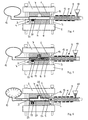
- the molding unit according to FIGS. 1 to 9 has a table 1 serving as a platen 2 crosshead and the compressive forces primarily receiving columns 3, which are not in one machine foundation shown. Furthermore, the Molding unit in the illustrated embodiments two-part molding tool 4, which consists of a with the table 1 connected lower tool 5 and one with the platen 2 connected upper tool 6 exists. By procedure the platen 2 with the upper tool 6 can Open and close mold 4. Lower tool 5 and Upper tool 6 complete a total of 7 Molding space, the inner contour of the outer contour of the to be generated Molding corresponds.
- a conventional injection molding unit is also part of the molding unit 9, in particular a commercially available injection molding machine. It has a feed hopper 10 and two parallel ones Extruder screws 11 on in a heated housing 12 revolve and can be axially displaceable.
- the Housing ends in an injection nozzle 13 through which the via the feed hopper 10, for example as granules abandoned polymer expressed in the form of a melt becomes.
- the injection molding unit 9 is in the direction of the double arrow 14 movable and can consequently with its spray nozzle 13 to the open one on the right in the drawing Started face of the tubular semi-finished product 8 and be pressed tightly.
- a pressure unit can be sealingly connected, such as from injection molding hollow injection molded parts is known and preferably with gas pressure is working.
- the polymer melt via the injection molding unit 9 introduced.
- the semi-finished product is molded into the mold space 7, the polymer melt at least its heat content partially gives off to the semi-finished product, so it is heated and solidified even on the relatively cold semi-finished product and one Inner layer forms, while the core remains plastic (Fig.2). If the semifinished product 8 shortens during forming, the injection molding unit is moved to the seal to maintain on the injection side.
- the printing unit is used 15 the still molten or plastic core is blown out, as shown in Fig.3.
- the extruder screw 11, as a comparison of Fig. 2 and 3 shows to be withdrawn axially, so that in the extruder housing 12 a free space 18 is created, which is the excess Melt resumes. Instead, the excess Melt even after the spray nozzle or the entire injection molding unit by means of the internal gas pressure unit via sprue channels in additional mold cavities, that are outside the mold are transferred.
- Figure 4 to 6 differs differs from that of Figures 1 to 3 only in that the tubular Semi-finished product 8 any opening 21 on its circumference Cross-section, which preferably before Inserting into the mold 4 has been made.
- a Slider On the corresponding position of the mold 4 is a Slider arranged in the lower tool 5 approximately perpendicular is guided to the axis of the tubular semi-finished product.
- the Slider 22 engages in the opening 21 and closes this compared to the interior of the semi-finished product (Fig. 4 and 5).
- the slide 22 becomes the lower tool 5 retracted and then releases a mold space 23 in the the polymer melt penetrates. It becomes one this way Molding 24 with a metal shell 25 and a plastic inner coating 26 received, the outside a molding Has 27 made of plastic, the material with the inner coating 26 is connected.
- FIG. 7 to 9 The structure and operation of the in Fig. 7 to 9 The embodiments shown differ from that shown in FIG. 1 to 3 only in that the tubular semifinished product 8 its end face opposite the injection molding unit 9 is closed by a wall 28, which is only an opening for connecting the printing unit 15 and has an opening 29 above it before insertion of the semifinished product 8 has been generated in the mold 4 is.
- the opening 29 is in the mold 4 by one Closed slide 30, which is guided in the upper tool 6 (Fig.7).
- the slide remains when the polymer melt is injected by means of the injection unit 9 in his Closed position.
- the slide 30 is withdrawn and releases a mold space 31 into which the polymer melt penetrates.
- the finished molded part 32 consists of a Metal jacket 33 with a plastic inner coating 34.
- the metal jacket 33 is on the end wall 28 in the area the opening 29 is surmounted by a plastic molding 35, the material coating with the inner coating of the molded part 32 connected is.
- FIG. 10 shows a perspective partial view of a molded part, as is the case according to the method according to FIGS. 4 to 6 can be manufactured. It has a hollow, tubular shape Base body 36 made of a metal jacket 37 and one Plastic inner coating 38 and on the outside of the Sheath 37 several parallel ribs 39, which from the Plastic of the inner coating 38 consist and with this via corresponding slot-shaped openings in the metal jacket 37 are connected.
- Fig. 11 shows a side view a), top view b) and front view c) a hollow Molding 40 with a tubular metal jacket 41 and one Inner coating 42.
- the metal jacket 41 has approximately openings 43 arranged diametrically, through which the plastic mass of the inner coating 42 after is penetrated outside and there formations 44 that for example to attach the molded part to others Serve components and at the same time the molded part electrically and thermally insulate.
- tubular molding 45 a metal jacket 46 and a Plastic inner coating 47 and a projecting front Profile 48 made of plastic on this one Case designed as a kind of claw or plug coupling is.
- This molded part can be produced by a process be, as described with reference to Figures 7 to 9 has been.
Landscapes
- Engineering & Computer Science (AREA)
- Mechanical Engineering (AREA)
- Manufacturing & Machinery (AREA)
- Physics & Mathematics (AREA)
- Fluid Mechanics (AREA)
- Injection Moulding Of Plastics Or The Like (AREA)
- Moulds For Moulding Plastics Or The Like (AREA)
- Casting Or Compression Moulding Of Plastics Or The Like (AREA)
- Laminated Bodies (AREA)
- Encapsulation Of And Coatings For Semiconductor Or Solid State Devices (AREA)
- Shaping Metal By Deep-Drawing, Or The Like (AREA)
Claims (29)
- Procédé de fabrication d'une pièce moulée à partir d'un composé métal/matière plastique par transformation à haute pression intérieure d'un demi-produit tubulaire en métal pour obtenir une pièce moulée, le demi-produit étant inséré dans un outil de moulage au moins en deux parties présentant un espace de moulage correspondant au contour extérieur de la pièce moulée, l'outil de moulage étant fermé à l'exception des faces frontales du demi-produit ouvertes, le demi-produit étant étanche à la pression au niveau de ses faces frontales et moulé sous haute pression dans l'espace de moulage depuis au moins une face frontale par une masse fondue de polymère pressée par injection dans le demi-produit,
caractérisé en ce que
la masse fondue de polymère, après la transformation du demi-produit en pièce moulée, est du moins partiellement déplacée hors de la pièce moulée au moyen d'un fluide amené sous pression inerte par rapport à la masse fondue de polymère en formant une couche intérieure de polymère sur la pièce moulée. - Procédé selon la revendication 1,
caractérisé en ce que
le fluide est amené selon la technique de pression intérieure de gaz ou d'eau. - Procédé selon l'une quelconque des revendications 1 ou 2,
caractérisé en ce que
la pièce moulée est refroidie à une température inférieure à la température de fusion du polymère, et la pièce moulée est retirée de l'outil de moulage. - Procédé selon l'une quelconque des revendications 1 à 3,
caractérisé en ce que
la masse fondue de polymère est soufflée hors de la pièce moulée au moyen d'un fluide. - Procédé selon la revendication 4,
caractérisé en ce que
la masse fondue de polymère est soufflée au moyen de gaz ou d'eau. - Procédé selon l'une quelconque des revendications 1 à 5,
caractérisé en ce que
l'outil de moulage est chauffé. - Procédé selon l'une quelconque des revendications 1 à 6,
caractérisé en ce que
l'injection de la masse fondue de polymère est effectuée au moyen d'un dispositif de coulée par injection conventionnel. - Procédé selon la revendication 7,
caractérisé en ce que
la face frontale ouverte du demi-produit est rendue étanche au moyen de la filière du dispositif de coulée par injection. - Procédé selon la revendication 7 ou 8,
caractérisé en ce que
le dispositif de coulée par injection est guidé pendant la transformation selon la progression de la transformation du demi-produit. - Procédé selon l'une quelconque des revendications 1 à 9,
caractérisé en ce que
le demi-produit tubulaire est muni d'au moins un passage qui à l'intérieur de l'outil de moulage est obturé par un registre, et après la transformation du demi-produit, lors du déplacement de la masse fondue de polymère, une partie de celle-ci est déplacée par retrait du registre dans un espace de moulage dans l'outil de moulage délimité par le registre. - Procédé selon l'une quelconque des revendications 1 à 10,
caractérisé en ce que
le demi-produit tubulaire, au niveau d'au moins une face frontale, est du moins partiellement obturé et dans la zone de l'obturation au moins un passage est obturé par un registre, et après la transformation du demi-produit, lors du déplacement de la masse fondue de polymère, une partie de celle-ci est déplacée par retrait du registre dans un espace de moulage dans l'outil de moulage délimité par le registre - Procédé selon l'une quelconque des revendications 1 à 11,
caractérisé en ce que
le demi-produit tubulaire, au niveau d'au moins une face frontale, est obturé par une buse réglable qui pendant la transformation est maintenue en position de fermeture, et la buse est ouverte après la transformation du demi-produit, et la masse fondue de polymère, lors du déplacement hors du demi-produit, est déplacée par la buse dans des espaces de moulage disposés à l'extérieur de l'outil de moulage pour former des pièces coulées par injection séparées. - Dispositif de fabrication d'une pièce moulée à partir d'un composé métal/matière plastique par transformation à haute pression intérieure d'un demi-produit tubulaire en métal pour obtenir une pièce moulée, comprenant au moins un outil de moulage au moins en deux parties présentant un espace de moulage correspondant au contour extérieur de la pièce moulée, des étanchéités obturant le demi-produit inséré au niveau de ses faces frontales ouvertes et au moins un dispositif de coulée par injection pouvant être raccordé à une face frontale et poussant une masse fondue de polymère dans le demi-produit, caractérisé par un dispositif de pression pouvant être raccordé au niveau d'une face frontale ouverte du demi-produit tubulaire pour générer une pression intérieure pour déplacer la masse fondue de polymère contre la paroi intérieure du demi-produit pendant la transformation.
- Dispositif selon la revendication 13,
caractérisé en ce que
le dispositif de coulée par injection présente une filière rendant étanche la face frontale du demi-produit. - Dispositif selon la revendication 13 ou 14,
caractérisé en ce que
le dispositif de coulée par injection est déplaçable. - Dispositif selon l'une quelconque des revendications 13 à 15,
caractérisé en ce que
le dispositif de coulée par injection peut être guidé selon la progression de la transformation du demi-produit. - Dispositif selon l'une quelconque des revendications 13 à 16,
caractérisé en ce que
l'outil de moulage est chauffé. - Dispositif selon l'une quelconque des revendications 13 à 17,
caractérisé en ce que
le dispositif de pression est en dispositif à pression intérieure de gaz ou d'eau conventionnel. - Dispositif selon l'une quelconque des revendications 13 à 18,
caractérisé en ce que
le dispositif de pression est raccordé à la face frontale ouverte du demi-produit située en regard du dispositif de coulée par injection. - Dispositif selon l'une quelconque des revendications 13 à 19,
caractérisé en ce que
la masse fondue de polymère excédentaire peut être ramenée dans le dispositif de coulée par injection au moyen du dispositif de pression. - Dispositif selon la revendication 20,
caractérisé en ce que
le dispositif de coulée par injection présente une vis d'extrusion mobile. - Dispositif selon l'une quelconque des revendications 13 à 21,
caractérisé en ce que
l'outil de moulage, à l'extérieur de la zone occupée par le demi-produit, présente une cavité de moule pouvant être dégagée par la filière lors du déplacement du dispositif d'injection pour recevoir la masse fondue de polymère soufflée. - Dispositif selon l'une quelconque des revendications 13 à 22,
caractérisé en ce que
l'outil de moulage, à l'extérieur de la zone occupée par le demi-produit, présente une ouverture pouvant être dégagée par la filière lors du déplacement du dispositif de coulée par injection pour évacuer la masse fondue de polymère soufflée. - Dispositif selon l'une quelconque des revendications 13 à 23,
caractérisé en ce que
l'outil de moulage présente au moins un espace de moulage supplémentaire obturé par un registre, qui est en communication avec un passage prévu dans le demi-produit tubulaire et ferme celui-ci, et le registre, après la transformation du demi-produit, dégage l'espace de moulage supplémentaire pour laisser entrer la masse fondue de polymère. - Dispositif selon l'une quelconque des revendications 13 à 24,
caractérisé en ce que
l'outil de moulage présente au moins un registre coopérant avec la face frontale du demi-produit, qui coopère avec un passage prévu au niveau de la face frontale partiellement obturée du demi-produit et obture un espace de moulage supplémentaire, et le registre, après la transformation du demi-produit, dégage l'espace de moulage supplémentaire pour faire entrer la masse fondue de polymère. - Dispositif selon l'une quelconque des revendications 13 à 25,
caractérisé en ce que
dans l'outil de moulage est disposée une buse associée à la paroi frontale du demi-produit partiellement obturée, et à laquelle sont raccordés d'autres espaces de moulage par l'intermédiaire de canaux d'injection, et la buse, après la transformation du demi-produit, peut être placée dans la position d'ouverture pour laisser entrer la masse fondue de polymère dans les autres espaces de moulage. - Utilisation d'un dispositif selon l'une quelconque des revendications 13 à 23,
pour la fabrication de pièces moulées creuses en métal avec un revêtement intérieur en matière plastique. - Utilisation d'un dispositif selon la revendication 24 ou 25,
pour la fabrication de pièces moulées en métal avec un revêtement intérieur et des contours en matière plastique dépassant la pièce moulée vers l'extérieur. - Utilisation d'un dispositif selon la revendication 26,
pour la fabrication de pièces moulées en métal avec un revêtement intérieur en matière plastique et d'autres pièces coulées par injection séparées.
Applications Claiming Priority (3)
| Application Number | Priority Date | Filing Date | Title |
|---|---|---|---|
| DE10024224 | 2000-05-17 | ||
| DE10024224A DE10024224B4 (de) | 2000-05-17 | 2000-05-17 | Verfahren und Vorrichtung zum Innenhochdruckumformen |
| PCT/EP2001/005534 WO2001087568A1 (fr) | 2000-05-17 | 2001-05-16 | Procede et dispositif de fabrication d'une piece moulee a partir d'un compose plastique/metallique et utilisation dudit dispositif |
Publications (2)
| Publication Number | Publication Date |
|---|---|
| EP1282500A1 EP1282500A1 (fr) | 2003-02-12 |
| EP1282500B1 true EP1282500B1 (fr) | 2004-12-08 |
Family
ID=7642420
Family Applications (1)
| Application Number | Title | Priority Date | Filing Date |
|---|---|---|---|
| EP01960219A Expired - Lifetime EP1282500B1 (fr) | 2000-05-17 | 2001-05-16 | Procede et dispositif de fabrication d'une piece moulee a partir d'un compose plastique/metallique et utilisation dudit dispositif |
Country Status (5)
| Country | Link |
|---|---|
| EP (1) | EP1282500B1 (fr) |
| AT (1) | ATE284299T1 (fr) |
| AU (1) | AU2001281772A1 (fr) |
| DE (2) | DE10024224B4 (fr) |
| WO (1) | WO2001087568A1 (fr) |
Families Citing this family (23)
| Publication number | Priority date | Publication date | Assignee | Title |
|---|---|---|---|---|
| US7455806B2 (en) * | 2003-12-10 | 2008-11-25 | William A. Cook Australia Pty. Ltd. | Injection moulding of functional cavities |
| WO2005109984A2 (fr) * | 2004-05-18 | 2005-11-24 | Bang & Olufsen A/S | Procede de fabrication d'un element hybride possedant une peau metallique |
| DE102006048290A1 (de) | 2006-10-12 | 2008-04-17 | Daimler Ag | Verfahren und Vorrichtung zur Herstellung eines Verbundbauteils |
| DE102007059057B4 (de) * | 2006-12-06 | 2016-10-06 | Daimler Ag | Verfahren zur Herstellung eines Verbundbauteils |
| DE102007017414A1 (de) * | 2007-04-13 | 2008-10-23 | Daimler Ag | Verfahren zur Herstellung eines Verbundbauteils |
| EP2113360B1 (fr) * | 2008-04-30 | 2013-07-17 | Röchling Automotive AG & Co. KG | Dispositif de coulée doté d'une cavité annexe pouvant être chauffée |
| DE102010017133B4 (de) | 2010-05-28 | 2015-10-22 | Aco Severin Ahlmann Gmbh & Co. Kg | Verfahren und Vorrichtung zur Innenhochdruckumformung eines Ausgangshalbzeuges |
| DE102010055824A1 (de) * | 2010-12-23 | 2012-06-28 | Fischer Hydroforming Gmbh | Verfahren zur Herstellung eines Verbundbauteils und Verbundbauteil |
| DE102012021493A1 (de) * | 2012-10-31 | 2014-04-30 | Daimler Ag | Querträgeranordnung und Herstellungsverfahren |
| DE102014008815B4 (de) * | 2014-06-11 | 2025-11-06 | Albis Plastic Gmbh | Verfahren zum Herstellen eines Werkstoffverbundes aus Metall und Kunststoff zu einem Kunststoff-Metall-Hybridbauteil sowie Verwendung des nach Verfahren hergestellten Hybridbauteils |
| CN104552745A (zh) * | 2015-01-31 | 2015-04-29 | 长春中拓模塑科技有限公司 | 热塑性树脂中空管制品注塑成型系统 |
| CN104552766A (zh) * | 2015-01-31 | 2015-04-29 | 长春中拓模塑科技有限公司 | 热塑性树脂中空管制品注塑成型系统及成型方法 |
| KR101696098B1 (ko) * | 2015-09-15 | 2017-01-13 | 주식회사 포스코 | 제품 성형 방법과 장치 및 제품 |
| DE102016114423A1 (de) * | 2016-08-04 | 2018-02-08 | Fraunhofer-Gesellschaft zur Förderung der angewandten Forschung e.V. | Verfahren und Vorrichtung zur Druckumformung von Hohlprofilen |
| FR3076757B1 (fr) | 2018-01-18 | 2019-12-13 | Psa Automobiles Sa | Piece hybride en materiau composite comprenant au moins un insert metallique et procede de fabrication d’une telle piece. |
| DE102018207839A1 (de) * | 2018-05-18 | 2019-11-21 | Volkswagen Aktiengesellschaft | Spritzgießverfahren zur Herstellung eines Verbundbauteiles |
| CN109772990B (zh) * | 2019-01-28 | 2020-08-18 | 宁波市沃瑞斯机械科技有限公司 | 基于低熔点合金的半固态流变内高压成形装置及方法 |
| JP7235933B2 (ja) * | 2019-09-02 | 2023-03-08 | ランクセス・ドイチュランド・ゲーエムベーハー | 中空プロファイル複合技術 |
| DE102022210374A1 (de) * | 2022-09-30 | 2024-04-04 | Volkswagen Aktiengesellschaft | Kunststoff-Hohllängsträger sowie Verfahren zur Herstellung eines solchen Kunststoff-Hohllängsträgers |
| CN116587519A (zh) * | 2023-03-13 | 2023-08-15 | 航宇智造(北京)工程技术有限公司 | 一种多元材料一次开合模混合成形设备主机 |
| DE102024209099A1 (de) | 2024-09-23 | 2026-03-26 | Volkswagen Aktiengesellschaft | Kunststoff-Hohllängsträger, Heckklappe sowie Verfahren zur Herstellung eines Kunststoff-Hohllängsträgers |
| DE102024131161A1 (de) * | 2024-10-25 | 2026-04-30 | Dr. Ing. H.C. F. Porsche Aktiengesellschaft | Raumoptimierte Fluidleitung |
| CN120396231B (zh) * | 2025-07-04 | 2025-08-26 | 河北乐成新材料科技有限公司 | 一种带有高分子涂层的钢辊加工方法 |
Family Cites Families (6)
| Publication number | Priority date | Publication date | Assignee | Title |
|---|---|---|---|---|
| DE4014963A1 (de) * | 1990-04-07 | 1991-12-19 | Geiger Plastic Verwaltung | Verfahren zur herstellung von hohlkoerpern im spritzgussverfahren, insbesondere von hohlkoerpern komplizierter geometrischer form |
| JPH081829A (ja) * | 1994-06-21 | 1996-01-09 | Miyagawa Kasei Ind Co Ltd | ローラの製造方法 |
| JP3087997B2 (ja) * | 1996-06-05 | 2000-09-18 | 河西工業株式会社 | 樹脂成形品の射出成形方法並びに射出成形金型 |
| DE19713074C2 (de) * | 1997-03-27 | 2001-06-21 | Kendrion Rsl Germany Gmbh | Verfahren zur Herstellung des Stützkörpers für eine Kopfstütze eines Kraftfahrzeugsitzes |
| GB2350312A (en) * | 1999-05-08 | 2000-11-29 | Rover Group | Die forming |
| DE19960869A1 (de) * | 1999-12-17 | 2001-06-28 | Inst Konstruktion Und Verbundb | Verfahren zum Massivumformen von metallischen Hohlprofil-Ausgangswerkstücken |
-
2000
- 2000-05-17 DE DE10024224A patent/DE10024224B4/de not_active Expired - Fee Related
-
2001
- 2001-05-16 EP EP01960219A patent/EP1282500B1/fr not_active Expired - Lifetime
- 2001-05-16 WO PCT/EP2001/005534 patent/WO2001087568A1/fr not_active Ceased
- 2001-05-16 AU AU2001281772A patent/AU2001281772A1/en not_active Abandoned
- 2001-05-16 AT AT01960219T patent/ATE284299T1/de not_active IP Right Cessation
- 2001-05-16 DE DE2001504767 patent/DE50104767D1/de not_active Expired - Lifetime
Also Published As
| Publication number | Publication date |
|---|---|
| DE10024224A1 (de) | 2001-12-06 |
| ATE284299T1 (de) | 2004-12-15 |
| DE50104767D1 (de) | 2005-01-13 |
| WO2001087568A1 (fr) | 2001-11-22 |
| AU2001281772A1 (en) | 2001-11-26 |
| EP1282500A1 (fr) | 2003-02-12 |
| DE10024224B4 (de) | 2005-03-24 |
Similar Documents
| Publication | Publication Date | Title |
|---|---|---|
| DE10024224B4 (de) | Verfahren und Vorrichtung zum Innenhochdruckumformen | |
| DE68929311T2 (de) | Verfahren zum einspritzgiessformen | |
| DE3872132T2 (de) | Verfahren und vorrichtung zum spritzgiessen. | |
| EP2026947B1 (fr) | Procédé de fabrication de corps creux à partir de matière thermoplastique par moulage par extrusion-soufflage avec ajustement continu de l'ouverture des buses | |
| EP2286974B1 (fr) | Dispositif de formage et procédé d'enlèvement d'un objet | |
| DE1296336B (de) | Verfahren und Vorrichtung zum Herstellen von Hohlkoerpern aus thermoplastischem Kunststoff durch Pressen | |
| WO2018172128A1 (fr) | Procédé et dispositif de fabrication de de pièces ou de profilés | |
| EP1810811B1 (fr) | Procédé et dispositif destinés à la fabrication d'un élément de formage à partir d'au moins deux matières plastiques différentes | |
| DE19543944A1 (de) | Verfahren und Vorrichtung zum Herstellen von Kunststoffgegenständen | |
| DE4138337C2 (de) | Verfahren und Vorrichtung zum Herstellen laminierter Formteile | |
| EP2483049B1 (fr) | Moule pour décoration dans le moule (imd), dispositif de moulage par injection comportant un moule imd de ce type et procédé de fabrication d'une pièce en plastique dotée d'une décoration sur film | |
| DE1779923A1 (de) | Spritzblasvorrichtung | |
| DE19613134A1 (de) | Verfahren und Vorrichtung zum Herstellen von Kunststoffgegenständen | |
| EP0074473A1 (fr) | Procédé et dispositif pour la fabrication de pièces de forme ou des objets en matière plastique | |
| DE19733598A1 (de) | Verfahren zur Herstellung eines dünnwandigen, hinterspritzten Kunststoff-Formteiles | |
| DE102012102266A1 (de) | Spritzgießwerkzeugplatte sowie Spritzgießwerkzeug mit einer solchen | |
| DE10355300A1 (de) | Verfahren zum Spritzgießen von Kunststoffmaterialien unter Verwendung von Gashaltedruck in der Form | |
| DE2504038A1 (de) | Verfahren zur herstellung von orientierten hohlkoerpern aus kunststoff | |
| DE3545162C2 (fr) | ||
| EP1208955B1 (fr) | Méthode de moulage par injection acec une cavité variable pour la fabrication de bouchons | |
| EP1912773B1 (fr) | Procede, unite de commande pour une machine, et produit programme d'ordinateur pour commander une machine servant a produire une piece moulee, en particulier procede de moulage par injection | |
| DE19703291C1 (de) | Verfahren zum Herstellen eines aus mindestens zwei unterschiedlichen Kunststoffen bestehenden Kunststoffgegenstandes | |
| DE19505633A1 (de) | Verfahren und Vorrichtung zum Herstellen von Kunststoffgegenständen aus thermoplastischem Material | |
| WO2007063063A1 (fr) | Procede de post-traitement et dispositif approprie | |
| EP1954468A1 (fr) | Procede et systeme pour post-traitement de preformes |
Legal Events
| Date | Code | Title | Description |
|---|---|---|---|
| PUAI | Public reference made under article 153(3) epc to a published international application that has entered the european phase |
Free format text: ORIGINAL CODE: 0009012 |
|
| 17P | Request for examination filed |
Effective date: 20021112 |
|
| AK | Designated contracting states |
Designated state(s): AT BE CH CY DE DK ES FI FR GB GR IE IT LI LU MC NL PT SE TR |
|
| AX | Request for extension of the european patent |
Extension state: AL LT LV MK RO SI |
|
| RIN1 | Information on inventor provided before grant (corrected) |
Inventor name: ZIEGLER, LARS |
|
| RAP1 | Party data changed (applicant data changed or rights of an application transferred) |
Owner name: FRAUNHOFER-GESELLSCHAFT ZUR FOERDERUNG DERANGEWAND |
|
| RBV | Designated contracting states (corrected) |
Designated state(s): AT CH DE FR GB IT LI |
|
| GRAP | Despatch of communication of intention to grant a patent |
Free format text: ORIGINAL CODE: EPIDOSNIGR1 |
|
| GRAS | Grant fee paid |
Free format text: ORIGINAL CODE: EPIDOSNIGR3 |
|
| GRAA | (expected) grant |
Free format text: ORIGINAL CODE: 0009210 |
|
| AK | Designated contracting states |
Kind code of ref document: B1 Designated state(s): AT CH DE FR GB IT LI |
|
| PG25 | Lapsed in a contracting state [announced via postgrant information from national office to epo] |
Ref country code: IT Free format text: LAPSE BECAUSE OF FAILURE TO SUBMIT A TRANSLATION OF THE DESCRIPTION OR TO PAY THE FEE WITHIN THE PRESCRIBED TIME-LIMIT;WARNING: LAPSES OF ITALIAN PATENTS WITH EFFECTIVE DATE BEFORE 2007 MAY HAVE OCCURRED AT ANY TIME BEFORE 2007. THE CORRECT EFFECTIVE DATE MAY BE DIFFERENT FROM THE ONE RECORDED. Effective date: 20041208 |
|
| REG | Reference to a national code |
Ref country code: GB Ref legal event code: FG4D Free format text: NOT ENGLISH |
|
| REG | Reference to a national code |
Ref country code: CH Ref legal event code: EP |
|
| REG | Reference to a national code |
Ref country code: IE Ref legal event code: FG4D Free format text: GERMAN |
|
| REF | Corresponds to: |
Ref document number: 50104767 Country of ref document: DE Date of ref document: 20050113 Kind code of ref document: P |
|
| GBT | Gb: translation of ep patent filed (gb section 77(6)(a)/1977) |
Effective date: 20050116 |
|
| PG25 | Lapsed in a contracting state [announced via postgrant information from national office to epo] |
Ref country code: AT Free format text: LAPSE BECAUSE OF NON-PAYMENT OF DUE FEES Effective date: 20050516 |
|
| PG25 | Lapsed in a contracting state [announced via postgrant information from national office to epo] |
Ref country code: LI Free format text: LAPSE BECAUSE OF NON-PAYMENT OF DUE FEES Effective date: 20050531 Ref country code: CH Free format text: LAPSE BECAUSE OF NON-PAYMENT OF DUE FEES Effective date: 20050531 |
|
| PLBE | No opposition filed within time limit |
Free format text: ORIGINAL CODE: 0009261 |
|
| STAA | Information on the status of an ep patent application or granted ep patent |
Free format text: STATUS: NO OPPOSITION FILED WITHIN TIME LIMIT |
|
| ET | Fr: translation filed | ||
| 26N | No opposition filed |
Effective date: 20050909 |
|
| REG | Reference to a national code |
Ref country code: CH Ref legal event code: PL |
|
| PGFP | Annual fee paid to national office [announced via postgrant information from national office to epo] |
Ref country code: GB Payment date: 20140520 Year of fee payment: 14 |
|
| PGFP | Annual fee paid to national office [announced via postgrant information from national office to epo] |
Ref country code: FR Payment date: 20140516 Year of fee payment: 14 |
|
| PGFP | Annual fee paid to national office [announced via postgrant information from national office to epo] |
Ref country code: DE Payment date: 20150521 Year of fee payment: 15 |
|
| GBPC | Gb: european patent ceased through non-payment of renewal fee |
Effective date: 20150516 |
|
| REG | Reference to a national code |
Ref country code: FR Ref legal event code: ST Effective date: 20160129 |
|
| PG25 | Lapsed in a contracting state [announced via postgrant information from national office to epo] |
Ref country code: GB Free format text: LAPSE BECAUSE OF NON-PAYMENT OF DUE FEES Effective date: 20150516 |
|
| PG25 | Lapsed in a contracting state [announced via postgrant information from national office to epo] |
Ref country code: FR Free format text: LAPSE BECAUSE OF NON-PAYMENT OF DUE FEES Effective date: 20150601 |
|
| REG | Reference to a national code |
Ref country code: DE Ref legal event code: R119 Ref document number: 50104767 Country of ref document: DE |
|
| PG25 | Lapsed in a contracting state [announced via postgrant information from national office to epo] |
Ref country code: DE Free format text: LAPSE BECAUSE OF NON-PAYMENT OF DUE FEES Effective date: 20161201 |