EP1282575B1 - Procede et dispositif pour reunir des bandes de papier differentes - Google Patents
Procede et dispositif pour reunir des bandes de papier differentes Download PDFInfo
- Publication number
- EP1282575B1 EP1282575B1 EP01940494A EP01940494A EP1282575B1 EP 1282575 B1 EP1282575 B1 EP 1282575B1 EP 01940494 A EP01940494 A EP 01940494A EP 01940494 A EP01940494 A EP 01940494A EP 1282575 B1 EP1282575 B1 EP 1282575B1
- Authority
- EP
- European Patent Office
- Prior art keywords
- web
- tension
- unit
- longitudinal register
- paper
- Prior art date
- Legal status (The legal status is an assumption and is not a legal conclusion. Google has not performed a legal analysis and makes no representation as to the accuracy of the status listed.)
- Expired - Lifetime
Links
- 238000000034 method Methods 0.000 title claims abstract description 29
- 238000012545 processing Methods 0.000 claims abstract description 63
- 238000007730 finishing process Methods 0.000 claims abstract description 11
- 230000033228 biological regulation Effects 0.000 claims abstract description 3
- 230000000737 periodic effect Effects 0.000 claims abstract 3
- 238000007639 printing Methods 0.000 claims description 13
- 230000001105 regulatory effect Effects 0.000 claims description 13
- 238000003860 storage Methods 0.000 claims description 8
- 238000013461 design Methods 0.000 claims description 3
- 230000007423 decrease Effects 0.000 claims description 2
- 230000013011 mating Effects 0.000 claims 1
- 238000012856 packing Methods 0.000 claims 1
- 238000000926 separation method Methods 0.000 abstract 1
- 238000007670 refining Methods 0.000 description 13
- 239000000463 material Substances 0.000 description 8
- 238000004080 punching Methods 0.000 description 7
- 230000008569 process Effects 0.000 description 6
- 239000011248 coating agent Substances 0.000 description 3
- 238000000576 coating method Methods 0.000 description 3
- 230000000694 effects Effects 0.000 description 3
- 239000003292 glue Substances 0.000 description 3
- 238000007781 pre-processing Methods 0.000 description 3
- 239000002699 waste material Substances 0.000 description 3
- 230000009471 action Effects 0.000 description 2
- 238000004026 adhesive bonding Methods 0.000 description 2
- 230000001419 dependent effect Effects 0.000 description 2
- 238000012986 modification Methods 0.000 description 2
- 230000004048 modification Effects 0.000 description 2
- 239000004033 plastic Substances 0.000 description 2
- 230000037303 wrinkles Effects 0.000 description 2
- OKTJSMMVPCPJKN-UHFFFAOYSA-N Carbon Chemical compound [C] OKTJSMMVPCPJKN-UHFFFAOYSA-N 0.000 description 1
- 230000004075 alteration Effects 0.000 description 1
- 238000013459 approach Methods 0.000 description 1
- 230000008901 benefit Effects 0.000 description 1
- 239000002775 capsule Substances 0.000 description 1
- 229910052799 carbon Inorganic materials 0.000 description 1
- 230000008859 change Effects 0.000 description 1
- 238000010276 construction Methods 0.000 description 1
- 238000004049 embossing Methods 0.000 description 1
- 238000005516 engineering process Methods 0.000 description 1
- 238000003780 insertion Methods 0.000 description 1
- 230000037431 insertion Effects 0.000 description 1
- 230000002093 peripheral effect Effects 0.000 description 1
- 230000001737 promoting effect Effects 0.000 description 1
- 230000009467 reduction Effects 0.000 description 1
- 230000000284 resting effect Effects 0.000 description 1
- 239000000126 substance Substances 0.000 description 1
- 230000001360 synchronised effect Effects 0.000 description 1
Images

Classifications
-
- B—PERFORMING OPERATIONS; TRANSPORTING
- B65—CONVEYING; PACKING; STORING; HANDLING THIN OR FILAMENTARY MATERIAL
- B65H—HANDLING THIN OR FILAMENTARY MATERIAL, e.g. SHEETS, WEBS, CABLES
- B65H23/00—Registering, tensioning, smoothing or guiding webs
- B65H23/04—Registering, tensioning, smoothing or guiding webs longitudinally
- B65H23/18—Registering, tensioning, smoothing or guiding webs longitudinally by controlling or regulating the web-advancing mechanism, e.g. mechanism acting on the running web
- B65H23/188—Registering, tensioning, smoothing or guiding webs longitudinally by controlling or regulating the web-advancing mechanism, e.g. mechanism acting on the running web in connection with running-web
- B65H23/1882—Registering, tensioning, smoothing or guiding webs longitudinally by controlling or regulating the web-advancing mechanism, e.g. mechanism acting on the running web in connection with running-web and controlling longitudinal register of web
- B65H23/1886—Synchronising two or more webs
-
- B—PERFORMING OPERATIONS; TRANSPORTING
- B65—CONVEYING; PACKING; STORING; HANDLING THIN OR FILAMENTARY MATERIAL
- B65H—HANDLING THIN OR FILAMENTARY MATERIAL, e.g. SHEETS, WEBS, CABLES
- B65H2701/00—Handled material; Storage means
- B65H2701/10—Handled articles or webs
- B65H2701/18—Form of handled article or web
- B65H2701/186—Several articles or webs processed together
- B65H2701/1864—Superposed webs
Definitions
- the invention relates to a method or a device suitable for carrying out the method for longitudinal register-controlled finishing and merging of a plurality of different paper webs according to the preamble of claim 1 or 11.
- a "paper web” within the meaning of the invention is understood to mean any material which is in the form of a web.
- a web may for example consist of paper or of a film material, for example a plastic material.
- the paper web can already be pre-processed. Examples of pre-processing are the printing and coating of individual paper webs or the bringing together of several individual paper webs into a new, multi-layered paper web.
- finishing of a paper web in the context of the invention means any form of processing a paper web, wherein as examples of finishing processes printing, coating or embossing patterns, folding, punching or punching, numbering and / or personalizing longitudinal sections of the Paper web, the creation of address windows and, where appropriate, their cover, for example, with transparent films, as well as the application of labels, paper or plastic cards or Musterpierechen be called.
- the "merging" of individual paper webs in the context of the invention is understood to mean the arrangement of the individual paper webs, which are separate and independent have been refined from each other.
- the term "arrange with each other” is usually understood to mean that the paper webs are brought into direct contact with each other. In special applications, however, the paper webs can also remain at a certain distance from one another, but without shifting relative to one another. After merging, the paper webs can go through another, common processing path.
- the correct compliance of the web speed can be achieved by providing register perforations on both sides of the edges of the paper web, into which stitching belts, which are arranged along the processing or finishing section, intervene, thus ensuring a controllable, synchronous feed.
- the longitudinal registration with register perforations has the disadvantage that the edge provided with the register perforations generally has to be removed in a further, additional processing step.
- the removal of the perforated edge represents the loss of high-quality material.
- the method of double-sided register perforations can not be used if the paper web is to be folded in one of the finishing steps.
- the paper web is provided with markings which are applied in the longitudinal direction at regular intervals, advantageously register exactly with the longitudinal register on the paper web. These marks are from a Trace button registered and with the signals generated by the web scanner is a register-accurate further processing of the paper web allows a corresponding control of the web feed.
- the control of the web feed acts, for example, on the drive of draw rollers, which are arranged behind the processing path in the direction of travel of the paper web, or braking on payroll rolls which are arranged between the rolled up or folded supply of the paper web to be finished and the processing path.
- the longitudinal registration method avoids the disadvantages of register perforations.
- the tension rollers are formed so that in each case over the full width of the respective paper webs substantially constant tension prevails.
- the tractor unit is also formed as a pair of rubber pull rollers. About the rotational speed of the draw rollers, the common feed rate of the paper webs and thus the processing speed is determined. On the paper webs marks are applied at regular intervals, which are registered with web buttons. The take-off rollers are controlled via a control unit controlled by the signals of the web buttons. The take-off rolls are thereby braked substantially and so regulated on the web-specific finishing line between the take-off rolls and the tractor unit web tension.
- Other devices for longitudinal register-controlled together lead of webs are disclosed in EP328783 and DE1942444
- the present invention is based on the object of eliminating the described disadvantages of this known solution for finishing and merging a plurality of paper webs.
- the present invention should make it possible to improve paper webs of very different quality independently of each other, but accurate register, and at the same time perform very different finishing processes correctly and reliably, and the amount of waste should be kept as low as possible.
- a solution of the object is achieved by applying a method in which all features of claim 1 are realized, or when using a device with all features of claims 11 and 12.
- Advantageous or alternative embodiments are described in the dependent claims.
- the essential feature of the inventive solution is that in the device for longitudinal register controlled merging and refining in addition to the attached to the common finishing distance tractor unit in at least one web-specific processing path at least two voltage units are present, of which a first voltage adjusting unit before the web-specific processing path and a second voltage setting unit between the first voltage setting unit and the merging unit is arranged.
- the web tension prevailing in the paper web between the first and the second tensioning unit can thus be adjusted substantially independently of the web tension prevailing between the second tensioning unit and the tractor unit, in particular on the common finishing line.
- the web tension on the common processing path can be adjusted to a value substantially matching the web tension of the other webs. This avoids, for example, hitting unwanted wrinkles.
- tensioning unit units may also be added.
- more than two sections with defined web tension can be set. This is advantageous in particular when a paper web has to pass successively through a plurality of different finishing processes.
- the web tension seen in the direction of the paper web is substantially constant.
- the voltage setting units are preferably controlled in such a way that the web tension in the running direction of the paper web decreases in a cascading manner from partial stretch to partial stretch.
- the web tension is preferably set to a common, substantially the same value. Behind the tractor unit, in particular in the collecting device, the merged paper webs are essentially free of tension.
- the tractor unit In order to achieve the cascaded, stepwise drop in web tension in the machine direction, the tractor unit must pull the most.
- the preceding voltage-point units are controlled in such a way that they each draw less than the following voltage-setting unit. Alternatively, they can also be controlled so that they have a braking effect, each with respect to the subsequent voltage adjustment unit greater braking effect.
- the paper webs are firmly joined together in common processing steps, so that they can no longer be displaced in the longitudinal direction against each other. For example, they are held together with staples or partially glued together.
- the means for constructing and adjusting the web tension are advantageously constructed so that the web tension remains substantially constant over the entire width of the paper web. This is achieved approximately by forming tension point units and the tension unit as tension roller pairs, and in particular as rubber rollers. For rubber rolls, the pressure on the paper web passing through the pair of rolls is generally distributed more uniformly than in the case of known (hard) draw rolls, so that the web tension is set uniformly across the width.
- draw rolls in particular rubber rolls, can therefore also be provided on their circumference with a specific profile adapted to the shape of the surface of the continuous paper web.
- finishing products applied to the paper webs can be picked up by passing through the paper webs through the corresponding draw roller pairs via matching recesses of the profile, so that even in this case the pressure is distributed approximately uniformly over the width of the paper web.
- cylindrical rollers of a normal circumference of 24 "(60.96 cm) are used as the draw rollers, both of which are synchronously driven to give the same peripheral speed, and the axes of the two cylindrical rollers are exactly aligned with each other and perpendicular to the paper transport direction
- the contact pressure exerted on the intermediate paper webs by the pair of draw rolls equals straight
- the setting of the longitudinal register of a paper web can be done in principle in two ways. First, by the fact that the path of the paper web is directly adjustable within the web-specific processing path by means of a longitudinal register adjusting unit. Second, the fact that the elasticity of the paper webs connected and dependent on the web tension stretching of the paper webs is used to move the markers on the different paper webs relative to each other so that they are along the common processing line along register register.
- the direct adjustment of the travel path has the advantage that the longitudinal register of a paper web can be adjusted directly and independently of the web tension. Then it must be ensured that, at the same time as the path of the paper web is changed, its feed rate on the section of track lying in front of the longitudinal register adjusting unit is adjusted synchronously with the change in the travel path.
- tensioning units are formed by Glaswalzencrue.
- the arrangement of further such voltage units is particularly advantageous when the processing line is particularly long or when several processing steps are to be run on the processing line successively to adapt the web tension on each leg for the corresponding processing steps and to keep safe on each leg.
- a plurality of set on the same transport speed Buchzencrue can be combined to form a voltage adjustment unit. This has the purpose of ensuring a sufficient adhesion between the individual paper webs and optionally squeezing existing air bubbles, a problem that is particularly common in multi-ply paper webs, between the paper webs.
- At least one refining process may be carried out prior to the merging of all paper webs, to guide at least two paper webs together.
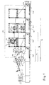
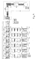
- FIG. 1 shows a simplified, partially schematic and not to the full scale representation of an embodiment of an apparatus according to the invention.
- Four paper webs 1, 2, 3 and 4 are each unrolled in the viewing direction of the feed units (not shown) and deflecting units (in the drawing, a deflection unit for third paper web 12c) is deflected by a right angle in the drawing to the right ,
- the deflection units are designed as so-called turning crosses 59a, 59b, 59c and 59d.
- a turning cross is a deflection unit consisting of at least one cylindrical deflecting roller, wherein the deflecting roller is provided with its own Rotary axis is arranged parallel to the plane defined by the paper surface and at an angle of 45 ° to the direction of running of the incoming paper.
- a first tension adjusting unit 19 By way of example, the first tensioning unit is designated 19d in Figure 1 for the paper web 4 and framed with a dashed line.
- the tension adjusting device 19d consists of a first deflecting roller 81, a variator 82, a nip roll 83, a tension measuring roll 84 and an optional second deflecting roll 85.
- the axes of all rolls are aligned parallel to one another.
- the variator 82 is disposed in the plane of symmetry associated with the first deflecting roller 81 and the tension measuring roller 84.
- the position of the variator 82 may be changed about the variator 82 in the plane of symmetry opposite the first deflecting roller 81 and the tension measuring roller 84 (ie, up and down in the illustration of FIG. 1) at substantially constant wrap angle of the paper web.
- the pressure roller 83 forms with the variator 82 a pair of rollers; it is arranged with pressure closure on the variator 82.
- the paper web is looped around the tension measuring roller 84 so that the web tension can be measured on the tension measuring roller 84 (a force pulling the tension measuring roller 84 upwards in FIG. 1) due to the force effect of the tensioned paper web.
- the bearings (not shown) of the axis of the tension measuring roll 84 are mounted in a force transducer (not shown).
- the second deflecting roller 85 deflects the paper web at the outlet of the tension adjusting device 19d in a desired direction of withdrawal. This function of the second deflecting roller 85 is not essential to the functioning of the arrangement shown as a tension adjusting unit.
- the web-specific processing lines 10a to 10d initially include those already described above essentially identical, first stress adjusting units 19a to 19d. This is followed by different web-specific finishing lines 13a to 13d, a second stress point unit 20a to 20d and means for congruent regulation of the longitudinal registers 14a to 14d. Subsequently, the paper webs 1 to 4 are brought together in the combination guide unit 21 and fed to a common processing line 22.
- the paper web 1 no longer passes through a web-specific refining process.
- the paper web 2 is folded in a folding plow 77 along its longitudinal direction.
- the paper web 3 passes through a gluing unit 72.
- Paper web 4 first passes through a punching device 73 with a punching waste remover 74, to which a collecting container for punching waste 75 is attached, and then a dispensing unit 76 for applying objects, such as reply cards, sample packages or the like, by means of the glue nozzle 78 are attached.
- the common processing line 22 consists in Figure 1 of a Falzpflug 79, which folds the four merged paper webs together in the longitudinal direction, the web scanner 24 and the traction unit 25, which is formed as a pair of two equal, pressed together and against each other rotatably driven draw rollers.
- the common processing section 22 is still attached to a collecting direction 26 for the finished and merged paper webs.
- a format cutter 27 is shown in FIG. In the plan view of Figure 4 can be seen in an exemplary embodiment possible further downstream elements of a collecting device 26, in particular a first rotary format cutter 28, a 90 ° deflection station 29, a second rotary format cutter 30 and a compensating stacking device 31 for the finished products cut to size.
- the second tensioning unit 20a to 20d consists essentially of a pair of unequal, cylindrical press-pressed rollers, namely the thicker, fixed second roller 92 and the thinner, against the stationary second roller 92 Pressed press roller 93.
- the forward speed of the paper web and thus a defined braking action relative to the tractor unit can be achieved via the rotational speed of the press roller 93 and thus on the intermediate section of the paper web, and so that in the common Verbeitungsumble 22 set a defined, the same web tension for all paper webs. Accordingly, compared to the first tensioning unit 19, in particular the pressure roller pair formed by the pressure roller 83 and the variator 82, a pulling action and thus likewise a defined web tension can be established.
- the means for congruent control of the longitudinal registers 14 shown in the example of Figure 1 comprise the longitudinal register setting unit 15, the longitudinal register key 16 and the longitudinal register control means (not shown).
- the longitudinal register adjusting unit 15 is advantageously between the end of the web-specific refining section 13 and arranged directly in front of the merger unit 21 and allows a direct adjustment of the path of the paper web on the web-specific refining section 13.
- a direct adjustment of the path of the paper web takes place in that a guide roller, which is arranged with its axis perpendicular to the direction of the paper web, is pressed against the paper web substantially perpendicular to the surface of the paper web, so that thereby the wrap angle the paper web changes around the guide roller. If the wrap angle becomes greater, the path of travel of the paper web also increases and its register is set back in the direction of travel relative to the register of other paper webs.
- To the longitudinal register adjusting unit 15 shown in Fig. 1 belongs the movable first roller 91 and the stationary second roller 92.
- the position of the first roller 91 substantially in the azimuthal direction around the second roller 92 the wrap angle of the paper web on the second roller 92 and thus the path of the paper web changed.
- a longitudinal position adjusting unit can be combined with a tension adjusting unit to form an arrangement consisting of only three rollers.
- 1 shows the combination of the L Lucasgsregisterstelltechnik 15 with the second tensioning unit 20 to one of only three rollers, namely the movable first roller 91, the fixed second roller 92 and the pressure roller 93, existing arrangement.
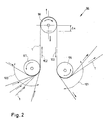
- the longitudinal register may for example also be set directly, with a second embodiment consisting of three rollers shown in FIG.
- a fixed input roller 97 deflects the direction of the incoming paper into the web 1 in a certain, designated with the direction of adjustment 102, the first direction of rotation.
- a reversing roller 98 which is displaceably arranged in the setting direction 102, deflects the direction of travel of the paper web from the setting direction 102 into the exactly opposite direction of reversal 103.
- the likewise fixed output roller 99 deflects the paper web 1 into a freely selectable, wide region 101 of outlet angles.
- the entry angle of the paper web 1 is freely selectable in a wide range 100. It is important that the wrap angle of the paper web around the guide roller 98 is exactly 180 °. This condition is easily met by a suitable choice of the relative arrangement of the input roller 97 and the output roller 99 with respect to the reverse roller 98.
- the position of the deflecting roller 98 can be displaced along the direction of adjustment 102. If the deflecting roller 98 is displaced to (or away from) the input roller 97 or exit roller 99 by a specific distance ⁇ x, the path of travel of the paper web is shortened (extended) by exactly twice the distance 2 ⁇ x. This makes it particularly easy to calibrate the setting of the longitudinal register exactly to the exact distance.
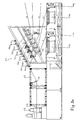
- FIG. 3 shows a scale-true, and in particular in the area of deflection units 59a to 59f realized deflection units and in the area of the merging unit 21 technically more detailed side view of a complete device according to the invention for refining and merging six paper webs 1 to 6.
- Die Paper webs are, as in Figure 1, dispensed in the viewing direction of the viewer from (not shown) feed units, printed in (not shown) digital printing systems and introduced deflected in the apparatus shown on the turnstiles 59a to 59f to the right. After passing through the turning crosses, the paper webs are already spatially over or under one another, but are not yet brought together in the sense of the invention.
- the paper web 6 passes through a dispensing unit 76, is then coated with glue from the glue nozzle 78 and glued together with the paper web 5 to the paper web 5 ' , Then, the paper webs 3, 4 and 5 'each still run separately into a combination of longitudinal register setting unit 15c to 15e and second tension adjusting unit 20c to 20e. The paper webs 3 and 4 then still pass the longitudinal register keys 16c and 16d, before they too, together with the paper web 5, reach the merging unit 21 and are brought together.
- the longitudinal register keys 16a to 16d detect the paper webs 1 to 4 passing in each case past the respective paper webs At regular intervals applied markers and each give a signal to the (not shown) control unit of the device. About the time sequence of the arrival of the signals, the control unit checks whether the longitudinal register of the individual paper webs 1 to 4 are congruent with each other in coverage and detects for each paper web 1 to 4 a possible deviation. If a deviation is detected for one of the paper webs 1 to 4, a control signal is sent to the corresponding longitudinal register adjusting unit 15a to 15d for each paper web deviating in register via an associated longitudinal register control device (not shown) to correct the deviation.
- the web scanner 24 mounted immediately in front of the tractor unit 25 detects the markings applied to the paper web 5 'resting on top of the other paper webs in the area of the merging unit 21 and the subsequent common processing line and outputs corresponding signals to the control unit.
- the control unit detects the common running speed of the merged paper web and can adjust the absolute running speed via a control unit that controls the train unit.
- a possible deviation of the longitudinal register of the paper web 5 'from the longitudinal registers of the paper webs 1 to 4 can be determined from a comparison of the time sequence of the arrival of the signals from the web scanner 24 with the sequence of signals generated by the longitudinal register keys 16a to 16d Paper web 5 'associated longitudinal register adjusting unit 15 e be corrected.
- the merging unit 21 has, as shown in Figure 3, advantageous for at least each of the incoming paper webs 1 to 5 ', a guide roller 94a to 94e and a guide roller 95a to 95e.
- the axes of rotation of all deflecting rollers 94a to 94e are arranged in a plane, whereby the paper webs 1 to 5 'abut each other after passing around the deflecting rollers 94a to 94e.
- Each of the guide rollers is mounted with a force transducer, with which the web tension of the respective paper web is measured.
- the merged paper webs on the common processing line pass through a final folding plow 79, the drawing unit 25, a format cutter and further units (not shown in FIG. 3, but in FIG. 4 in plan view), in particular a first rotary cutter 28, a 90 ° -Umlenkstation 29 and a second size cutter 30.
- the cut from the merged, endless paper web to size, individual finished products of the finishing process are finally stacked in a compensating stacking device 31 on top of each other.
- An overall view of the arrangement and mounting of the functional elements of the device shows a modular construction of the device.
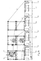
- FIG. 4 shows a top view of the same device, which is shown in side view in FIG. This view again illustrates the modular design of the entire device.
- each of the feeding units 10a to 10f comprises a unwinding unit 40a to 40f, which includes, in particular, the unwinder 41a to 41f shown in Fig. 4 with stock drums 42a to 42f, and the web guiding apparatus 49a to 49f.
- each paper web 1 through 6 passes through a digital printing system 71a through 71f. Then pass through the paper webs 1 to 6 clearly recognizable from above turning crosses 59a to 59f, and run on the following routes already spatially over or under each other, so that in this illustration the elements of the web-specific finishing lines shown in Figure 3 are not recognizable.
- Figure 5 shows a detailed side view of a single feed unit as provided in the apparatus shown in Figures 3 and 4 for each paper web.
- the unwinding device 41 can be clearly seen in the unwinding unit 40 with, inter alia, the supply drum 42 and the web guiding device 49, as well as the digital printing system 71 in the further course of the paper web.
- a supply of a paper web to be finished is rolled up into a roll.
- a paper web is folded in longitudinal sections.
- the folds are advantageously mounted on the paper web synchronously with a possible page register and arranged so that they affect the appearance of the paper web as little as possible disturbing.
Landscapes
- Controlling Rewinding, Feeding, Winding, Or Abnormalities Of Webs (AREA)
- Replacement Of Web Rolls (AREA)
- Laminated Bodies (AREA)
- Registering, Tensioning, Guiding Webs, And Rollers Therefor (AREA)
Claims (47)
- Procédé pour réunir, de façon commandée quant au repérage longitudinal, et améliorer au moins deux bandes de papier, dans lequel chaque bande de papier est munie de marquages appliqués selon des espacements périodiques, procédé pour lequel les différentes bandes de papier parcourent des circuits de transformation spécifiques à la bande, comprenant une unité d'amenée, une unité de déviation optionnelle et une unité d'amélioration spécifique à la bande ; ensuite, elles sont réunies dans une unité d'assemblage, puis passent encore par un circuit de transformation commun à commande du repérage longitudinal, sur lequel des bandes de papier, en option, sont travaillées sur un circuit d'amélioration commun à commande du repérage longitudinal, sur lequel un palpeur de bande optionnel mesure la vitesse de la bande et sur lequel les bandes de papier sont tirées par une unité de traction et reçues dans un dispositif de réception, sachant que, à l'aide de moyens de régulation de la tension mécanique dans la bande, auquel appartiennent une première unité de réglage de la tension mécanique, disposée en amont du circuit d'amélioration spécifique à la bande, et l'unité de traction, la tension mécanique dans la bande des bandes de papier est réglée, et le repérage longitudinal est réglé par des moyens de régulation congruente du repérage longitudinal, auquel appartient un palpeur de repérage longitudinal ;
caractérisé en ce que, pour au moins une bande de papier, les moyens de régulation de la tension mécanique dans la bande contiennent en plus au moins une deuxième unité de réglage de la tension mécanique, qui est disposée en aval du circuit d'amélioration spécifique à la bande et en amont de l'unité d'assemblage, unité au moyen de laquelle la tension mécanique dans la bande, régnant entre la première et la deuxième unité de réglage de tension, et la tension mécanique dans la bande, régnant entre la deuxième unité de réglage de tension et l'unité de traction, sont réglées de façon sensiblement indépendante l'une de l'autre. - Procédé selon la revendication 1, caractérisé en ce que, sur chaque circuit partiel formé par une paire d'unités de réglage de tension, et sur le circuit partiel, formé entre la dernière unité de réglage de tension, en observant dans le sens de défilement, et l'unité de traction, la tension mécanique dans la bande de papier est réglée à une valeur sensiblement constante.
- Procédé selon la revendication 1 ou 2, caractérisé en ce que, en observant dans le sens de défilement de la bande de papier, la tension mécanique dans la bande diminue à la façon d'une cascade, d'un circuit partiel à un autre circuit partiel.
- Procédé selon l'une des revendications 1 à 3, caractérisé en ce que, pour chaque bande de papier, la tension mécanique dans la bande, régnant entre la dernière unité de réglage de tension, en observant dans le sens de défilement de la bande de papier, et l'unité de traction, est réglée à une valeur sensiblement identique, commune pour toutes les bandes de papier.
- Procédé selon l'une des revendications 1 à 4, caractérisé en ce que les moyens de réglage de la tension mécanique dans la bande et l'unité de traction sont réalisés de manière que la tension mécanique dans la bande soit réglée sensiblement à une valeur constante sur la largeur de la bande de papier.
- Procédé selon l'une des revendications 1 à 5, caractérisé en ce que pour au moins une bande de papier, le repérage longitudinal est réglé de façon sensiblement indépendante de la tension mécanique dans la bande.
- Procédé selon l'une des revendications 1 à 6, caractérisé en ce qu'au moins une bande de papier est maintenue sous tension mécanique, jusqu'à la dernière unité de réglage de la bande, en observant dans le sens de défilement.
- Procédé selon l'une des revendications 1 à 7, caractérisé en ce que, pour au moins une bande de papier, les moyens pour régler le repérage longitudinal comprennent une unité de réglage du repérage longitudinal optionnelle et un dispositif de réglage du repérage longitudinal.
- Procédé selon l'une des revendications 1 à 8, caractérisé en ce que, dans au moins un circuit de transformation spécifique à la bande, le repérage longitudinal est réglé par le biais du réglage de la tension mécanique dans la bande, au moyen de la première unité de réglage de tension, en exploitant l'étirement de la bande, lié à l'élasticité de la bande.
- Procédé selon l'une des revendications 1 à 9, caractérisé en ce que, en au moins un circuit de transformation spécifique à la bande, le repérage longitudinal est réglé au moyen de l'unité de réglage de repérage longitudinal, par une modification de la distance de défilement de la bande de papier à l'intérieur du circuit de transformation spécifique à la bande.
- Dispositif pour réunir, avec un contrôle du repérage longitudinal, et pour améliorer au moins deux bandes de papier, composé d'au moins deux circuits de transformation spécifiques à la bande, qui de leur côté contiennent une unité d'amenée, une unité de déviation optionnelle et une unité d'amélioration spécifique à la bande, une unité d'assemblage ; un circuit de transformation commun, à contrôle du repérage en longueur, qui contient de son côté un circuit d'amélioration commun à contrôle du repérage en longueur, optionnel, un palpeur de bande optionnel et une unité de traction ; un dispositif de réception et un dispositif de commande ; chaque bande de papier est munie de marquages, appliqués selon des espacements périodiques ; ledit dispositif comprenant en outre des moyens pour la régulation de la tension mécanique dans la bande, auxquels appartiennent une première unité de réglage de tension, disposée en amont du circuit d'amélioration spécifique à bande, et une unité de traction ; et des moyens de régulation du repérage longitudinal auxquels appartient un palpeur de repérage longitudinal, caractérisé en ce que, pour au moins une bande de papier, les moyens de régulation de la tension mécanique dans la bande comprennent en plus une deuxième unité de réglage de tension, qui est disposée en aval du circuit d'amélioration spécifique à la bande et en amont de l'unité d'assemblage.
- Dispositif selon la revendication 11, caractérisé en ce que, pour chaque bande de papier, les moyens de régulation de tension mécanique dans la bande comprennent en plus au moins une deuxième unité de réglage de la tension, disposée en aval du circuit d'amélioration spécifique à la bande et en amont de l'unité d'assemblage.
- Dispositif selon la revendication 11 ou 12, caractérisé en ce que, pour chaque bande de papier, la première unité de réglage de tension est disposée directement en amont de l'unité d'amélioration spécifique à la bande.
- Dispositif selon l'une des revendications 11 à 13, caractérisé en ce que, pour au moins un circuit de traitement spécifique à la bande, les moyens de régulation du repérage longitudinal contiennent en plus une autre unité de régulation du repérage longitudinal et un dispositif de régulation du repérage longitudinal.
- Dispositif selon la revendication 14, caractérisé en ce que, pour au moins un circuit de transformation spécifique à la bande, les moyens de régulation du repérage longitudinal permettent de régler le repérage longitudinal de la bande de papier, indépendamment de la tension mécanique dans la bande.
- Dispositif selon l'une des revendications 11 à 15, caractérisé en ce qu'au moins deux postes de transformation différents appartiennent à au moins un circuit d'amélioration spécifique à la bande.
- Dispositif selon la revendication 16, caractérisé en ce qu'une unité de réglage de tension supplémentaire est disposée entre au moins deux postes de transformation.
- Dispositif selon l'une des revendications 11 à 17, caractérisé en ce que, à l'intérieur d'au moins un circuit de transformation spécifique à la bande, au moins un poste de transformation sert à réunir une bande de papier à une autre bande de papier.
- Dispositif selon l'une des revendications 11 à 18, caractérisé en ce que les éléments du dispositif sont chacun de réalisation modulaire, de manière que l'ensemble du dispositif puisse être reconfiguré ou étendu, pour un faible coût, par enlèvement ou addition d'éléments individuels.
- Dispositif selon l'une des revendications 11 à 19, caractérisé en ce que l'unité de traction est disposée directement en aval du circuit d'amélioration à contrôle du repérage longitudinal, et en amont du dispositif de réception.
- Dispositif selon l'une des revendications 11 à 20, caractérisé en ce que les moyens de régulation de la tension mécanique dans la bande sont réalisés de manière que la tension mécanique dans la bande soit pratiquement constante sur la largeur de la bande.
- Dispositif selon la revendication 21, caractérisé en ce qu'au moins une unité de réglage de la tension et/ou l'unité de traction est formée d'une paire de rouleaux de traction.
- Dispositif selon la revendication 22, caractérisé en ce qu'au moins une paire de rouleaux de traction est une paire de rouleaux en caoutchouc.
- Dispositif selon l'une des revendications 22 à 23, caractérisé en ce que les paires de rouleaux de traction sont munies, sur leur périphérie, d'un profil pour recevoir les produits d'amélioration correspondants.
- Dispositif selon l'une des revendications 22 à 24, caractérisé en ce que les axes des paires de rouleaux de traction sont alignés les uns par rapport aux autres et disposés dans un plan perpendiculaire à la direction de défilement de la bande de papier.
- Dispositif selon l'une des revendications 11 à 25, caractérisé en ce que les unités de réglage de la tension sont commandées indépendamment les unes des autres par l'unité de commande.
- Dispositif selon l'une des revendications 11 à 26, caractérisé en ce que l'unité d'amenée (10) est une unité de déroulement (40), composée au moins d'un tambour de réserve (42) et d'une paire de rouleaux de traction et dans laquelle la bande de papier se présente enroulée sur un tambour de réserve (42).
- Dispositif selon la revendication 27, caractérisé en ce que la paire de rouleaux de traction est composée du rouleau de réserve (42) lui-même et d'un rouleau d'extraction, disposé pressé contre la couche la plus haute, enroulée sur le tambour de réserve (42), de la bande de papier.
- Dispositif selon la revendication 27, caractérisé en ce que l'unité de déroulement (40) est formée au moins d'un tambour de réserve (42), d'un rouleau d'extraction, pressé contre celui-ci, et d'une paire de rouleaux de traction.
- Dispositif selon l'une des revendications 11 à 26, caractérisé en ce que l'unité d'amenée est une unité de dépliage, composée au moins d'un récipient de réserve et d'une paire, soumise à un contrôle de la vitesse, de rouleaux d'entraînement, et dans laquelle la bande de papier se présente à l'état plié dans le récipient de réserve.
- Dispositif selon l'une des revendications 11 à 30, caractérisé en ce que le dispositif de réception est formé au moins d'un rouleau de réception.
- Dispositif selon l'une des revendications 11 à 30, caractérisé en ce que le dispositif de réception est formé d'un découpeur au format, d'un dispositif d'empilage, d'un dispositif de comptage optionnel et d'un dispositif d'emballage ou de banderolage, optionnel.
- Dispositif selon l'une des revendications 11 à 32, caractérisé en ce que l'unité de renvoi (12) optionnelle est disposée entre l'unité d'amenée (11) et le début du circuit d'amélioration (13) spécifique à la bande.
- Dispositif selon l'une des revendications 11 à 32, caractérisé en ce que l'unité de renvoi (12) optionnelle est disposée entre la fin du circuit d'amélioration (13) spécifique à la bande et l'unité d'assemblage (21).
- Dispositif selon l'une des revendications 1 à 24, caractérisé en ce que l'unité de renvoi (12) optionnelle est une croix de retournement (59).
- Dispositif selon l'une des revendications 11 à 35, caractérisé en ce que, en au moins un circuit de transformation (13) spécifique à la bande, le repérage longitudinal peut être réglé par le biais du réglage de la tension mécanique dans la bande, au moyen de la première unité de réglage de tension (19), en exploitant l'étirement de la bande, lié à élasticité de la bande.
- Dispositif selon l'une des revendications 11 à 35, caractérisé en ce que, en au moins un circuit de transformation (13) spécifique à la bande, le repérage longitudinal peut être réglé au moyen de l'unité de réglage de repérage longitudinal (15), par modification de la course de défilement de la bande de papier à l'intérieur du circuit de transformation (13) spécifique à la bande.
- Dispositif selon la revendication 37, caractérisé en ce que l'unité de réglage du repérage longitudinal (15) est disposée entre la fin du circuit d'amélioration (13) spécifique à la bande et l'unité d'assemblage (21).
- Dispositif selon la revendication 37 ou 38, caractérisé en ce que, en ce que l'unité de réglage du repérage longitudinal (15) est réalisée sous forme d'une paire de rouleaux, avec un premier rouleau (91) mobile et un deuxième rouleau (92) stationnaire, dans laquelle, par modification de position du premier rouleau (91), sensiblement en direction azimutale autour du deuxième rouleau (92), l'angle d'enlacement de la bande de papier sur le deuxième rouleau (92) peut être réglé.
- Dispositif selon l'une des revendications 11 à 39, caractérisé en ce qu'au moins une unité de réglage de tension (20) comprend un rouleau presseur (93) et un deuxième rouleau (92) faisant office de rouleau conjugué, le rouleau presseur (93) étant entraîné avec une vitesse de rotation réglable et disposé sur le deuxième rouleau (92), avec une liaison obtenue par l'action de la pression.
- Dispositif selon l'une des revendications 11 à 40, caractérisé en ce qu'au moins une unité de réglage de repérage longitudinal (15) est combinée à une unité de réglage de la tension (20), pour former un ensemble.
- Dispositif selon les revendications 40 et 41, caractérisé en ce que le rouleau presseur (93) de l'unité de réglage de tension est disposé avec une liaison par pressage sur l'un des deux rouleaux (91, 92) de l'unité de réglage de repérage longitudinal (15), de préférence sur le deuxième rouleau (92) stationnaire.
- Dispositif selon l'une des revendications 11 à 42, caractérisé en ce que, en au moins un circuit de transformation spécifique à la bande, une première unité de réglage de tension (19) est formée essentiellement d'un premier rouleau de renvoi (81), d'un variateur (82), d'un rouleau de pressage (83), d'un rouleau de mesure de tension mécanique (84) et d'un deuxième renvoi (85) optionnel ; sachant que les axes de tous les rouleaux sont orientés parallèlement les uns aux autres, le variateur (82) étant situé dans le plan de symétrie appartenant au premier rouleau de renvoi (81) et au rouleau de mesure de tension mécanique (84), la position du variateur (82) dans le plan de symétrie, par rapport au premier rouleau de renvoi (81) et au rouleau de mesure de tension mécanique (84), pouvant être modifié, alors que l'angle d'enlacement reste constant ; le rouleau de pressage (83) étant disposé, avec une liaison par pressage, sur le variateur (82), la bande de papier étant enlacée autour du rouleau de mesure de tension mécanique (84), et la tension mécanique dans la bande étant mesurée par l'intermédiaire de l'effet de force de la bande de papier tendue sur le rouleau de mesure de tension mécanique (84) ; et le deuxième rouleau de renvoi optionnel déviant la bande de papier en une direction de sortie souhaitée.
- Dispositif selon l'une des revendications 11 à 43, caractérisé en ce que l'unité d'assemblage (21) contient, de manière correspondante au nombre des bandes de papier à réunir, au moins deux rouleaux de renvoi (94), disposés dans un plan, tel que les axes des rouleaux de renvoi (94) sont parallèles et que la direction de défilement de la bande de papier, après séparation vis-à-vis des rouleaux de renvoi (94), est parallèle au plan cité.
- Dispositif selon l'une des revendications 11 à 44, caractérisé en ce que la tension mécanique dans la bande régnant entre la deuxième unité de réglage de tension et l'unité d'assemblage est mesurée, par l'intermédiaire de la force de traction, agissant sur les rouleaux de renvoi (94) de l'unité d'assemblage (21), dans la bande de papier.
- Dispositif selon l'une des revendications 11 à 45, caractérisé en ce que les palpeurs de repérage longitudinal (16) sont disposés directement en amont de l'unité d'assemblage (21).
- Dispositif selon l'une des revendications 11 à 46, caractérisé en ce que, en au moins un circuit de transformation spécifique à la bande, est utilisé une technique d'impression numérique, en tant que processus d'amélioration.
Applications Claiming Priority (3)
| Application Number | Priority Date | Filing Date | Title |
|---|---|---|---|
| CH101700 | 2000-05-17 | ||
| CH10172000 | 2000-05-19 | ||
| PCT/EP2001/005649 WO2001089971A1 (fr) | 2000-05-19 | 2001-05-17 | Procede et dispositif pour reunir des bandes de papier differentes |
Publications (2)
| Publication Number | Publication Date |
|---|---|
| EP1282575A1 EP1282575A1 (fr) | 2003-02-12 |
| EP1282575B1 true EP1282575B1 (fr) | 2006-08-02 |
Family
ID=4552773
Family Applications (1)
| Application Number | Title | Priority Date | Filing Date |
|---|---|---|---|
| EP01940494A Expired - Lifetime EP1282575B1 (fr) | 2000-05-19 | 2001-05-17 | Procede et dispositif pour reunir des bandes de papier differentes |
Country Status (12)
| Country | Link |
|---|---|
| US (1) | US20040026056A1 (fr) |
| EP (1) | EP1282575B1 (fr) |
| JP (1) | JP2003534174A (fr) |
| AT (1) | ATE334924T1 (fr) |
| AU (1) | AU2001274048A1 (fr) |
| CA (1) | CA2409270A1 (fr) |
| DE (1) | DE50110622D1 (fr) |
| ES (1) | ES2269417T3 (fr) |
| HK (1) | HK1049650A1 (fr) |
| PL (1) | PL357824A1 (fr) |
| RU (1) | RU2265570C2 (fr) |
| WO (1) | WO2001089971A1 (fr) |
Families Citing this family (9)
| Publication number | Priority date | Publication date | Assignee | Title |
|---|---|---|---|---|
| DE10335887B4 (de) * | 2003-08-06 | 2007-11-08 | Man Roland Druckmaschinen Ag | Verfahren und Vorrichtung zum Regeln eines Schnittregisterfehlers und einer Bahnzugkraft einer Rollenrotationsdruckmaschine |
| US20070174045A1 (en) * | 2006-01-25 | 2007-07-26 | International Business Machines Corporation | Automatic acronym expansion using pop-ups |
| RU2435726C2 (ru) * | 2006-03-16 | 2011-12-10 | Алтернапак Холдинг Б.В. | Устройство для выполнения повторяемых операций |
| RU2436722C2 (ru) * | 2006-09-03 | 2011-12-20 | Гиц Аг | Устройство для приводки |
| BRPI0911157A2 (pt) | 2008-04-22 | 2016-09-13 | Sharp Kk | pacote eletrônico, dispositivo de exibição e dispositivo eletrônico |
| JP4782893B2 (ja) * | 2008-04-22 | 2011-09-28 | シャープ株式会社 | 電子パッケージ、表示装置、および電子機器 |
| JP2012046305A (ja) * | 2010-08-26 | 2012-03-08 | Tokyo Kikai Seisakusho Ltd | デジタル印刷による折丁作成システム及びデジタル印刷による折丁作成方法 |
| GB201306974D0 (en) * | 2013-04-17 | 2013-05-29 | Parkburn Prec Handling Systems Ltd | Load Bearing Apparatus and Method |
| CN105565036B (zh) * | 2016-03-22 | 2017-12-22 | 昆山巨闳机械科技有限公司 | 双卷铜箔裁切机 |
Family Cites Families (8)
| Publication number | Priority date | Publication date | Assignee | Title |
|---|---|---|---|---|
| US2114293A (en) * | 1936-11-14 | 1938-04-19 | Carbon Interleaved Forms Corp | Machine for making manifold forms |
| US2453982A (en) * | 1946-01-28 | 1948-11-16 | Hoe & Co R | Printing press compensator |
| US2818003A (en) * | 1953-09-03 | 1957-12-31 | St Regis Paper Co | Apparatus for making a multi-ply valve bag having an extended intermediate valve ply |
| US3556509A (en) * | 1968-08-21 | 1971-01-19 | Harris Intertype Corp | Printed web ribbon registration control system |
| EP0328783B1 (fr) * | 1988-02-19 | 1992-04-08 | Asea Brown Boveri Ag | Méthode de détermination de la position de coupe d'une machine d'imprimerie |
| US5117610A (en) * | 1990-09-21 | 1992-06-02 | Dittler Brothers, Incorporated | Methods and apparatus for printing and collating materials from multiple webs |
| ATE168967T1 (de) * | 1994-04-13 | 1998-08-15 | Branstal Printing Participatio | Vorrichtung und verfahren zum zusammenführen und veredeln mehrerer papierbahnen |
| DE4435429C2 (de) * | 1994-10-04 | 2000-07-06 | Wifag Maschf | Rollenrotationsdruckmaschine |
-
2001
- 2001-05-17 WO PCT/EP2001/005649 patent/WO2001089971A1/fr not_active Ceased
- 2001-05-17 EP EP01940494A patent/EP1282575B1/fr not_active Expired - Lifetime
- 2001-05-17 AU AU2001274048A patent/AU2001274048A1/en not_active Abandoned
- 2001-05-17 HK HK03101502.6A patent/HK1049650A1/zh unknown
- 2001-05-17 PL PL01357824A patent/PL357824A1/xx not_active IP Right Cessation
- 2001-05-17 AT AT01940494T patent/ATE334924T1/de not_active IP Right Cessation
- 2001-05-17 US US10/276,560 patent/US20040026056A1/en not_active Abandoned
- 2001-05-17 ES ES01940494T patent/ES2269417T3/es not_active Expired - Lifetime
- 2001-05-17 JP JP2001586168A patent/JP2003534174A/ja not_active Withdrawn
- 2001-05-17 DE DE50110622T patent/DE50110622D1/de not_active Expired - Lifetime
- 2001-05-17 CA CA002409270A patent/CA2409270A1/fr not_active Abandoned
- 2001-05-17 RU RU2002134182/12A patent/RU2265570C2/ru not_active IP Right Cessation
Also Published As
| Publication number | Publication date |
|---|---|
| JP2003534174A (ja) | 2003-11-18 |
| WO2001089971A1 (fr) | 2001-11-29 |
| HK1049650A1 (zh) | 2003-05-23 |
| CA2409270A1 (fr) | 2002-11-19 |
| DE50110622D1 (de) | 2006-09-14 |
| PL357824A1 (en) | 2004-07-26 |
| ATE334924T1 (de) | 2006-08-15 |
| RU2265570C2 (ru) | 2005-12-10 |
| ES2269417T3 (es) | 2007-04-01 |
| EP1282575A1 (fr) | 2003-02-12 |
| AU2001274048A1 (en) | 2001-12-03 |
| US20040026056A1 (en) | 2004-02-12 |
Similar Documents
| Publication | Publication Date | Title |
|---|---|---|
| EP2305466B1 (fr) | Presse rotative à format variable | |
| DE10033467A1 (de) | Falzapparatanordnung in einer Rollenrotations-Zeitungsdruckmaschine | |
| EP1299242B1 (fr) | Installation de production continue d'une bande de textile imprime, notamment d'une bande d'etiquettes | |
| EP3459724B1 (fr) | Installation de carton ondulé | |
| DE602004012202T2 (de) | Verfahren und Vorrichtung für das Überlappung von Bogen | |
| DE102010049057A1 (de) | Bogenfalzmaschine und Verfahren zum Betreiben einer Falzmaschine | |
| EP1282575A1 (fr) | Procede et dispositif pour reunir des bandes de papier differentes | |
| EP0755356A1 (fr) | Procede et dispositif permettant de reunir et de traiter des bandes de papier | |
| EP0518053A1 (fr) | Procédé et appareil pour la fabrication de carton ondulé imprimé de grande largeur | |
| EP3059195B1 (fr) | Dispositif de pliage et procédé | |
| DE19819890C2 (de) | Anordnung zum Zusammenführen von Bedruckstoffbahnen vor einem Längsfalztrichter | |
| EP3118147B1 (fr) | Plieuse a poches et plieuse comprenant une telle plieuse a poches | |
| EP0908310A2 (fr) | Entraínement de bandes au-dessus d'un groupe de pliage | |
| EP2275373A1 (fr) | Procédé et dispositif d'assemblage continu d'au moins deux flux de tuiles de produits d'impression plats | |
| EP2319788B1 (fr) | Plieuse dotée d'un dispositif d'extraction | |
| EP0384147A1 (fr) | Procédé et appareil pour l'emmagasinage intermédiaire de produits d'imprimerie pliés, à plusieurs feuilles, comme journaux, magazines et parties de ceux-ci | |
| DE60206238T2 (de) | Vorrichtung und Verfahren zum Verpacken von Gegenständen | |
| DE19954301A1 (de) | Verfahren und Anlage zur Herstellung von mindestens 4-lagiger Wellpappe | |
| DE102022117744A1 (de) | Verfahren zum Fördern eines Fadenstrangs, Verfahren zum Synchronisieren eines Fadenstrangs mit einer Papierbahn, Verfahren zum Synchronisieren eines Fadens mit einer Papierbahn, Vorrichtung zum Durchführen der Verfahren | |
| DE60201410T2 (de) | Verfahren zur Herstellung von vierschichtigem Toilettenpapier und Vorrichtung dafür | |
| EP3467200B1 (fr) | Dispositif de fabrication et procédé de fabrication pour papier de sécurité | |
| CH719395A1 (de) | Flachprägedruckmaschine mit einer Folienbahnführungs- und Transporteinrichtung. | |
| EP0778129A1 (fr) | Machine d'impression digital et procédé pour son transport de feuilles | |
| DE19828124A1 (de) | Anlage zur Herstellung von 5-lagiger Wellpappe | |
| DE10020153A1 (de) | Vorrichtung und Verfahren zum Umlenken von Bedruckstoffbogen |
Legal Events
| Date | Code | Title | Description |
|---|---|---|---|
| PUAI | Public reference made under article 153(3) epc to a published international application that has entered the european phase |
Free format text: ORIGINAL CODE: 0009012 |
|
| 17P | Request for examination filed |
Effective date: 20021028 |
|
| AK | Designated contracting states |
Designated state(s): AT BE CH CY DE DK ES FI FR GB GR IE IT LI LU MC NL PT SE TR |
|
| AX | Request for extension of the european patent |
Extension state: AL LT LV MK RO SI |
|
| GRAP | Despatch of communication of intention to grant a patent |
Free format text: ORIGINAL CODE: EPIDOSNIGR1 |
|
| GRAS | Grant fee paid |
Free format text: ORIGINAL CODE: EPIDOSNIGR3 |
|
| GRAA | (expected) grant |
Free format text: ORIGINAL CODE: 0009210 |
|
| AK | Designated contracting states |
Kind code of ref document: B1 Designated state(s): AT BE CH CY DE DK ES FI FR GB GR IE IT LI LU MC NL PT SE TR |
|
| AX | Request for extension of the european patent |
Extension state: SI |
|
| PG25 | Lapsed in a contracting state [announced via postgrant information from national office to epo] |
Ref country code: IT Free format text: LAPSE BECAUSE OF FAILURE TO SUBMIT A TRANSLATION OF THE DESCRIPTION OR TO PAY THE FEE WITHIN THE PRESCRIBED TIME-LIMIT;WARNING: LAPSES OF ITALIAN PATENTS WITH EFFECTIVE DATE BEFORE 2007 MAY HAVE OCCURRED AT ANY TIME BEFORE 2007. THE CORRECT EFFECTIVE DATE MAY BE DIFFERENT FROM THE ONE RECORDED. Effective date: 20060802 Ref country code: FI Free format text: LAPSE BECAUSE OF FAILURE TO SUBMIT A TRANSLATION OF THE DESCRIPTION OR TO PAY THE FEE WITHIN THE PRESCRIBED TIME-LIMIT Effective date: 20060802 Ref country code: NL Free format text: LAPSE BECAUSE OF FAILURE TO SUBMIT A TRANSLATION OF THE DESCRIPTION OR TO PAY THE FEE WITHIN THE PRESCRIBED TIME-LIMIT Effective date: 20060802 Ref country code: IE Free format text: LAPSE BECAUSE OF FAILURE TO SUBMIT A TRANSLATION OF THE DESCRIPTION OR TO PAY THE FEE WITHIN THE PRESCRIBED TIME-LIMIT Effective date: 20060802 |
|
| REG | Reference to a national code |
Ref country code: GB Ref legal event code: FG4D Free format text: NOT ENGLISH |
|
| REG | Reference to a national code |
Ref country code: CH Ref legal event code: EP |
|
| REG | Reference to a national code |
Ref country code: IE Ref legal event code: FG4D Free format text: LANGUAGE OF EP DOCUMENT: GERMAN |
|
| REF | Corresponds to: |
Ref document number: 50110622 Country of ref document: DE Date of ref document: 20060914 Kind code of ref document: P |
|
| PG25 | Lapsed in a contracting state [announced via postgrant information from national office to epo] |
Ref country code: SE Free format text: LAPSE BECAUSE OF FAILURE TO SUBMIT A TRANSLATION OF THE DESCRIPTION OR TO PAY THE FEE WITHIN THE PRESCRIBED TIME-LIMIT Effective date: 20061102 Ref country code: DK Free format text: LAPSE BECAUSE OF FAILURE TO SUBMIT A TRANSLATION OF THE DESCRIPTION OR TO PAY THE FEE WITHIN THE PRESCRIBED TIME-LIMIT Effective date: 20061102 |
|
| GBT | Gb: translation of ep patent filed (gb section 77(6)(a)/1977) |
Effective date: 20061025 |
|
| REG | Reference to a national code |
Ref country code: CH Ref legal event code: NV Representative=s name: BUECHEL, KAMINSKI & PARTNER PATENTANWAELTE ESTABLI |
|
| NLV1 | Nl: lapsed or annulled due to failure to fulfill the requirements of art. 29p and 29m of the patents act | ||
| PG25 | Lapsed in a contracting state [announced via postgrant information from national office to epo] |
Ref country code: PT Free format text: LAPSE BECAUSE OF FAILURE TO SUBMIT A TRANSLATION OF THE DESCRIPTION OR TO PAY THE FEE WITHIN THE PRESCRIBED TIME-LIMIT Effective date: 20070102 |
|
| REG | Reference to a national code |
Ref country code: IE Ref legal event code: FD4D |
|
| REG | Reference to a national code |
Ref country code: ES Ref legal event code: FG2A Ref document number: 2269417 Country of ref document: ES Kind code of ref document: T3 |
|
| EN | Fr: translation not filed | ||
| PLBE | No opposition filed within time limit |
Free format text: ORIGINAL CODE: 0009261 |
|
| STAA | Information on the status of an ep patent application or granted ep patent |
Free format text: STATUS: NO OPPOSITION FILED WITHIN TIME LIMIT |
|
| 26N | No opposition filed |
Effective date: 20070503 |
|
| BERE | Be: lapsed |
Owner name: BRANSTAL PRINTING PARTICIPATION ESTABLISHMENT Effective date: 20070531 |
|
| PG25 | Lapsed in a contracting state [announced via postgrant information from national office to epo] |
Ref country code: MC Free format text: LAPSE BECAUSE OF NON-PAYMENT OF DUE FEES Effective date: 20070531 |
|
| PG25 | Lapsed in a contracting state [announced via postgrant information from national office to epo] |
Ref country code: BE Free format text: LAPSE BECAUSE OF NON-PAYMENT OF DUE FEES Effective date: 20070531 |
|
| PG25 | Lapsed in a contracting state [announced via postgrant information from national office to epo] |
Ref country code: FR Free format text: LAPSE BECAUSE OF FAILURE TO SUBMIT A TRANSLATION OF THE DESCRIPTION OR TO PAY THE FEE WITHIN THE PRESCRIBED TIME-LIMIT Effective date: 20070511 Ref country code: GR Free format text: LAPSE BECAUSE OF FAILURE TO SUBMIT A TRANSLATION OF THE DESCRIPTION OR TO PAY THE FEE WITHIN THE PRESCRIBED TIME-LIMIT Effective date: 20061103 |
|
| PG25 | Lapsed in a contracting state [announced via postgrant information from national office to epo] |
Ref country code: AT Free format text: LAPSE BECAUSE OF NON-PAYMENT OF DUE FEES Effective date: 20070517 |
|
| PG25 | Lapsed in a contracting state [announced via postgrant information from national office to epo] |
Ref country code: FR Free format text: LAPSE BECAUSE OF FAILURE TO SUBMIT A TRANSLATION OF THE DESCRIPTION OR TO PAY THE FEE WITHIN THE PRESCRIBED TIME-LIMIT Effective date: 20060802 |
|
| PG25 | Lapsed in a contracting state [announced via postgrant information from national office to epo] |
Ref country code: LU Free format text: LAPSE BECAUSE OF NON-PAYMENT OF DUE FEES Effective date: 20070517 Ref country code: CY Free format text: LAPSE BECAUSE OF FAILURE TO SUBMIT A TRANSLATION OF THE DESCRIPTION OR TO PAY THE FEE WITHIN THE PRESCRIBED TIME-LIMIT Effective date: 20060802 |
|
| PG25 | Lapsed in a contracting state [announced via postgrant information from national office to epo] |
Ref country code: TR Free format text: LAPSE BECAUSE OF FAILURE TO SUBMIT A TRANSLATION OF THE DESCRIPTION OR TO PAY THE FEE WITHIN THE PRESCRIBED TIME-LIMIT Effective date: 20060802 |
|
| REG | Reference to a national code |
Ref country code: CH Ref legal event code: PFA Owner name: BRANSTAL PRINTING PARTICIPATION ESTABLISHMENT Free format text: BRANSTAL PRINTING PARTICIPATION ESTABLISHMENT#INDUSTRIESTRASSE 308#FL-9491 RUGGELL (LI) -TRANSFER TO- BRANSTAL PRINTING PARTICIPATION ESTABLISHMENT#INDUSTRIESTRASSE 308#FL-9491 RUGGELL (LI) |
|
| REG | Reference to a national code |
Ref country code: HK Ref legal event code: WD Ref document number: 1049650 Country of ref document: HK |
|
| PGFP | Annual fee paid to national office [announced via postgrant information from national office to epo] |
Ref country code: ES Payment date: 20120523 Year of fee payment: 12 |
|
| PGFP | Annual fee paid to national office [announced via postgrant information from national office to epo] |
Ref country code: GB Payment date: 20130521 Year of fee payment: 13 |
|
| PGFP | Annual fee paid to national office [announced via postgrant information from national office to epo] |
Ref country code: DE Payment date: 20140603 Year of fee payment: 14 Ref country code: CH Payment date: 20140526 Year of fee payment: 14 |
|
| GBPC | Gb: european patent ceased through non-payment of renewal fee |
Effective date: 20140517 |
|
| PG25 | Lapsed in a contracting state [announced via postgrant information from national office to epo] |
Ref country code: GB Free format text: LAPSE BECAUSE OF NON-PAYMENT OF DUE FEES Effective date: 20140517 |
|
| REG | Reference to a national code |
Ref country code: ES Ref legal event code: FD2A Effective date: 20150629 |
|
| PG25 | Lapsed in a contracting state [announced via postgrant information from national office to epo] |
Ref country code: ES Free format text: LAPSE BECAUSE OF NON-PAYMENT OF DUE FEES Effective date: 20140518 |
|
| REG | Reference to a national code |
Ref country code: DE Ref legal event code: R119 Ref document number: 50110622 Country of ref document: DE |
|
| REG | Reference to a national code |
Ref country code: CH Ref legal event code: PL |
|
| PG25 | Lapsed in a contracting state [announced via postgrant information from national office to epo] |
Ref country code: CH Free format text: LAPSE BECAUSE OF NON-PAYMENT OF DUE FEES Effective date: 20150531 Ref country code: LI Free format text: LAPSE BECAUSE OF NON-PAYMENT OF DUE FEES Effective date: 20150531 |
|
| PG25 | Lapsed in a contracting state [announced via postgrant information from national office to epo] |
Ref country code: DE Free format text: LAPSE BECAUSE OF NON-PAYMENT OF DUE FEES Effective date: 20151201 |