EP1283094A2 - Vorrichtung zum Trimmen mit einem Rotationswerkzeug - Google Patents
Vorrichtung zum Trimmen mit einem Rotationswerkzeug Download PDFInfo
- Publication number
- EP1283094A2 EP1283094A2 EP02016918A EP02016918A EP1283094A2 EP 1283094 A2 EP1283094 A2 EP 1283094A2 EP 02016918 A EP02016918 A EP 02016918A EP 02016918 A EP02016918 A EP 02016918A EP 1283094 A2 EP1283094 A2 EP 1283094A2
- Authority
- EP
- European Patent Office
- Prior art keywords
- knife
- anvil
- shaft
- spindle
- cutting
- Prior art date
- Legal status (The legal status is an assumption and is not a legal conclusion. Google has not performed a legal analysis and makes no representation as to the accuracy of the status listed.)
- Withdrawn
Links
Images


Classifications
-
- B—PERFORMING OPERATIONS; TRANSPORTING
- B26—HAND CUTTING TOOLS; CUTTING; SEVERING
- B26D—CUTTING; DETAILS COMMON TO MACHINES FOR PERFORATING, PUNCHING, CUTTING-OUT, STAMPING-OUT OR SEVERING
- B26D7/00—Details of apparatus for cutting, cutting-out, stamping-out, punching, perforating, or severing by means other than cutting
- B26D7/26—Means for mounting or adjusting the cutting member; Means for adjusting the stroke of the cutting member
- B26D7/2628—Means for adjusting the position of the cutting member
- B26D7/2635—Means for adjusting the position of the cutting member for circular cutters
-
- Y—GENERAL TAGGING OF NEW TECHNOLOGICAL DEVELOPMENTS; GENERAL TAGGING OF CROSS-SECTIONAL TECHNOLOGIES SPANNING OVER SEVERAL SECTIONS OF THE IPC; TECHNICAL SUBJECTS COVERED BY FORMER USPC CROSS-REFERENCE ART COLLECTIONS [XRACs] AND DIGESTS
- Y10—TECHNICAL SUBJECTS COVERED BY FORMER USPC
- Y10S—TECHNICAL SUBJECTS COVERED BY FORMER USPC CROSS-REFERENCE ART COLLECTIONS [XRACs] AND DIGESTS
- Y10S83/00—Cutting
- Y10S83/929—Particular nature of work or product
- Y10S83/934—Book, being made, e.g. trimming a signature
-
- Y—GENERAL TAGGING OF NEW TECHNOLOGICAL DEVELOPMENTS; GENERAL TAGGING OF CROSS-SECTIONAL TECHNOLOGIES SPANNING OVER SEVERAL SECTIONS OF THE IPC; TECHNICAL SUBJECTS COVERED BY FORMER USPC CROSS-REFERENCE ART COLLECTIONS [XRACs] AND DIGESTS
- Y10—TECHNICAL SUBJECTS COVERED BY FORMER USPC
- Y10T—TECHNICAL SUBJECTS COVERED BY FORMER US CLASSIFICATION
- Y10T83/00—Cutting
- Y10T83/283—With means to control or modify temperature of apparatus or work
- Y10T83/293—Of tool
-
- Y—GENERAL TAGGING OF NEW TECHNOLOGICAL DEVELOPMENTS; GENERAL TAGGING OF CROSS-SECTIONAL TECHNOLOGIES SPANNING OVER SEVERAL SECTIONS OF THE IPC; TECHNICAL SUBJECTS COVERED BY FORMER USPC CROSS-REFERENCE ART COLLECTIONS [XRACs] AND DIGESTS
- Y10—TECHNICAL SUBJECTS COVERED BY FORMER USPC
- Y10T—TECHNICAL SUBJECTS COVERED BY FORMER US CLASSIFICATION
- Y10T83/00—Cutting
- Y10T83/929—Tool or tool with support
- Y10T83/9372—Rotatable type
- Y10T83/9403—Disc type
-
- Y—GENERAL TAGGING OF NEW TECHNOLOGICAL DEVELOPMENTS; GENERAL TAGGING OF CROSS-SECTIONAL TECHNOLOGIES SPANNING OVER SEVERAL SECTIONS OF THE IPC; TECHNICAL SUBJECTS COVERED BY FORMER USPC CROSS-REFERENCE ART COLLECTIONS [XRACs] AND DIGESTS
- Y10—TECHNICAL SUBJECTS COVERED BY FORMER USPC
- Y10T—TECHNICAL SUBJECTS COVERED BY FORMER US CLASSIFICATION
- Y10T83/00—Cutting
- Y10T83/929—Tool or tool with support
- Y10T83/9457—Joint or connection
- Y10T83/9464—For rotary tool
- Y10T83/9469—Adjustable
- Y10T83/9471—Rectilinearly
Definitions
- the invention relates to an apparatus and method for trimming signatures and, more particularly, to a system for obtaining high quality, precision trim cuts of signatures.
- Post press signature finishing equipment including such items as folders, rotary trimmers, and various types of stackers, transporters and palletizers are regularly being required to handle greater rates of throughput as printing presses are continually being developed with increasingly fast operating speeds as otherwise high production speeds can be quickly lost post press.
- rotary trimmers this means that the knife needs to be able to maximize the number of cuts, e.g. 15-30 million trims, before requiring maintenance for sharpening or replacement of the cutting surfaces thereof.
- trimmers undertake more cuts in a shorter period of time so that if the blade needed maintenance after a relatively few number of cuts there would be unduly frequent downtime for the production line due to the in-line rotary trimmer. This is especially undesirable if the knife starts creating low quality cuts in the middle of a press run requiring interruption of production for knife maintenance.
- the dulling knife and anvil will exert more of a tearing or ripping action that generates fuzzy cut surfaces.
- the knife/anvil will not cut at all. Because the difference between a properly set knife and an improperly set knife can be the result of a change in the gap of only thousandths of an inch, setting of the knife/anvil gap needs to be a precise operation.
- rotary knives of trimmers are usually adjusted by very low wage operators whose turnover rate generally is very high.
- a rough adjustment mechanism is provided to advance the knife toward a lower anvil that is mounted for some vertical overlap with the knife.
- the operator is supposed to select a feeler gauge with a thickness corresponding to the gap between the blade and anvil needed to generate high quality trim cuts for the particular sheet material to be trimmed.
- the operator carefully inserts the gauge into the cutting area between the knife and anvil and holds it there with one hand while reaching back with their other free hand to operate the adjustment mechanism for advancing the knife until the gauge is clamped between the knife and anvil. Then, using the adjustment mechanism the operator slightly backs up the knife just enough to allow them to free the gauge.
- Certain known variables relating to the paper to be cut such as type, content, weight and thickness, for example, as well as operating speed of the trimmer can be factored in to allow manufactures to determine the knife life a customer can expect.
- the current situation where human operators are required to properly set-up the trimming machine as set forth earlier make such determinations virtually impossible as it has been found that significant inconsistencies in knife life and trim quality arise between different customers that cannot be attributed to differences in the other known variables.
- this makes sales of rotary trimmer knifes more difficult as very meaningful statements regarding knife life correlated to the known variables are hard to substantiate. Instead, very large ranges for knife life are specified, e.g. 15-30 million trim cuts, and even so, reaching this range still depends on proper set-up of the machine including the knife/anvil gap spacing.
- a need for a rotary trimmer apparatus and signature trimming method exists that provides precision adjustments of the knife/anvil gap to be made in an accurate, easy and efficient manner. Further, a rotary trimmer apparatus and method that allow for high quality trims to be consistently made over long knife lives would be desirable.
- a rotary trimmer apparatus and signature trimming method are provided that allow the gap spacing between a rotary knife and anvil to be easily and precisely set prior to operation of the apparatus with the knife staying sharp for a maximum number of trims to generate high quality cuts therewith, without the need to recheck the set knife/anvil spacing as previously required.
- the present invention allows an operator to incrementally shift the rotary knife to one of the plurality of predetermined spaced positions relative to the anvil without the need for separate special tools or the like. Further, during operation, the knife is maintained at the selected position via a temperature control system for a rotary spindle shaft to which the knife is mounted.
- the temperature control system maintains the temperature of the rotating shaft substantially constant between its temperature during set-up to its temperature during trim cutting operations. In this manner, axial shifting of the knife due to temperature changes of the shaft, especially thermal expansion of the spindle shaft during cutting operations is substantially obviated, thus keeping the knife at its selected spaced position relative to the anvil ensuring that the knife does not prematurely dull and/or generate less than high quality precision cuts. Accordingly, by way of the present invention, manufacturers of these trimmers and rotary knives will be able to more precisely determine their useful life as a function of various known operating conditions, e.g.
- the temperature control system herein keeps the temperature of the shaft substantially constant from when the knife/anvil gap spacing is set to its temperature during trim cutting operations.
- a cooling medium e.g.
- the shaft could be subjected to high heat so that when the knife position is set, the shaft is at a pre-heated high temperature and subsequent heat generation in the shaft bearings will not cause a temperature rise in the shaft.
- high volumes of ambient air can be discharged at the shaft so that the shaft does not experience a significant temperature rise during trim cutting operations.
- the temperature control system herein in whichever form that is employed is effective to keep the shaft at a substantially constant temperature during set-up and trim cutting operations.
- substantially constant temperature of the spindle shaft means the system keeps any temperature differential that develops to a minimum so that any knife shifting due to this differential will be so minor as to not affect the quality of the cuts obtained or be a detriment to the life of the knife.
- the differential that is acceptable depends on several factors, such as the length of the shaft from where it is held in its forwardmost bearing to the end of the knife and the shaft material, as well as the characteristics of the signature being trim cut.
- the temperature differential is preferably kept to approximately 15°F by the temperature control system herein.
- the maximum amount of knife shifting that is tolerable is approximately 0.001 inch.
- the temperature differential can be approximately 30°F.
- this amount of linear expansion of the shaft is divided by the product of the operable shaft length, in this instance 2.0 inch, and the coefficient of linear expansion per linear inch, e.g. 0.0000160 in/°F for an alloy steel knife spindle shaft.
- the present preferred cooling system can include a temperature controlled housing or knife spindle block.
- the spindle block includes a chamber through which the knife spindle shaft extends.
- air is used as the cooling medium and is fed into the knife spindle block, circulates within the internal chamber thereof, and then exits the block to keep the internal space of the housing at a constant, relatively cool operating temperature, e.g. 80°F, at which significant axial shaft expansion will not occur.
- the cool air can be directed at the periphery of the knife via an adjustable hose with an outlet nozzle that is pointed at the knife edge of the trimming knife such that the cool air impinges thereon.
- the present cooling system can cool both the knife spindle and trimming knife simultaneously using a common cool air source.
- focusing the cool air directly at the knife cutting edge is much more effective in keeping the heat generation thereat to a minimum versus simply supplying a knife shroud with ambient air flow therethrough.
- the temperature rise at the cutting edge is more significant, e.g.
- auxiliary cooling is beneficial in reducing heat build-up at the cutting edges and the low quality product and product spoilage this can create.
- the present rotary trimmer apparatus allows an operator to very easily and accurately position the knife relative to the anvil.
- the rotary trimmer apparatus preferably has a control knob that is calibrated for different predetermined spaced positions of the knife relative to the fixed anvil so that turning of the knob indexes the knife between the different positions. This allows an operator to determine which spacing of the knife and anvil generates the best cuts for particular operating conditions and so that when these operating conditions are repeated, they will easily be able to obtain the same knife/anvil spacing and reproduce the high quality cuts they need.
- the control knob is remote from the cutting area between the knife and anvil and does not require the use of a feeler gauge or the like so that the operator can remain at the remote position of the control knob during precision setting of the knife position relative to the anvil. Accordingly, no longer is there a need for an operator to get near the cutting area and endanger themselves with the sharp cutting edges of the rotary knife as could previously occur when using the feeler gauge.
- the internally threaded member attached to the spindle block is preferably in the form of a take-up member that is split into opposing portions that are adjustable relative to each other.
- the take-up member can be provided with internal threads of a normal tolerance while allowing the portions thereof to be adjusted to take up the slack between the threads of the take-up member portions and the actuator shaft threads while still allowing an operator to rotate the shaft for shifting of the spindle block without seizing.
- the present adjustment mechanism provides precision movements of the spindle block without necessitating the increased cost associated with high precision ground threads.
- a further advantage of the take-up member is that it can be of a softer material than the actuator shaft, e.g. brass versus steel. Even as the brass take-up member wears, the take-up member portions can be adjusted to accommodate for the extra play in the threads the wear creates thus maintaining the precision movements provided by the present adjustment mechanism over time.
- a method of maximizing the knife life in a rotary trimmer apparatus includes providing an adjustable rotary knife having at least one peripheral cutting surface and a rotary anvil to form a signature cutting area, adjusting the knife to one of a plurality of predetermined known spacings from the anvil by a user at a position remote from the cutting area, running the signatures through the cutting area and cutting edge portions off therefrom, and keeping thermal expansion of a rotary spindle shaft carrying the rotary knife to a minimum to maintain the knife at the predetermined spacing from the anvil during cutting operations so that the peripheral cutting surface of the knife stays sharp over a maximum number of cuts therewith to generate square cut surfaces of the signatures.
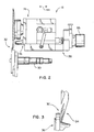
- FIG. 1 a rotary trimmer apparatus 10 for incorporating a signature cutting or trimming apparatus 12 (FIG. 2) in accordance with the present invention is shown.
- the rotary trimmer apparatus 10 can take on a variety of configurations including the illustrated apparatus 10 having a pair of trimming units 14 that are at a 90° orientation relative to each other so as to allow signatures 16 to have edge portions 18 cut off therefrom that also extend at 90° relative to each other.
- the rotary trimmer apparatus 10 has a frame 20 that supports a conveying system 22 on which a stream of signatures 16 is carried downstream.
- the signatures 16 can be folded and in overlapping orientation with adjacent signatures to provide a shingled stream of the signatures or books 16 that are to be trimmed as they are transported through the trimming units 14.
- the trimming units 14 each have at least a single set 23 of an upper knife 24 and a lower anvil 26 which are preferable mounted for rotation via respective spindle shafts 28 and 30 therefor. It is also contemplated that the position of the knife 24 and anvil 26 can be substantially reversed so the knife 24 is below the anvil 26. Also, the anvil 26 need not necessarily be rotated; however, for most types of paper and folded books 16, rotation of the anvil 26 generates the best cutting action and thus is desired. As shown in FIG. 1, opposing knife/anvil sets 23 can be provided on either side of the conveyor 22 for trimming of opposite parallel edge portions 18 from the signature books 16.
- the spindle shafts 28 and 30 are part of a rotary drive system including motors and transmission belting (not shown) that rotate the shafts in opposite directions to cause the knife 24 and anvil 26 to similarly rotate and cut signatures 16 as they pass through a cutting area 32 formed therebetween.
- the knife 24 and anvil 26 overlap each other at their lower end 34 and upper end 36, respectively, with a very small gap 37 therebetween, as best seen in FIGS. 2 and 3.
- the present cutting apparatus 12 preferably includes both an adjustment mount, generally designated 38, that allows for precision shifting of the knife 24 to a plurality of predetermined spaced positions relative to the anvil 26 and a temperature control system, generally designated 40 (FIG. 6), that, in the preferred and illustrated form thereof, is operable to keep thermal expansion of the knife spindle shaft 28 to a minimum during cutting operations, although each of the adjustment mount 38 and the temperature control system 40 can be utilized in the cutting apparatus 12 independent of the other and still substantially obtain the advantages for high quality precision trimming that each provides.
- an adjustment mount generally designated 38
- a temperature control system generally designated 40
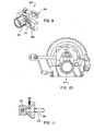
- the preferred temperature control system 40 herein is adapted to minimize the thermal expansion of the spindle shaft 28.
- the temperature control system 40 includes a temperature controlled housing 48 having an internal cavity or space 50 in which the shaft 28 extends and into which cooling medium can be directed into heat transfer relation with the knife shaft 28 to keep it from thermally expanding and changing the gap spacing 37 between the knife 24 and anvil 26 during trimming operations.
- the cooling medium can be simply discharged directly at the open shaft 28.
- cooling medium can be air that is cooled below ambient as described more fully hereinafter, it is also possible for this medium to simply be ambient air, of course recognizing that this would necessitate higher rates and volumes of such air discharged into heat transfer relation with the shaft versus those required for cooled air.
- the housing 48 can be a spindle block similar to prior spindle blocks modified to including porting 52 for a cooling medium supply line 54, as shown in FIG. 6.
- the supply line 54 directs cooling medium from a source 56 therefor into the housing internal space 50.
- the present temperature control system 40 preferably uses air as the cooling medium with the air also having preferably been reduced to a temperature below ambient temperature, e.g. approximately 50°F. Air as the cooling medium is preferred due to its low cost, ready availability and environmental friendliness.
- the temperature of the spindle shaft 28 can be kept substantially stable during trim cutting operations such as at a constant 80°F, for example, at which temperature the shaft 28 will undergo little, if any, thermal expansion along its axis 46 that would negatively affect the knife/anvil gap spacing 37 in terms of obtaining high quality cuts therewith, as previously has been described.
- the temperature control system 40 also provides for cooling of the rotary knife 24 that is focused at the area where it is needed most; that is, the temperature control system 40 also directs cool air at the knife peripheral knife cutting edge 42.
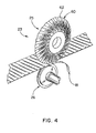
- the knife 24 is of a solid body design such as shown in FIG. 5 with the cutting edge 42 being serrated to form a large number of cutting teeth 58 integral with the knife body and extending around the periphery thereof.
- these type of solid body knives versus the knives 25 shown in FIG. 4 that have a plurality of segments 60 each with a cutting edge 62 thereof, as described in applicant's assignees U.S. Patent No. 4,840,098, there is a significant difference in the temperature rise that occurs during cutting operations.
- the segments 60 are of a very hard material such as a tungsten carbide material.
- the temperature can reach approximately 180°F during trim cutting operations while with the segmented knife 25 operating temperatures reach only approximately 120°F. It is believed that this is primarily due to the increase in the amount of cutting edge surfaces provided with the serrated cutting edge 42 of the solid body knife 24 versus the cutting edges 62 of the segmented knife 25 and the lack of heat dissipating surfaces on the solid body knife 24 as compared to those provided by the segments 60 of the knife 25.
- the spindle block housing 48 is also ported at 64 to provide an outlet for the cool air fed to the internal cavity 50 via supply line 54.
- a flexible air line or hose 66 is attached, as best seen in FIG. 6.
- the line 66 includes an outlet nozzle 68 with the line being flexible yet capable of retaining its flexed orientation so as to allow an operator to manipulate the line 66 to orient the nozzle 68 for directing cool air taken from the housing internal space 50 toward the knife serrated cutting edge 42.
- the temperature control system 40 keeps the heat generated at the cutting edge 42 during trim cutting operations to a minimum.
- the source 56 can include a vortex tube 70 utilizing technology similar to that disclosed in U.S. Patent No. 1,952,281, which is incorporated by reference herein. Utilizing a vortex tube 70 allows a feed line 72 to be attached to a shop air source for utilizing pressurized ambient temperature air, e.g. 90 psi in the range of approximately 50-70°F, with the tube 70 creating two streams of air therein including a hotter outer stream that is vented and a cooler inner stream that is fed to the supply line 54 for being directed into the spindle block housing internal space 50. As is apparent, the vortex tube 70 provides an inexpensive way for the present temperature control system 40 to provide the spindle block housing 48 with cool air.
- pressurized ambient temperature air e.g. 90 psi in the range of approximately 50-70°F
- FIGS. 9-11 show a user operated control assembly, generally designated 82, thereof.
- the control assembly 82 can be retrofit by attaching it to the spindle block housing 48, as will be described more fully hereinafter.
- the user operated control assembly 82 allows an operator to precisely control the position to which they shift the knife 24 relative to the anvil 26 so that the gap spacing 37 therebetween is known to the operator.
- control assembly 82 is mounted at the rear end portion 84 of the spindle shaft housing 48 and the operator need only turn a control knob 86 and utilize an indexing mechanism 88 adjacent the knob 86 to effect incremental shifting of the knife 24 to form predetermined known gap spacings 37 with the anvil 26, the operator will be at a position remote from the cutting area 32 when adjusting the position of the knife 24 with the present user operated control assembly 82.
- the control assembly 82 herein substantially obviates the safety concerns posed by the prior adjustment techniques that require an operator to insert a gauge in the cutting area 32, as previously described.
- control knob 86 operates a screw drive system 89 for the spindle block 48 by way of its attachment to an actuator shaft 90 as by fastener 92 at one end of the shaft 90 so that turning of the control knob 86 causes the actuator shaft 90 to rotate.
- the actuator shaft 90 threadably drives the spindle block 48 for translation via internally threaded member 94 secured to the rear end portion 84 of the spindle block housing 48.
- the member 94 includes a pair of fastener receiving through holes 96 and 98 on either side of internally threaded bore 100 with the apertures 96 and 98 aligned with corresponding threaded apertures (not shown) in the spindle block rear end 84 and the bore 100 aligned with a recessed bore 102 in the spindle block rear end portion 84.
- control assembly 82 includes an adjacent indexing mechanism 88 that is disposed between the control knob 86 and a support plate 104 for the actuator shaft 90, as can be seen in FIG. 7.
- the plate 104 rotatably supports the actuator shaft 90 extending through a central bore 106 formed in vertical wall portion 108 thereof, as shown in FIG 16.
- a bushing 110 is press-fit in the vertical wall portion bore 106 for rotatable supporting the actuator shaft 90.
- the indexing mechanism 88 includes an indexing collar 112 that is mounted on the actuator shaft 90 between the control knob 86 and the support vertical wall portion 108.
- a retainer member 113 is mounted at a predetermined axial position along the shaft 90 behind the wall portion 108 to capture the collar 112 between the support plate 104 and knob 86 against axial shifting on the shaft 90.
- the collar 112 includes a large diameter portion 114 having calibrated apertures 116 formed therein. These apertures 116 cooperate with a plunger assembly 118 so that a user has an indication of when they have reached a certain predetermined spacing 37 of the knife 24 from the anvil 26.
- the support plate 104 includes an upper rearwardly extending overhang portion 120 to which the plunger assembly 118 is mounted.
- the upper overhang portion is situated above the indexing collar 112, and particularly apertured portion 114 thereof, and has a vertical through aperture 122 in which plunger shaft 124 is biased downwardly by spring member 126, as best seen in FIG. 12. Accordingly, when the indexing collar 112 is rotated such that one of the apertures 116 is brought into alignment with the through aperture 122, the plunger shaft 124 will be biased so that its lower end 124a projects into the aligned aperture 116 to arrest further turning of the collar 112, and in this way the operator will know that they are at the indicated spaced position 37 for the knife 24 and anvil 26, as discussed further hereinafter.
- the indexing collar 112 is also provided with an integral smaller diameter portion 129 with both the portions 114 and 129 having aligned central through openings to define a through bore 130 for the collar 112 through which the actuator shaft 90 extends.
- the collar 112 is oriented on the shaft 90 so that the small diameter portion 129 projects rearwardly and is disposed between the control knob 86 and the large diameter portion 114. Accordingly, there is an annular surface 132 on the large diameter portion 114 that faces the operator as they are turning the control knob 86. To this annular surface 132, a ring label member 134 is adhered.
- the label member 134 can have a self-adhesive backing thereon and is provided with indicia 136 that when adhered to the annular surface 132 are aligned with the apertures 116 to allow an operator to read at which knife/anvil gap spacing 37 they are set. As shown, there are two sets 138a and 138b of apertures 116 with the aperture set 138a being adapted for a fine knife/anvil spacing size adjustments and the aperture set 138b adapted for coarser knife/anvil spacing size adjustments.
- the operator has significant flexibility in choosing the spacing 37 that provides the highest quality of cuts given the type of signatures 16, e.g. paperweight, thickness, number of folds, etc., being run and the anticipated operating speed of the trimmer apparatus 10.
- the operator can either make fine or course adjustments of the spacing 37.
- the apertures 116 of the aperture set 138a can be calibrated so that shifting of the knife 24 is at increments of 0.0015 inch, while the apertures 116 of the set 138b can be calibrated so that shifting of the knife 24 is at increments of 0.002 inch.
- the apertures 116 of aperture set 138a are angularly spaced at 13.5° intervals from each other, and the apertures 116 of the set 138b are angularly spaced at 18° from each other.
- the zero position of the knife/anvil set 23 needs to be initially set.
- the position at which the knife 24 is in engagement with the anvil 26 is to be the starting point for making the predetermined incremental adjustments to the spacing 37.
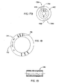
- the collar 112 is allowed to rotate relative to the actuator shaft 90 by the provision of a narrow slot 140 in the small diameter portion 129 of the collar 112 that extends normal to the bore 130.
- the slot 140 does not extend all the way through the entire diameter of the portion 129.
- the slot space 140 is very narrow, and increases the diameter of the bore 130 just enough to allow it to be in a clearance fit with the actuator shaft 90 extending therethrough.
- a releasable lock in the form of a screw clamp 142 is then operated to lock the collar 112 onto the actuator shaft 90 so that subsequent rotations thereof rotate the collar 112 therewith.
- a transverse counterbore 142 is formed in the collar portion 129 with the bore 142 spanning the slot spacing 140, as shown in FIG 17B.
- the bore 142 includes an enlarged counter recess 144 in which a spacer 146 (FIG. 19) is held.
- the spacer 146 is preferably cylindrical to allow a threaded shaft (not shown) of the screw clamp 141 to extend therethrough and for being threaded to a small diameter tapped bore section 148 on the opposite side of the slot 140 relative to the bore opening 144.
- the screw clamp 141 via lever operating arm 150 thereof in a tightening direction causes the space provided by the slot 140 to be taken up or reduced with the surfaces of the collar bore 130 tightly engaged on the portion of the actuator shaft 90 extending therethrough.
- the collar 112 With the lock 141 in its locked condition, the collar 112 will now rotate with the shaft 90 as the operator turns the control knob 86 to incrementally adjust the position of the knife 24 relative to the anvil 26 away from the zero position.
- the mylar label 134 can include arrow indicia 152 showing the operator which way to turn the knob to move the knife 24 toward or away from the anvil 26.
- the operator turns the knob 86 they will also have lifted the plunger shaft 124 so that its lower end 124a clears the zero aperture 116a or 116b, as previously discussed.
- the member 94 is fixed to the spindle block 48 at the rear end portion 84 thereof and it cooperates with the actuator shaft 90 to provide the screw drive system 89 for precision shifting of the knife 24.
- the bore 100 of the member 94 is provided with internal threads 152 that mate with external threads 154 on actuator shaft end 156, as best seen in FIG. 14.
- the shaft end 156 projects forwardly from the member 94 and into recessed bore 102 formed in the spindle block rear end portion 84, as previously described. As shown, the recessed bore 102 is formed with sufficient clearance so that the shaft end 156 can translate therein as the shaft 90 rotates.
- the member 94 is formed as a take-up member with adjustable portions 158 and 160 thereof each having the threads 152. These adjustable portions 158 and 160 are axially spaced from each other by a small gap 162 machined into the take-up member 94. This gap 162 is adjustable so as to allow the member 94 to take up the play between the threads 152 and 154.
- an adjustment member in the form of a threaded set screw 164 can be threaded through small threaded bore 166 in the member portion 158.
- the adjustment screw 164 is threaded until its distal end 166 abuts against rearwardly facing wall 160a of the take-up member portion 160.
- the adjustment screw 164 pushes the portions 158 and 160 apart from each other widening the gap 162 and taking up the play in the threads 152 and 154.
- the amount of tension on the threads 152 and 154 can be fine-tuned so as to allow threads 152 and 154 to rotate relative to each other without seizing while still substantially eliminating the backlash problems associated with a normal loose tolerance sizing of the threads 152 and 154.
- the take-up member 94 herein avoids the need to provide precision ground threads and the high expense associated therewith while still providing for precision positioning of the knife 24 relative to the anvil 26 without the aforedescribed backlash problems.
- the take-up member 94 can be of a softer material than the preferred hardened steel actuator shaft 90 such as brass so as to minimize seizing between the threads 152 and 154. With repeated usage the softer brass take-up member 94 may start to wear; however, the wear can be compensated for by simply tightening the set screw 164 to take-up any additional play in the threads 152 and 154 created by the wear of the take-up member material.
- Slide mount 170 includes a base plate or fixture 172 and a gib portion 174 at the lower end of the spindle block 48.
- the fixture plate 172 and gib portion 174 can have a dovetail fit with each other.
- the fixture plate 172 includes undercut side portions 176 and 178 on either side of the gib portion 174 which has inclined surfaces 180 and 182 in close confronting relation the facing surfaces 176a and 178a of the respective fixture plate side portions 176 and 178 to provide secure guiding of the spindle block 48 as it slides on the fixture plate 172.
- a releasable lock in the form of a screw clamp 184 is provided for either locking the spindle block 48 in fixed position relative to the fixture plate 172 or releasing it for translation thereon as earlier described.
- the screw clamp 184 is similar to the index collar screw clamp 141 and includes an operating lever 186 for turning a threaded shaft 188 attached thereto.
- the fixture plate 172 has a threaded through bore 190 formed in the plate side portion 178 and in which the shaft is received with the bore 190 opening to a notched area 192 formed in the gib surface 182.
- the notched area 192 extends for a sufficient distance in the axial direction 44 to allow the necessary shifting of the spindle block 48 in that same direction.
- the screw clamp 184 is in its unlocked condition which allows an operator to turn the control knob 86 as they lift up on the plunger assembly knob 128.
- the operator turns the operating lever 186 to advance the shaft 188 through the bore 190 until the distal shaft end 194 engages and presses against a flat surface 196 of the notched area 192.
- This pressing engagement of the shaft end 194 and surface 196 will tightly push the surfaces 176a and 180 of the fixture plate 172 and spindle block gib portion 174, respectively, against each other causing binding and locking the spindle block 48 against further axial movement in the direction 44 thus fixing the knife/anvil spacing 37 at the selected size.
- a scraper mechanism 198 is shown for keeping the rotary anvil 26, and particularly the rear disk face 200 thereof, clean and free of debris that might collect thereon during cutting operations. It is this rear disk face 200 that cooperates with the cutting edges 42 or 62 of the rotary knives 24 or 25 to generate the scissors-like cutting action on the signatures 16.
- the disk face 200 projects radially out from the disk body 202 to provide sufficient clearance for the necessary vertical overlap between the cutting edges 42 or 62 and the disk face 200 for proper scissors cutting of the signature 16.
- the scraper mechanism 198 is disposed at the lower end 204 of the anvil 26 opposite the upper end 36 thereof and remote from the cutting area 23. Debris such as ink, varnish and glue from the signatures may adhere to the disk face 200 such as due to the heat generated during cutting operations. This debris will cause an effective reduction in the size of the gap spacing 37 and can lead to premature wear of the knife edges 42 or 62. Accordingly, the scraper mechanism 198 is advantageous in that it maintains the set clearance gap 37 between the knife 24 or 25 and anvil 26.
- the scraper mechanism 198 can include a plastic scraper member 204 that is urged into engagement with the disk face 200 by way of biasing member 206.
- a housing 207 for the biasing member 206 has a side opening 207a through which a disk engaging portion 204a of the scraper member 204 extends.
- the biasing member can be in the form of a wave spring 206 that is effective to keep the plastic member 204 in scraping engagement with the disk face 200 even as the harder disk face 200, e.g. of tungsten carbide material, wears the engaging surface of the plastic scraper member 204 down. In this manner, the scraper mechanism 198 will scrape the disk face 200 clean over a large number of cycles of the rotary anvil 26 before the scraper member 204 needs to be replaced.
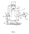
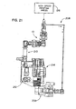
- FIG. 21 is a schematic of a room layout in which the rotary trimmer apparatus 10 can be utilized.
- a high speed printing press 216 produces printed signatures which are subjected to other processing equipment such that the rotary trimmer apparatus 10 receives a shingled stream of signatures 16 that have not been diverted by an overhead conveyor 208 to a log stacker 209.
- the trimmer apparatus 10 trims the signatures 16 with the trimmed signatures then transported to a compensating stacker 210 for either automated or manual pickup.
- a log gripper 212 can take logs of these signatures to the stacker which then delivers them to a palletizer 214.
- the rotary trimmer apparatus 10 is part of an integrated processing line for the signatures 16 post press. Accordingly, high speed operation of each of the pieces of equipment in the processing line is needed to obtain the maximum amount of throughput and allow the printing press to be run at its maximum operating speed. With the cutting apparatus 12 herein, the rotary trimmer apparatus 10 will be able to maximize the number of high quality of trim cuts of the signatures 16 it generates and thus achieve the maximum throughput of the rotary trimmer apparatus 10 for a maximum duration before knife maintenance is required.
- the present apparatus 10 and method obviate the unknown variable associated with inexact operator setup of the gap spacing 37 between the knife 24 and anvil 26 as in prior setup techniques, more precise information will be developed as to the knife life based on known variables relating to the type of signatures 16 and operating speeds where the optimum gap spacing 37 for these variables is used. More exact knife life information is beneficial for many reasons such as allowing operators to know precisely when the knife 24 will be in need of maintenance so as not to start a press run with a knife 24 that is close to the end of its useful life.
Landscapes
- Life Sciences & Earth Sciences (AREA)
- Forests & Forestry (AREA)
- Engineering & Computer Science (AREA)
- Mechanical Engineering (AREA)
- Details Of Cutting Devices (AREA)
Applications Claiming Priority (2)
| Application Number | Priority Date | Filing Date | Title |
|---|---|---|---|
| US920526 | 1997-08-29 | ||
| US09/920,526 US6692424B2 (en) | 2001-08-01 | 2001-08-01 | Rotary trimmer apparatus and method |
Publications (2)
| Publication Number | Publication Date |
|---|---|
| EP1283094A2 true EP1283094A2 (de) | 2003-02-12 |
| EP1283094A3 EP1283094A3 (de) | 2005-02-02 |
Family
ID=25443893
Family Applications (1)
| Application Number | Title | Priority Date | Filing Date |
|---|---|---|---|
| EP20020016918 Withdrawn EP1283094A3 (de) | 2001-08-01 | 2002-07-31 | Vorrichtung zum Trimmen mit einem Rotationswerkzeug |
Country Status (2)
| Country | Link |
|---|---|
| US (1) | US6692424B2 (de) |
| EP (1) | EP1283094A3 (de) |
Cited By (6)
| Publication number | Priority date | Publication date | Assignee | Title |
|---|---|---|---|---|
| DE10335212A1 (de) * | 2003-08-01 | 2005-02-17 | Hans Ziller Gmbh & Co. Kg | Schneidevorrichtung zum Schneiden von Verstärkungseinlagen enthaltenden Bändern |
| EP1724077A1 (de) * | 2005-05-17 | 2006-11-22 | bielomatik Leuze GmbH + Co KG | Längsschneidvorrichtung mit einer Zustelleinrichtung für Ober- und Untermesser |
| EP1952956A1 (de) * | 2007-02-02 | 2008-08-06 | Müller Martini Holding AG | Vorrichtung zum Schneiden eines aus Druckprodukten gebildeten Schuppenstroms |
| FR2913626A1 (fr) * | 2007-03-16 | 2008-09-19 | Recmi Ind Sa | Machine a couteaux rotatifs equipee d'un detecteur de contact des lames |
| WO2010071556A1 (en) | 2008-12-15 | 2010-06-24 | Ecolean Research & Development A/S | Device for removing an end closure |
| ITUA20161489A1 (it) * | 2016-03-10 | 2017-09-10 | Gd Spa | Testa di taglio per il taglio di spezzoni a forma di bacchetta in macchine per la produzione di articoli da fumo. |
Families Citing this family (11)
| Publication number | Priority date | Publication date | Assignee | Title |
|---|---|---|---|---|
| US8286539B2 (en) | 2002-11-01 | 2012-10-16 | Black & Decker Inc. | Tile saw |
| JP2004195569A (ja) * | 2002-12-17 | 2004-07-15 | Fuji Xerox Co Ltd | 用紙処理装置、およびカッタユニット |
| EP1510288B1 (de) * | 2003-08-28 | 2007-02-14 | Müller Martini Holding AG | Verfahren zum Schleifen der Messer einer Rotationsschneidemaschine sowie Rotationsschneider zur Durchführung des Verfahrens |
| EP1827527B1 (de) * | 2004-12-06 | 2016-08-24 | Cook Incorporated | Aufblasbare okklusionsvorrichtungen, verfahern und systeme |
| WO2007112286A2 (en) | 2006-03-24 | 2007-10-04 | Auxilium Pharmaceuticals, Inc. | Stabilized compositions containing alkaline labile drugs |
| DE102007019864B4 (de) * | 2007-04-23 | 2011-06-22 | KOENIG & BAUER Aktiengesellschaft, 97080 | Längsperforationsvorrichtungen für eine Rollenrotationsdruckmaschine mit mindestens einem Perforiermesser |
| US8291799B2 (en) * | 2007-06-29 | 2012-10-23 | Quad/Graphics, Inc. | Adjustable trimming assembly |
| US8616103B2 (en) * | 2007-10-22 | 2013-12-31 | Formax, Inc | Knife blade retraction mechanism for a food article slicing machine |
| US8056458B2 (en) * | 2008-08-20 | 2011-11-15 | Wenger Manufacturing, Inc. | Extruder cut-off knife assembly having remote adjustment mechanism |
| CN113520036B (zh) * | 2021-08-11 | 2022-10-11 | 安徽友川刷业有限公司 | 一种植毛生产线可多尺寸修剪的毛刷修整装置 |
| WO2024197272A2 (en) * | 2023-03-23 | 2024-09-26 | Pneu-Tools, Inc. | Continuous roll molding system and method; frangible cap strip and method of making using continuous roll molding |
Family Cites Families (19)
| Publication number | Priority date | Publication date | Assignee | Title |
|---|---|---|---|---|
| US1952281A (en) | 1931-12-12 | 1934-03-27 | Giration Des Fluides Sarl | Method and apparatus for obtaining from alpha fluid under pressure two currents of fluids at different temperatures |
| US2755989A (en) * | 1952-10-01 | 1956-07-24 | Richard W Coward | Cooling system for shafts and bearings |
| US3297239A (en) * | 1965-04-29 | 1967-01-10 | Fly Ash Arrestor Corp | Cooling system for shafts and the like |
| US3460418A (en) * | 1967-09-05 | 1969-08-12 | Philip Morris Inc | Cleaner device for cleaning residue from the cutting edge of a rotary disc type cutter |
| US3718064A (en) * | 1971-01-21 | 1973-02-27 | Steel Corp | Apparatus for adjustment of side trimmer knife |
| FR2252006A5 (de) * | 1973-10-30 | 1975-06-13 | Etudes De Machines Speciales | |
| US3915445A (en) * | 1974-01-18 | 1975-10-28 | Donnelley & Sons Co | Method of and apparatus for forming a printed web into stitched signatures |
| US3886833A (en) * | 1974-05-01 | 1975-06-03 | Elworthy & Co Ltd | Apparatus to effect remote automatic positioning of web slitter |
| DE2821956C2 (de) * | 1978-05-19 | 1985-01-03 | E.C.H. Will (Gmbh & Co), 2000 Hamburg | Messerhalter für Längsschnittstationen an Papierverarbeitungsmaschinen |
| JPS55120927A (en) * | 1979-03-07 | 1980-09-17 | Tani Seikiyo Kk | Circular saw with guide groove cut in inside surface, and device using the same |
| JPS5776320A (en) * | 1980-10-30 | 1982-05-13 | Nakamuratome Seimitsu Kogyo Kk | Cooling device for bearing part |
| DE3146116C2 (de) * | 1981-11-20 | 1985-10-10 | Dr. Otto C. Strecker Kg, 6102 Pfungstadt | Messerhalter für Längsschneider |
| DE3219774A1 (de) * | 1982-05-26 | 1983-12-01 | Dr. Otto C. Strecker Kg, 6102 Pfungstadt | Staubabsaugeinrichtung fuer laengsschneider |
| US4784030A (en) * | 1984-11-23 | 1988-11-15 | The Uniroyal Goodrich Tire Company | Slitter apparatus |
| US5197364A (en) * | 1990-04-02 | 1993-03-30 | Grapha-Holding Ag | Method of and apparatus for trimming lateral marginal portions of sheets in a stream of partly overlapping sheets |
| US5373766A (en) * | 1992-05-06 | 1994-12-20 | Monarch Machine Tool Co., Stamco Division | Slitter knife holder |
| GB9414803D0 (en) * | 1994-07-22 | 1994-09-14 | Lamberton & Co Ltd | Inspection system |
| BR9503770A (pt) * | 1994-08-31 | 1996-04-16 | Goodyear Tire & Rubber | Conjunto de corte rotativo de alta velovidade para cortar folhas de materiais elastoméricos método de corte rotativo de alta velocidade de uma folha de material elastomérico e método para substituir uma sapata e um inserto de sapata em uma aplicação envolvendo o corte rotativo de alta velocidade de uma folha de material elastomérico |
| US6202525B1 (en) * | 1998-02-25 | 2001-03-20 | Johns Manville International, Inc. | Chopping apparatus |
-
2001
- 2001-08-01 US US09/920,526 patent/US6692424B2/en not_active Expired - Fee Related
-
2002
- 2002-07-31 EP EP20020016918 patent/EP1283094A3/de not_active Withdrawn
Cited By (12)
| Publication number | Priority date | Publication date | Assignee | Title |
|---|---|---|---|---|
| DE10335212A1 (de) * | 2003-08-01 | 2005-02-17 | Hans Ziller Gmbh & Co. Kg | Schneidevorrichtung zum Schneiden von Verstärkungseinlagen enthaltenden Bändern |
| EP1724077A1 (de) * | 2005-05-17 | 2006-11-22 | bielomatik Leuze GmbH + Co KG | Längsschneidvorrichtung mit einer Zustelleinrichtung für Ober- und Untermesser |
| DE102005023720A1 (de) * | 2005-05-17 | 2006-11-23 | Bielomatik Leuze Gmbh + Co.Kg | Längsschneidvorrichtung für kontinuierlich geförderte Materialbahnen und Verfahren hierfür |
| EP1952956A1 (de) * | 2007-02-02 | 2008-08-06 | Müller Martini Holding AG | Vorrichtung zum Schneiden eines aus Druckprodukten gebildeten Schuppenstroms |
| US8011280B2 (en) | 2007-02-02 | 2011-09-06 | Mueller Martini Holding Ag | Rotary cutter for trimming printed products conveyed in an overlapping flow |
| FR2913626A1 (fr) * | 2007-03-16 | 2008-09-19 | Recmi Ind Sa | Machine a couteaux rotatifs equipee d'un detecteur de contact des lames |
| WO2010071556A1 (en) | 2008-12-15 | 2010-06-24 | Ecolean Research & Development A/S | Device for removing an end closure |
| CN102245476A (zh) * | 2008-12-15 | 2011-11-16 | 爱克林研发股份公司 | 用于移除端封闭部的装置 |
| RU2478068C2 (ru) * | 2008-12-15 | 2013-03-27 | Эколин Рисерч Энд Девилопмент А/С | Устройство для удаления концевой укупорочной части |
| CN102245476B (zh) * | 2008-12-15 | 2013-10-30 | 爱克林公司 | 用于移除端封闭部的装置 |
| ITUA20161489A1 (it) * | 2016-03-10 | 2017-09-10 | Gd Spa | Testa di taglio per il taglio di spezzoni a forma di bacchetta in macchine per la produzione di articoli da fumo. |
| EP3216355A1 (de) * | 2016-03-10 | 2017-09-13 | G.D. S.p.A | Schneidevorrichtung für stabförmige rauckartikeln |
Also Published As
| Publication number | Publication date |
|---|---|
| EP1283094A3 (de) | 2005-02-02 |
| US6692424B2 (en) | 2004-02-17 |
| US20030024424A1 (en) | 2003-02-06 |
Similar Documents
| Publication | Publication Date | Title |
|---|---|---|
| US6692424B2 (en) | Rotary trimmer apparatus and method | |
| CN113799190B (zh) | 使用切割装置来减少标签浪费的方法 | |
| US4962683A (en) | Rotary cutter apparatus | |
| EP0836918A1 (de) | Zerspaner mit austauschbaren Schlichtmessern | |
| GB2122941A (en) | Method for slitting elongated rolls of web material | |
| EP1110683B1 (de) | Verfahren sowie Vorrichtung zur Wiederherstellung des Gummituchzylinders einer Rotationsstanzmaschine für die Herstellung von Faltschachteln | |
| US5596918A (en) | Sports card slitting device and method | |
| EP0505508B1 (de) | Längsschneideeinrichtung für wellpappe u.dgl. | |
| US4030394A (en) | Device for cutting through a pile of sheets with a revolving blade | |
| US4501177A (en) | Edge trimming and scrap disposal system | |
| US4583459A (en) | Sheet-fed printing machine with means for cutting sheets longitudinally | |
| EP0701886A2 (de) | Verfahren und Vorrichtung zum Hochgeschwindigkeitsschneiden von elastomerischen Werkstoffen | |
| US4799414A (en) | Rotary cutter apparatus | |
| US3706252A (en) | Book cut-off saw | |
| BE1009187A5 (fr) | Systeme de coupe tangentielle automatique. | |
| EP1187785B1 (de) | Kraftverstellbarer drehender apparat zum bearbeiten von bahnen | |
| US3831480A (en) | Rotary cutter-slitter for high speed bursting apparatus | |
| CN212635873U (zh) | 一种连续型瓦楞纸板切割装置 | |
| US5325753A (en) | Cutting blade holder assembly | |
| US7901271B2 (en) | Shimless dual arbor scrap chopper | |
| US7083503B2 (en) | Method for sharpening the knife of a rotary trimmer and a rotary trimmer for realizing the method | |
| US8783150B2 (en) | Device for trimming a print product | |
| EP0552396B1 (de) | Schneidvorrichtung | |
| CN219929197U (zh) | 一种切割宽幅便于调节的薄膜分切机 | |
| US20260077530A1 (en) | Cutting heads, cutting machines equipped therewith, and methods of operation |
Legal Events
| Date | Code | Title | Description |
|---|---|---|---|
| PUAI | Public reference made under article 153(3) epc to a published international application that has entered the european phase |
Free format text: ORIGINAL CODE: 0009012 |
|
| AK | Designated contracting states |
Designated state(s): AT BE BG CH CY CZ DE DK EE ES FI FR GB GR IE IT LI LU MC NL PT SE SK TR |
|
| AX | Request for extension of the european patent |
Extension state: AL LT LV MK RO SI |
|
| PUAL | Search report despatched |
Free format text: ORIGINAL CODE: 0009013 |
|
| AK | Designated contracting states |
Kind code of ref document: A3 Designated state(s): AT BE BG CH CY CZ DE DK EE ES FI FR GB GR IE IT LI LU MC NL PT SE SK TR |
|
| AX | Request for extension of the european patent |
Extension state: AL LT LV MK RO SI |
|
| STAA | Information on the status of an ep patent application or granted ep patent |
Free format text: STATUS: THE APPLICATION IS DEEMED TO BE WITHDRAWN |
|
| 18D | Application deemed to be withdrawn |
Effective date: 20050201 |