EP1283145A2 - Poussette pliable en trois - Google Patents
Poussette pliable en trois Download PDFInfo
- Publication number
- EP1283145A2 EP1283145A2 EP02017952A EP02017952A EP1283145A2 EP 1283145 A2 EP1283145 A2 EP 1283145A2 EP 02017952 A EP02017952 A EP 02017952A EP 02017952 A EP02017952 A EP 02017952A EP 1283145 A2 EP1283145 A2 EP 1283145A2
- Authority
- EP
- European Patent Office
- Prior art keywords
- horizontal middle
- connecting bar
- stroller
- rear connecting
- end sections
- Prior art date
- Legal status (The legal status is an assumption and is not a legal conclusion. Google has not performed a legal analysis and makes no representation as to the accuracy of the status listed.)
- Withdrawn
Links
Images


Classifications
-
- B—PERFORMING OPERATIONS; TRANSPORTING
- B62—LAND VEHICLES FOR TRAVELLING OTHERWISE THAN ON RAILS
- B62B—HAND-PROPELLED VEHICLES, e.g. HAND CARTS OR PERAMBULATORS; SLEDGES
- B62B7/00—Carriages for children; Perambulators, e.g. dolls' perambulators
- B62B7/04—Carriages for children; Perambulators, e.g. dolls' perambulators having more than one wheel axis; Steering devices therefor
- B62B7/06—Carriages for children; Perambulators, e.g. dolls' perambulators having more than one wheel axis; Steering devices therefor collapsible or foldable
-
- B—PERFORMING OPERATIONS; TRANSPORTING
- B62—LAND VEHICLES FOR TRAVELLING OTHERWISE THAN ON RAILS
- B62B—HAND-PROPELLED VEHICLES, e.g. HAND CARTS OR PERAMBULATORS; SLEDGES
- B62B9/00—Accessories or details specially adapted for children's carriages or perambulators
- B62B9/20—Handle bars; Handles
-
- B—PERFORMING OPERATIONS; TRANSPORTING
- B62—LAND VEHICLES FOR TRAVELLING OTHERWISE THAN ON RAILS
- B62B—HAND-PROPELLED VEHICLES, e.g. HAND CARTS OR PERAMBULATORS; SLEDGES
- B62B7/00—Carriages for children; Perambulators, e.g. dolls' perambulators
- B62B7/04—Carriages for children; Perambulators, e.g. dolls' perambulators having more than one wheel axis; Steering devices therefor
- B62B7/06—Carriages for children; Perambulators, e.g. dolls' perambulators having more than one wheel axis; Steering devices therefor collapsible or foldable
- B62B7/08—Carriages for children; Perambulators, e.g. dolls' perambulators having more than one wheel axis; Steering devices therefor collapsible or foldable in the direction of, or at right angles to, the wheel axis
-
- B—PERFORMING OPERATIONS; TRANSPORTING
- B62—LAND VEHICLES FOR TRAVELLING OTHERWISE THAN ON RAILS
- B62B—HAND-PROPELLED VEHICLES, e.g. HAND CARTS OR PERAMBULATORS; SLEDGES
- B62B2205/00—Hand-propelled vehicles or sledges being foldable or dismountable when not in use
- B62B2205/003—Hand-propelled vehicles or sledges being foldable or dismountable when not in use with actuation mechanisms which drive the folding or unfolding operation
-
- B—PERFORMING OPERATIONS; TRANSPORTING
- B62—LAND VEHICLES FOR TRAVELLING OTHERWISE THAN ON RAILS
- B62B—HAND-PROPELLED VEHICLES, e.g. HAND CARTS OR PERAMBULATORS; SLEDGES
- B62B2205/00—Hand-propelled vehicles or sledges being foldable or dismountable when not in use
- B62B2205/02—Hand-propelled vehicles or sledges being foldable or dismountable when not in use foldable widthwise
-
- B—PERFORMING OPERATIONS; TRANSPORTING
- B62—LAND VEHICLES FOR TRAVELLING OTHERWISE THAN ON RAILS
- B62B—HAND-PROPELLED VEHICLES, e.g. HAND CARTS OR PERAMBULATORS; SLEDGES
- B62B2205/00—Hand-propelled vehicles or sledges being foldable or dismountable when not in use
- B62B2205/18—Geared articulations
-
- B—PERFORMING OPERATIONS; TRANSPORTING
- B62—LAND VEHICLES FOR TRAVELLING OTHERWISE THAN ON RAILS
- B62B—HAND-PROPELLED VEHICLES, e.g. HAND CARTS OR PERAMBULATORS; SLEDGES
- B62B2205/00—Hand-propelled vehicles or sledges being foldable or dismountable when not in use
- B62B2205/20—Catches; Locking or releasing an articulation
- B62B2205/22—Catches; Locking or releasing an articulation remotely controlled, e.g. from the handlebar
-
- B—PERFORMING OPERATIONS; TRANSPORTING
- B62—LAND VEHICLES FOR TRAVELLING OTHERWISE THAN ON RAILS
- B62B—HAND-PROPELLED VEHICLES, e.g. HAND CARTS OR PERAMBULATORS; SLEDGES
- B62B7/00—Carriages for children; Perambulators, e.g. dolls' perambulators
- B62B7/04—Carriages for children; Perambulators, e.g. dolls' perambulators having more than one wheel axis; Steering devices therefor
- B62B7/06—Carriages for children; Perambulators, e.g. dolls' perambulators having more than one wheel axis; Steering devices therefor collapsible or foldable
- B62B7/08—Carriages for children; Perambulators, e.g. dolls' perambulators having more than one wheel axis; Steering devices therefor collapsible or foldable in the direction of, or at right angles to, the wheel axis
- B62B7/086—Carriages for children; Perambulators, e.g. dolls' perambulators having more than one wheel axis; Steering devices therefor collapsible or foldable in the direction of, or at right angles to, the wheel axis becoming smaller in all three dimensions
-
- Y—GENERAL TAGGING OF NEW TECHNOLOGICAL DEVELOPMENTS; GENERAL TAGGING OF CROSS-SECTIONAL TECHNOLOGIES SPANNING OVER SEVERAL SECTIONS OF THE IPC; TECHNICAL SUBJECTS COVERED BY FORMER USPC CROSS-REFERENCE ART COLLECTIONS [XRACs] AND DIGESTS
- Y10—TECHNICAL SUBJECTS COVERED BY FORMER USPC
- Y10T—TECHNICAL SUBJECTS COVERED BY FORMER US CLASSIFICATION
- Y10T403/00—Joints and connections
- Y10T403/32—Articulated members
- Y10T403/32254—Lockable at fixed position
- Y10T403/32262—At selected angle
- Y10T403/32319—At selected angle including pivot stud
- Y10T403/32409—Members locked in axial alignment
Definitions
- the present invention relates to a stroller foldable in three provided with a folding part operating mechanism.
- the user needs to take the hands off the handle and to grip opposite end parts of the handle or the armrests, the user needs to use both the hands for folding the stroller, which is difficult to do with the arms holding a baby.
- the stroller needs to be provided with many joints to reduce resistance against the folding movement of the parts of the stroller. Those joints reduce the rigidity of a main structure of the stroller, lessen the sensation of operation and make it difficult for the user to feel the sensation of locking.
- the present invention has been made in view of the foregoing problems and it is therefore an object of the present invention to provide a stroller foldable in three comprising: a handle having a horizontal middle part, and two side pipes connected to the opposite ends of the horizontal middle part so as to be turnable about axes perpendicular to the axis of the horizontal middle part, respectively; and a folding part operating mechanism incorporated into the handle; wherein the folding part operating mechanism turns the two side pipes relative to the horizontal middle part.
- the horizontal middle part is capable of turning about its axis
- the folding part operating mechanism has gear trains interposed between the horizontal middle part and the two side pipes, respectively, and interlocking the horizontal middle part and the side pipes.
- each of the gear trains includes a first bevel gear mounted on the horizontal middle part, and a second bevel gear mounted on the side pipe.
- the folding stroller foldable in three according to the present invention is provided with locking members for maintaining the stroller in an unfolded state, and a release mechanism for releasing the locking members, incorporated into the horizontal middle part.
- the release mechanism includes sliding members with projections disposed for sliding in the horizontal middle part and connected to the locking members by wires, a cam member provided with slots respectively engaged with the projections of the sliding members and capable of being moved in opposite directions perpendicular to the axis of the horizontal middle part, and a release lever for operating the cam member for movement in the opposite directions.
- the slots are inclined to the axis of the horizontal middle part, the sliding members can be to slide in the horizontal middle part by moving the cam member in the opposite directions perpendicular to the axis of the horizontal middle part by the release lever to release the locking members.
- the cam member has an inclined wall declining toward the release lever, an end part of the release lever is pressed against the inclined wall of the cam member to move the cam member in a direction perpendicular to the axis of the horizontal middle part.
- the folding part operating mechanism has tubular structures interposed between the side pipes and the horizontal middle part, extending along turning axes of the side pipes, and provided with helical guide grooves formed in their inner surfaces, respectively, the horizontal middle part is capable of sliding relative to the tubular structures along the axes of the tubular structures, the horizontal middle part is provided with projections respectively engaged in the helical guide grooves of the tubular structures, and the projections of the horizontal middle part are to slide along the helical guide grooves of the tubular structures by sliding the horizontal middle part relative to the tubular structures to turn the side pipes together with the corresponding tubular structures relative to the horizontal middle part.
- each of the tubular structures consists of coaxial inner and outer tubes capable of turning relative to each other, openings for passing the horizontal middle part are formed in the inner and outer tubes, respectively, the helical guide groove is formed in the inner tube, and the inner tube and the outer tube are connected by a coil spring.
- retractable bolts are supported on the opposite end parts of the horizontal middle part, first recesses in which the retractable bolts engage when the handle is unfolded to hold the handle in an unfolded state are formed in upper ends of openings formed in the tubular structures, respectively, and second recesses in which the retractable bolts engage when the handle is folded to hold the handle in a folded state are formed in lower ends of the openings formed in the tubular structures, respectively.
- the stroller foldable in three according to the present invention further includes locking members for maintaining the stroller in an unfolded state, and a release mechanism, for releasing the locking members, incorporated into the horizontal middle part, and provided with a release lever interlocked with retractable bolts.
- the horizontal middle part is turnable about its axis
- the folding part operating mechanism includes two gears supported for turning in the horizontal middle part, an operating lever for turning the two gears, and shape memory springs, wherein each of the shape memory springs has one end connected to the corresponding gear and the other end lying in and fastened to the corresponding side pipe.
- a stroller foldable in three according to the present invention includes right and left rear legs, and a rear connecting bar connecting the rear legs, wherein the rear connecting bar has a middle section, and two end sections pivotally connected to the opposite ends of the middle section, respectively, a foot-operated folding part operating mechanism is mounted on the rear connecting bar, and the two end sections are turned relative to the middle section by the folding part operating mechanism.
- the foot-operated folding part operating mechanism is combined with the middle section and the two end sections of the rear connecting bar.
- the foot-operated folding part operating mechanism includes a tubular member provided on the middle section and holding first bevel gears on its opposite ends, and second bevel gears respectively connected to the two end sections; and the second bevel gears are engaged with the first bevel gears.
- an operating lever projects outward from the tubular member, and a locking bolt for locking the tubular member relative to the middle section of the rear connecting bar is placed slidably in the operating lever.
- the operating lever is pivotally supported on the tubular member for forward and backward turning through a predetermined angle
- a locking bolt provided with a guide pin at its outer end is placed movably in the operating lever
- V-shaped guide grooves diverging toward the free end of the operating lever are formed in the inner surface of the operating lever.
- an unlocking member is pivotally connected to an outer end part of the operating lever, and the unlocking member is connected to the locking bolt by a link.
- the second bevel gears are connected to the corresponding end sections of the rear connecting bar by coil springs having axes aligned with turning axes of the end sections of the rear connecting bar, respectively.
- plates are attached to the second bevel gears, respectively, and a spring is extended between the plates so as to urge the plates together with the end sections of the rear connecting bar in a folding direction.
- the stroller foldable in three according to the present invention is provided with right and left front legs, and a front connecting bar connecting the front legs, wherein the front connecting bar has a middle section, and two end sections pivotally connected to the opposite ends of the middle section, respectively, and a spring is extended between the two end sections of the front connecting bar so as to urge the end sections in a folding direction.
- the a pulley provided with an operating lever is mounted for turning on the middle section of the rear connecting bar, first ends of two wires are fixed to the pulley, and second ends of the wires are guided by guide members and connected to the end sections of the rear connecting bar, respectively.
- a tubular member provided with laterally symmetrical, inclined slots is mounted on the middle section of the rear connecting bar, two connecting rods are supported so as to move along the middle section of the rear connecting bar, first ends of the connecting rods are connected to the end sections of the rear connecting bar, respectively, and projections connected to second ends of the connecting rods are engaged in the inclined slots of the tubular member, respectively.
- an operating rod is formed integrally with one of the end sections of the rear connecting bar so as to extend from the same, and a middle part of the operating rod is connected to a middle part of the other end section by a link.
- FIG. 1 A first embodiment according to the present invention is shown in Figs. 1, 19 and 20.
- General construction of a folding stroller 10 in the first embodiment will be described with reference to Figs. 19 and 20 showing the stroller 10 in perspective views.
- the stroller 10 has two front legs (right and left front legs) 12 provided with front wheels 11, two rear legs (right and left rear legs) 14 provided with rear wheels 13, a substantially U-shaped handle 15, two armrests (right and left armrests) 16, and a detachable guard arm 17 extended between the armrests 16.
- the handle 15 has right and left side pipes 18.
- Rear ends of the armrests 16 are pivotally connected to parts near the lower ends of the right and the left side pipe 18, respectively.
- the upper end parts of the front legs 12 are pivotally joined to front end part of the armrests 16, respectively.
- Upper end parts of the rear legs 14 are pivotally joined to middle parts of the armrests 16, respectively.
- the right and the left front leg 12 are connected by a front connecting bar 21, and the right and the left rear leg 14 are connected by a rear connecting bar 22.
- Front ends of side connecting bars 23 are pivotally joined to middle parts of the front legs 12, respectively, and the rear ends of the side connecting bars 23 are pivotally joined together with the brackets 19 to the lower end parts of the side pipes 18, respectively.
- Middle parts of the side connecting bars 23 are connected by an upper connecting bar 24.
- the locking members 20 put on the lower end of the side pipes 18 are engaged with the upper locking parts of the brackets 19 to hold the stroller 10 in the unfolded state for use.
- a folding part operating mechanism 25 combined with the handle 15 is operated to disengage the locking members 20 from the brackets 19, the armrests 16 and the side connecting bars 23 are allowed to turn upward on the pivotal joints to the side pipes 18, so that the front legs 12 and the rear legs 14 can be folded so as to extend substantially parallel to each other to facilitate carrying the stroller 10.
- the handle 15, the front connecting bar 21, the rear connecting bar 22 and the upper connecting bar 24 have middle parts each provided with two joints at its opposite ends, and the joints at the opposite ends of the middle parts are included in two vertical planes, respectively.
- the handle 15, the front connecting bar 21, the rear connecting bar 22 and the upper connecting bar 24 are foldable.
- the side pipes 18 are moved forward after folding the front legs 12 and the rear legs 14 so as to extend substantially parallel, the respective end parts of the handle 15, the front connecting bar 21, the rear connecting bar 22 and the upper connecting bar 24 are bent forward. Consequently, the stroller 10 can be compactly folded in three as shown in Fig. 20.
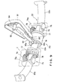
- the folding part operating mechanism 25 will be described with reference to Fig. 1.
- the handle 15 of the stroller 10 has the two side pipes 18, and a horizontal middle part 30 extended between the two side pipes 18.
- the side pipes 18 are joined to the opposite ends of the horizontal middle part 30 so as to be turnable about axes perpendicular to the axis of the horizontal middle part 30.
- first bevel gears 31 are mounted on the opposite end parts of the horizontal middle part 30 of the handle 15, respectively.
- the first bevel gears 31 are housed in joint casings 32.
- Opposite end parts of the horizontal middle part 30 are supported for turning about an axis by the joint casings 32.
- Shafts 33 are housed in and supported on the joint casings 32 for turning about axes perpendicular to the axis of the horizontal middle part 30.
- Second bevel gears 34 are fixedly mounted on the shafts 33 so as to engage with the first bevel gears 31, respectively.
- Pipe connectors 35 are connected to middle parts of the shafts 33 so as to project perpendicularly to the axes of the shafts 33, respectively.
- the pipe connectors 35 extend outside through openings 36 formed in the joint casings 32, respectively, and horizontal upper end parts formed in a shape resembling the inverted letter L of the side pipes 18 are fixed to the pipe connectors 35, respectively.
- the openings 36 of the joint casings 32 extend circumferentially in an angular range of about 90°.
- the pipe connectors 35 connected to the horizontal upper end parts of the side pipes 18 can be set in an unfolded state with their axes aligned with the axis of the horizontal middle part 30 or a folded state with their axes extended perpendicularly to the axis of the horizontal middle part 30.
- a housing 37 included in the folding part operating mechanism 25 is fastened to the horizontal middle part 30 with a fastening pin 38.
- the horizontal middle part 30 turns in the direction of the arrow indicated in Fig. 1. Consequently, the first bevel gears 31 drive the second bevel gears 34 for turning in the directions of the arrows, respectively, and the horizontal upper end parts of the right and the left side pipe 18 are turned from positions corresponding to the folded state, where the horizontal upper end parts of the right and the left side pipes 18 are perpendicular to the horizontal middle part 30 as shown in Fig. 1, to positions corresponding to the unfolded sate, where the horizontal upper end parts of the right and the left side part 18 are aligned with the horizontal middle part 30, respectively.
- the first bevel gears 31 and the second bevel gears 32 form gear trains.
- the gear trains and the housing 37 constitute the folding part operating mechanism 25.
- a release mechanism 39a is formed in the housing 37.
- the release mechanism 39a disengages the locking members 20 slidably mounted on the lower end parts of the side pipes 18 from the brackets 19, respectively.
- Two sliders (right and left sliders) 39 are placed in the horizontal middle part 30 and are connected by wires 40 to the locking members 20 mounted on the right and the left side pipe 18, respectively.
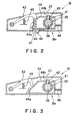
- the horizontal middle part 30 is provided with two slots (right and left slots) 41 extending along the axis of the horizontal middle part 30. Projections 42 projecting from the sliders 39 are engaged in the slots 41, respectively, as shown in Fig. 2 to guide the sliders 39 for axial movement in the horizontal middle part 30.
- a release lever 43 is supported pivotally in the housing 37.
- a cam member 44 is placed in the housing 37 so as to be moved in directions perpendicular to the axis of the horizontal middle part 30 by turning the release lever 43.
- the release lever 43 is pushed upward by a spring 45.
- the cam member 44 has an inclined wall 44a rising toward the horizontal middle part 30, and a top wall overlying the horizontal middle part 30 and provided with two oblique slots 44b inclined to the axis of the horizontal middle part 30.
- the projections 42 projecting from the sliders 39 are engaged in the oblique slots 44b, respectively.
- the cam member 44 is pushed toward the release lever 43 by a spring 46.
- a safety lever 47 having an L-shaped cross section is placed in the housing 37 on the side of the inclined wall 44a of the cam member 44, i.e., the side opposite of the horizontal middle part 30 with respect to the cam member 44, so as to be movable in directions perpendicular to the axis of the horizontal middle part 30,.
- the safety lever 47 is pushed toward the cam member 44 by a spring, not shown, such that the top of the safety lever 47 is in contact with the release lever 43 to prevent the release lever 43 from being depressed.
- An operating button 48 projecting from the lower surface of the safety lever 47 projects outside from the housing 37 through an opening 39 formed in the housing 37.
- the user is able to fold and unfold the stroller 10 simply by turning the nearby housing 37 without ever letting go of the housing 37.
- the safety lever 47 may be omitted as shown in Fig. 3.
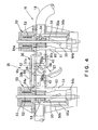
- FIG. 4 and 5 showing the second embodiment of the present invention
- vertical tubular structures 50 are fastened to horizontal upper end parts of right and left side pipes 18 included in a handle 15. Openings 51 are formed in opposite parts of the tubular structures 50, respectively, and opposite end parts of a horizontal middle part 30 included in the handle 15 are inserted through the openings 51 in the tubular structures 50, respectively, to connect the right and the left tubular structures 50.
- a vertical guide rod 52 is extended in each of the tubular structures 50, and the end part of the horizontal middle part 30 is put closely on the guide rod 52.
- the horizontal middle part 30 is able to move vertically along the guide rods 52.
- the opening 51 of each tubular structure 50 is formed such that the horizontal middle part 30 is able to move vertically, and each tubular structure 50 is able to turn on the guide rod 52 relative to the horizontal middle part 30 in an angular range of about 90°.
- Each tubular structure 50 consists of an outer tube 50b and an inner tube 50a coaxially inserted in the outer tube 50b and provided with a helical groove 55.
- the inner tube 50a and the outer tube 50b are interlocked by a coil spring 53 coaxial with the inner tube 50a and the outer tube 50b.
- the inner tube 50a turns the outer tube 50b through the coil spring 53.
- the horizontal middle part 30 is inserted through the outer tube 50b in the inner tube 50a.
- a projection 54 projecting in parallel to the axis of the horizontal middle part 30 from each end of the horizontal middle part 30 is engaged in the helical groove 55 of the inner tube 50a.
- the tubular structures 50 each including the inner tube 50a and the outer tube 50b, and the horizontal middle part 30 constitute a folding part operating mechanism 25.
- the inner tubes 50a and the outer tubes 50b are turned on the guide rods 52 by the agency of the helical grooves 55 of the inner tubes 50a and the projections 54 engaged in the helical grooves 55, respectively.
- the inner tubes 50a and the outer tubes 50b are set in the unfolded state, where the horizontal upper end parts of the right and the left side pipe 18 are aligned with the horizontal middle part 30 as shown in Fig. 4, or in the folded state, where the horizontal upper end parts of the right and the left side pipe 18 extend perpendicularly to the horizontal middle part 30 as shown in Fig. 5.
- the horizontal middle part 30 is provided with a release mechanism 56a.
- the release mechanism 56a disengages locking members 20 slidably mounted on the lower end parts of the side pipes 18 (Fig. 19) from brackets 19 pivotally joined to the side pipes 18, respectively.
- the locking mechanism 56a is for maintaining the stroller in the unfolded state or in the folded state.
- the horizontal middle part 30 includes a frame 30a of a metal having a U-shaped cross section, and cases 30b covering the opposite sides of the frame 30a.
- a pulley 56 is disposed in the horizontal middle part 30. Wires 40 are connected to the pulley 56.
- Each of the wires 50 has one end connected to the pulley 56 and the other end connected to the locking member 20 slidably mounted on the side pipe 18.
- the pulley 56 is a component of the release mechanism 56a.
- An operating lever 57 is formed integrally with the pulley 56.
- the pulley 56 and the operating lever 57 are supported on a shaft 58 extending perpendicularly to the axis of the horizontal middle part 30.
- the operating lever 57 projects downward from the cases 30b.
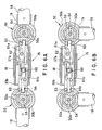
- a pinion 60 is supported for turning on a substantially central part of the upper wall of the frame 30a.
- Two racks 61a and 61b are disposed on the opposite sides of the pinion 60, are engaged with the pinion 60, and are supported for lateral sliding on the frame 30a.
- a U-shaped frame 62 protrudes from the rack 61a toward the pulley 56 as indicated by broken lines in Figs. 6A and 6B so as to engage with the tip 57a of the operating lever 57.
- locking bars 63 extend vertically from the outer ends of the racks 61a and 61b, respectively.
- the locking bars 63 are able to engage selectively in recesses formed in the tubular structures 50, respectively.
- An upper recess 64a and a lower recess 64b are formed in the upper end and the lower end, respectively, of the opening 51 formed in the inner tube 50a and the outer tube 50b of each tubular structure 50.
- the locking bar 63 engages in the upper recess 64a when the handle 15 is in the unfolded state, or engages in the lower recess 64b when the handle 15 is in the folded state.
- the upper recess 64a and the lower recess 64b are spaced an angular distance of about 90° apart from each other.
- the locking bars engage in the upper recesses 64a as shown in Figs. 4 and 6A to hold the handle 15 in the unfolded state.
- the operating lever 57 is operated to disengage the locking bars 63 from the lower recesses 64b and the horizontal middle part 30 is raised. Then, the inner tubes 50a are turned in the opposite direction by the agency of the helical grooves 55 and the projections 54 engaged in the helical grooves 55. As the horizontal middle part 30 is raised further, the outer tubes 50b are turned in the same direction as the inner tube 50a through the coil springs 53, the handle 15 is unfolded, and the locking bars 63 are engaged in the upper recesses 64a to hold the handle 15 in the unfolded state.
- the stroller 10 can be folded or unfolded simply by vertically moving the nearby horizontal middle part 30, the user is able to fold or unfold the stroller 10 with continuously grabbing the horizontal middle part 30.
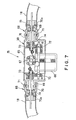
- a stroller 10 in a third embodiment according to the present invention will be described.
- a housing 65 included in a folding part operating mechanism 25 is mounted on a horizontal middle part 30.
- a pulley 67 is supported for turning in the housing 65.
- the pulley 67 is turned by an operating lever 66.
- the operating lever 66 is operated to turn the pulley 67, locking members 20 included in the stroller 10 is disengaged from the associated parts.
- Each of the joints 68 has a first joint member 69 attached to one end of the housing 65 and having a projection, and a second joint member 70 connected to the side pipe 18 and having two corresponding projections.
- the projection of the first joint member 69 is fitted in the space between the two corresponding projections of the second joint member 70 and is pivotally joined to the two corresponding projections of the second joint member 70 for turning about an axis 71 perpendicular to the axis of a horizontal middle part 30 of the handle 15.
- Two drive gears 72 are disposed in the housing 65 so as to be turned by the operating lever 66, and driven gears 73 are engaged with the drive gears 72, respectively.
- a shape memory spring 74 has one end fixed to a central part of each driven gear 73 and the other end fixedly fitted in a bore formed in the second joint member 70.
- the operating lever 66 When the operating lever 66 is operated to turn the drive gears 72 with the handle 15 to be set in an unfolded state as shown in Fig. 7, the driven gears 73 are turned and the shape memory springs 74 are twisted. Consequently, the shape memory springs 74 bend in an original shape corresponding to a twist, i.e., a shape resembling a right-angled bend, such that the second joint members 70 are extended in a direction perpendicular to the axis of the horizontal middle part 30 as shown in a left part of Fig. 8. Thus the right and the left side pipes 18 are held in the folded state. When the shape memory springs 74 are untwisted, the shape memory springs 74 straighten to bring the handle 5 in the unfolded state.
- a twist i.e., a shape resembling a right-angled bend
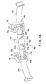
- a stroller 10 in a fourth embodiment according to the present invention will be described.
- a folding part operating mechanism 25a is combined with a rear connecting bar 22 (Fig. 19) connecting right and left rear legs 14 included in the stroller 10.
- the connecting bar 22 has a right end section 22b, a left end section 22b and a middle section 22a.
- the right and the left end section 22b are connected to the opposite ends of the middle section 22a by joints 75, respectively.
- a tubular member 76 is put on the middle section 22a.
- First bevel gears 77 are fixed to the opposite ends of the tubular member 76, respectively.
- a second bevel gear 79 is supported on a joint pin 78 included in each of the joints 75, is engaged with the first bevel gear 77, and is fixed to an outer joint member 75a included in the joint 75 and connected to the end section 22b.
- An operating lever holding member 80 projects obliquely upward toward the rear of the stroller 10 from the tubular member 76.
- a hollow operating lever 81 pivoted on the operating lever holding member 80 so as to be turnable in a predetermined angular range.
- a locking bolt 82 is supported slidably in the operating lever 81 and is pushed toward the middle section 22a by a spring, not shown.
- a guide pin 83 is attached laterally to the outer end of the bolt 82. The opposite ends of the guide pin 83 are engaged in V-shaped guide grooves 84 diverging in a direction away from the middle section 22a, i.e., toward the tip of the lever 81, and formed on the opposite inner surfaces of the operating lever 81, respectively.
- the middle section 22a is provided with holes 85a and 85b.
- the inner end of the bolt 82 can be engaged in the hole 85a when the rear connecting bar 22 is unfolded, and can be engaged in the hole 85b when the rear connecting bar 22 is folded.
- the joints 75 are covered with covers c indicated by chain lines in Fig. 9.
- the tubular member 76 fixedly provided with the first bevel gears 77, and the second bevel gears 79 constitute the folding part operating mechanism 25a.
- the inner end of the bolt 82 is engaged in the hole 85a of the middle section 22a as shown in Fig. 9 when the rear connecting bar 22 is unfolded to hold the rear connecting bar 22 in the unfolded state.
- the operating lever 81 is operated, for example, by foot to turn the same on the operating lever holding member 80.
- the guide pin 83 is moved along the guide grooves 84 to pull the bolt 82 out of the hole 85a.
- the operating lever 81 is depressed, for example, by foot to turn the tubular member 76 on the middle section 22a.
- the first bevel gears 77 turns the second bevel gears 79 on the joint pins 78, whereby the end sections 22b are turned forward and are set in the folded state.
- the operating lever 81 is turned in the opposite direction to unfold the end sections 22b through the first bevel gears 77 and the second bevel gears 79.
- Fig. 10 shows a modification of the folding part operating mechanism 25a shown in Fig. 9.
- a coil spring 86 is wound around a second bevel gear 79.
- the coil spring 86 has one end connected to the second bevel gear 79 and the other end connected to an outer joint member 75a.
- a stroller 10 in a fifth embodiment according to the present invention will be described with reference to Fig. 11.
- a rear connecting bar 22 has a middle section 22a, and end sections 22b connected to the opposite ends of the middle section 22a by joints 75, respectively.
- the end sections 22b can be turned on the joints 75 to fold the rear connecting bar 22.
- a tubular member 76 is mounted on the middle section 22a, and first bevel gears 77 are connected fixedly to the opposite ends of the middle section 22a, respectively.
- Second bevel gears 79 are supported on joint pins 78 and are engaged with the first bevel gears 77, respectively.
- Plates 87 are attached fixedly to the second bevel gears 79. End parts of the plates 87 are connected to the end sections 22b by connecting rods 88, respectively.
- a spring 89 is extended between parts, spaced from the joint pins 78 of the plates 87. Therefore, the plates 87 and the end sections 22b are urged forward by the springs 89.
- An operating lever 90 is fastened to the tubular member 76.
- the operating lever 90 is raised in the direction of the arrow to turn the end sections 22b forward through the first bevel gears 77, the second bevel gears 79 and the plates 87 to positions indicated by two-dot chain lines in Fig. 12, respectively. Since the end sections 22b are urged forward by the spring 89, the end sections 22b can be turned forward by applying a low force to the operating lever 90 and the rear connecting bar 22 can be relatively easily folded.
- the operating lever 90 is depressed to turn the end sections 22b rearward through the first bevel gears 77, the second bevel gears 79 and the plates 87 to set the connecting bar in the unfolded state.
- end sections 22b of the rear connecting bar 22 of the fifth embodiment are urged in the folding direction by the spring 89
- end sections 21b of a front connecting bar 21, similarly to the end sections 22b of the rear connecting bar 22, may be urged in the folding direction by extending a spring 91 between the end sections 21b to facilitate folding the stroller 10.
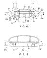
- a stroller 10 in a sixth embodiment according to the present invention will be described with reference to Figs. 14 and 15.
- a folding rear connecting bar 22 connecting right and left rear legs 14 has a middle section 22a, and end sections 22b connected to the opposite ends of the middle section 22a by joints 75, respectively.
- a pulley 93 having two disks 93a, i.e., right and left disks 93a, connected to a base part of an operating lever 92 and mounted for turning on the middle section 22a of the rear connecting bar 22.
- Two wires 94 are wound in the same direction around the pulley 93, and the free ends of the wires 94 are fixed to the pulley 93.
- a guide member 95 projects forward from the middle section 22a through a space between the two disks 93a. The guide member 95 guides the wires 94 having the ends fixed to the pulley 93 so as to cross each other.
- the other ends of the wires 94 are connected to middle parts of the end sections 22b, respectively.
- the operating lever 92 connected to the pulley 93 is hollow.
- Abolt 97 is extended axially slidably in the operating lever 92 and is pushed toward the middle section 22a by a spring 96.
- a plate 99 provided with a knob 98 is pivoted on an outer free end part of the operating lever 92.
- the plate 99 is connected to the outer end of the bolt 97 by a link 100.
- the middle section 22a is provided with a hole 85a in which the front end of the bolt 97 is engaged when the rear connecting bar 22 is unfolded and a hole 85b in which the front end of the bolt 97 is engaged when the rear connecting bar 22 is folded.
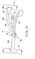
- a stroller 10 in a seventh embodiment according to the present invention will be described with reference to Fig. 16.
- a folding rear connecting bar 22 has a middle section 22a, and end sections 22b connected to the opposite ends of the middle section 22a by joints 75, respectively.
- a tubular member 102 provided with an operating lever 101 is mounted for turning on the middle section 22a.
- Two inclined slots 103 diverging from each other are formed in a front part of the tubular member 102.
- Projections 105 projecting from inner end parts of connecting rods 104 capable of axially sliding on the middle section 22a toward and away from each other are engaged in the inclined slots 103, respectively.
- Outer ends of the connecting rods 104 are connected to rods 106 connected to parts of outer joint members 75a of the joints 75 at a distance from turning axes of the outer joint members 75a, respectively.
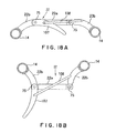
- a stroller 10 in an eighth embodiment according to the present invention will be described with reference to Fig. 17.
- a folding rear connecting bar 22 has a middle section 22a, and end sections 22b connected to the opposite ends of the middle section 22a by joints 75, respectively.
- An operating rod 107 is formed integrally with one of the end sections 22b so as to extend from the inner end of the same end section 22b.
- a middle part of the operating rod 107 and a middle part of the other end section 22b are connected by a link 108.
- Fig. 18A is a plan view of the rear connecting bar 22 in an unfolded state.
- the operating rod 107 is pulled rearward. Consequently, the end section 22b united with the operating rod 107 turns together with the operating rod 107 on a joint pin, and the other end section 22b is turned forward relative to the middle section 22a by the link 108, and the rear connecting bar 22 is folded as shown in Fig. 18B.
- the folded rear connecting bar 22 can be unfolded as shown in Fig. 18A, by pushing the operating lever 107 forward.
- the stroller foldable in three of the present invention can be folded by a remote operation, and the user is able to fold the stroller with continuously grabbing the horizontal middle part of the stroller by a comparatively simple, continuous operation.
Landscapes
- Engineering & Computer Science (AREA)
- Chemical & Material Sciences (AREA)
- Combustion & Propulsion (AREA)
- Transportation (AREA)
- Mechanical Engineering (AREA)
- Health & Medical Sciences (AREA)
- Public Health (AREA)
- Carriages For Children, Sleds, And Other Hand-Operated Vehicles (AREA)
- Chairs For Special Purposes, Such As Reclining Chairs (AREA)
Applications Claiming Priority (2)
| Application Number | Priority Date | Filing Date | Title |
|---|---|---|---|
| JP2001242354A JP4937473B2 (ja) | 2001-08-09 | 2001-08-09 | ベビーカーの折り畳み操作装置 |
| JP2001242354 | 2001-08-09 |
Publications (2)
| Publication Number | Publication Date |
|---|---|
| EP1283145A2 true EP1283145A2 (fr) | 2003-02-12 |
| EP1283145A3 EP1283145A3 (fr) | 2005-10-12 |
Family
ID=19072637
Family Applications (1)
| Application Number | Title | Priority Date | Filing Date |
|---|---|---|---|
| EP02017952A Withdrawn EP1283145A3 (fr) | 2001-08-09 | 2002-08-09 | Poussette pliable en trois |
Country Status (7)
| Country | Link |
|---|---|
| US (2) | US6860504B2 (fr) |
| EP (1) | EP1283145A3 (fr) |
| JP (1) | JP4937473B2 (fr) |
| KR (1) | KR101527427B1 (fr) |
| CN (1) | CN100366486C (fr) |
| SG (1) | SG143015A1 (fr) |
| TW (1) | TW588008B (fr) |
Cited By (2)
| Publication number | Priority date | Publication date | Assignee | Title |
|---|---|---|---|---|
| WO2024153735A1 (fr) * | 2023-01-18 | 2024-07-25 | Wonderland Switzerland Ag | Poussette |
| TWI914704B (zh) | 2023-01-18 | 2026-02-11 | 瑞士商明門瑞士股份有限公司 | 兒童推車 |
Families Citing this family (39)
| Publication number | Priority date | Publication date | Assignee | Title |
|---|---|---|---|---|
| JP4416881B2 (ja) * | 1999-10-12 | 2010-02-17 | コンビ株式会社 | ベビーカーの折畳み操作装置 |
| JP2003054418A (ja) * | 2001-08-17 | 2003-02-26 | Combi Corp | 遠隔操作装置およびこれを備えたベビーカー |
| US6921102B2 (en) * | 2001-10-18 | 2005-07-26 | Ben Ming Hsia | One-hand operational control device of foldable stroller |
| JP3967271B2 (ja) * | 2003-02-04 | 2007-08-29 | アップリカ育児研究会アップリカ▲葛▼西株式会社 | 折畳式乳母車 |
| CN1329235C (zh) * | 2003-04-03 | 2007-08-01 | 好孩子儿童用品有限公司 | 婴儿推车牵引索驱动机构的二次保险装置 |
| US7021650B2 (en) * | 2003-08-07 | 2006-04-04 | Wonderland Nurserygoods Co., Ltd. | Collapsing device for carrier |
| US9173802B2 (en) | 2003-10-07 | 2015-11-03 | Amg Medical, Usa. | Mobile support assembly |
| TWM256123U (en) * | 2004-02-18 | 2005-02-01 | Link Treasure Ltd | Baby umbrella stroller capable of being folded with one hand |
| ITVR20050107A1 (it) * | 2005-09-14 | 2007-03-15 | L Inglesina Baby Spa | Dispositivo di impugnatura, particolarmente per passeggini, carrozzine e simili |
| NL1030330C2 (nl) * | 2005-11-01 | 2007-05-03 | Royalty Bugaboo Gmbh | Opvouwbare wagen, zoals een buggy, met fixerend dwarsstangsysteem. |
| US7451992B2 (en) | 2006-01-31 | 2008-11-18 | Phillip Minyard Willis | Mobile support assembly |
| US7717457B2 (en) * | 2006-05-15 | 2010-05-18 | Wonderland Nurserygoods Co., Ltd. | Stroller with spring-assisted fold mechanism |
| TWM325960U (en) * | 2006-09-29 | 2008-01-21 | Golden Point Marketing Ltd | Folding control mechanism for baby stroller |
| US7731220B2 (en) * | 2006-12-19 | 2010-06-08 | Wonderland Nurserygoods Co., Ltd. | Frame assembly for double-seat baby stroller |
| CN201082718Y (zh) * | 2007-07-19 | 2008-07-09 | 明门实业股份有限公司 | 婴儿车的单手收合致动机构 |
| US20090102149A1 (en) * | 2007-10-22 | 2009-04-23 | Graco Children's Products Inc. | Foldable pushcart and foldable baby carriage |
| US8439376B2 (en) * | 2008-07-08 | 2013-05-14 | Amg Medical, Usa. | Mobile support assembly |
| JP5234802B2 (ja) * | 2009-04-22 | 2013-07-10 | 株式会社リッチェル | 折畳み式ベビーカーのロック解除装置、該ロック解除装置を備えた折畳み式ベビーカー |
| CN102211604B (zh) * | 2010-04-09 | 2014-03-05 | 明门香港股份有限公司 | 可收合式的婴儿承载装置 |
| NL2005363C2 (nl) * | 2010-09-16 | 2012-03-19 | Mutsy Bv | Inrichtingen voor het ondersteunen van een kind. |
| JP5963394B2 (ja) * | 2011-03-03 | 2016-08-03 | アップリカ・チルドレンズプロダクツ合同会社 | 折畳式乳母車 |
| US8517412B2 (en) | 2011-09-22 | 2013-08-27 | Baby Trend Inc. | Foldable stroller frame having three sections joined to and foldable around a common hub structure |
| US20130113185A1 (en) * | 2011-11-07 | 2013-05-09 | Dynamic Brands, Llc | Baby stroller |
| US9199658B2 (en) * | 2012-06-22 | 2015-12-01 | Khai Gan Chuah | Baby stroller folding mechanism |
| CN103661544B (zh) * | 2012-08-30 | 2016-03-02 | 明门香港股份有限公司 | 关节装置 |
| JP5548747B2 (ja) * | 2012-09-25 | 2014-07-16 | 株式会社島製作所 | スライド部材のロック装置およびこのロック装置を備えた手押し車 |
| US9463822B2 (en) | 2014-01-10 | 2016-10-11 | Dorel Juvenile Group, Inc. | Stroller |
| CN203766857U (zh) | 2014-03-27 | 2014-08-13 | 克斯克管理公司 | 推车 |
| US9315205B2 (en) * | 2014-09-18 | 2016-04-19 | Khai Gan Chuah | Folding mechanism of baby stroller |
| CN104986207B (zh) * | 2015-07-09 | 2018-01-30 | 廖整辉 | 折叠童车 |
| US9308929B1 (en) | 2015-08-17 | 2016-04-12 | Dorel Juvenile Group, Inc. | Stroller |
| GB2547515B (en) * | 2015-12-19 | 2019-09-04 | Wonderland Switzerland Ag | Infant stroller apparatus |
| CN106004965B (zh) * | 2016-06-08 | 2019-05-10 | 中山盛加儿童用品有限公司 | 一种折叠手推车 |
| EP3747731B1 (fr) * | 2018-07-16 | 2023-01-18 | Shanghai Dorel Juvenile Co., Ltd. | Mécanisme de pliage de poignée, poignée à trois plis employant le mécanisme de pliage, et chariot les comportant |
| CN119858593A (zh) * | 2020-11-13 | 2025-04-22 | 明门瑞士股份有限公司 | 婴儿车 |
| CN112462098B (zh) * | 2020-11-30 | 2022-07-29 | 广东电网有限责任公司韶关供电局 | 一种折叠式操作杆 |
| KR102411848B1 (ko) * | 2020-12-08 | 2022-06-22 | 주식회사 이노디자인 | 접이식 핸들 |
| JP7585816B2 (ja) | 2021-01-27 | 2024-11-19 | マツダ株式会社 | 車椅子 |
| JP7578005B2 (ja) * | 2021-01-27 | 2024-11-06 | マツダ株式会社 | 車椅子 |
Family Cites Families (32)
| Publication number | Priority date | Publication date | Assignee | Title |
|---|---|---|---|---|
| US2437778A (en) * | 1944-02-02 | 1948-03-16 | Walkabout Company | Portable support for invalids |
| US4191397A (en) * | 1977-06-15 | 1980-03-04 | Kassai Kabushikikaisha | Baby carriage |
| JPS5858972U (ja) * | 1981-10-16 | 1983-04-21 | アップリカ葛西株式会社 | 乳母車の後脚 |
| JPS58202157A (ja) * | 1982-05-19 | 1983-11-25 | アップリカ葛西株式会社 | 乳母車の押棒と押棒連結棒との連結部構造 |
| JPS59106366A (ja) * | 1982-12-11 | 1984-06-20 | 象印ベビ−株式会社 | ベビ−カ |
| JPS59149563U (ja) * | 1983-03-28 | 1984-10-05 | アップリカ葛西株式会社 | 乳母車の押棒と押棒連結棒との連結部構造 |
| JPS59157964U (ja) * | 1983-04-08 | 1984-10-23 | アップリカ葛西株式会社 | 乳母車の押棒と押棒連結棒との連結部構造 |
| JPS60146753A (ja) * | 1984-01-11 | 1985-08-02 | アップリカ葛西株式会社 | 乳母車の握り棒のロツク機構 |
| JPS60199763A (ja) * | 1984-03-23 | 1985-10-09 | アップリカ葛西株式会社 | 乳母車の握り棒のロツク機構 |
| US4765645A (en) * | 1987-01-30 | 1988-08-23 | Louis Shamie | Safety spreader bar lock for umbrella stroller |
| JPH0638777Y2 (ja) * | 1988-05-17 | 1994-10-12 | アップリカ葛西株式会社 | 乳母車の握り棒のロック機構 |
| US5205579A (en) * | 1990-10-08 | 1993-04-27 | Combi Corporation | Handle bar for baby carriage |
| JP3040496B2 (ja) * | 1991-01-11 | 2000-05-15 | アップリカ▲葛▼西株式会社 | 折りたたみ式乳母車およびそこに用いられる折りたたみ機構 |
| KR960003727Y1 (ko) * | 1994-02-05 | 1996-05-06 | 주식회사 한국아프리카 | 유모차 |
| US5535483A (en) * | 1994-02-11 | 1996-07-16 | Jane, S.A. | Locking and unlocking device for the folding of baby carriages |
| JP3311163B2 (ja) * | 1994-09-21 | 2002-08-05 | アップリカ▲葛▼西株式会社 | 乳母車およびその座席のための座板の製造方法 |
| JP3385113B2 (ja) * | 1994-10-20 | 2003-03-10 | アップリカ▲葛▼西株式会社 | 乳母車の握り棒 |
| JP3764515B2 (ja) * | 1994-11-25 | 2006-04-12 | コンビ株式会社 | 折りたたみ式の着座装置 |
| TW280801B (fr) * | 1994-12-26 | 1996-07-11 | Aprica Kassai Kk | |
| DE29509125U1 (de) * | 1995-06-02 | 1995-08-17 | Rudi Schaller Metalltechnik GmbH, 96268 Mitwitz | Gestell für einen zusammenklappbaren Kinder- oder Puppen-Sitz- oder Liegewagen |
| US5664798A (en) * | 1995-07-11 | 1997-09-09 | Lu Kuang Incorporation | Automatic folding frame for baby carriage |
| GB2318099B (en) * | 1996-10-10 | 2000-11-29 | Huang Li Chu Chen | Foldable mechanism for use in a stroller |
| US6068284A (en) * | 1997-07-29 | 2000-05-30 | Graco Children's Products Inc. | Stroller with one hand release mechanism and one hand release mechanism thereof |
| JP2000108904A (ja) * | 1998-10-06 | 2000-04-18 | Combi Corp | ベビーカー折畳み機構の開閉操作機構 |
| NL1012334C2 (nl) * | 1999-06-15 | 2000-12-18 | Maxi Miliaan Bv | Wandelwagen. |
| KR200164019Y1 (ko) * | 1999-07-07 | 2000-02-15 | 주식회사햇님토이 | 유모차 |
| JP4416881B2 (ja) * | 1999-10-12 | 2010-02-17 | コンビ株式会社 | ベビーカーの折畳み操作装置 |
| DE20001963U1 (de) * | 2000-02-04 | 2000-05-04 | Cheng, Kenny, Taipeh/T'ai-pei | Zusammenklappvorrichtung mit Einhandbetätigung |
| US6339862B1 (en) * | 2000-02-09 | 2002-01-22 | Kenny Cheng | Single-handed folding device (II) |
| CN2440403Y (zh) * | 2000-07-26 | 2001-08-01 | 中山市隆成日用制品有限公司 | 婴儿车可单手收合结构 |
| JP4689018B2 (ja) * | 2000-09-21 | 2011-05-25 | コンビ株式会社 | ツインタイプベビーカー |
| JP2003054418A (ja) * | 2001-08-17 | 2003-02-26 | Combi Corp | 遠隔操作装置およびこれを備えたベビーカー |
-
2001
- 2001-08-09 JP JP2001242354A patent/JP4937473B2/ja not_active Expired - Fee Related
-
2002
- 2002-08-08 KR KR1020020046784A patent/KR101527427B1/ko not_active Expired - Fee Related
- 2002-08-08 SG SG200204791-8A patent/SG143015A1/en unknown
- 2002-08-08 US US10/214,488 patent/US6860504B2/en not_active Expired - Fee Related
- 2002-08-08 TW TW091117919A patent/TW588008B/zh not_active IP Right Cessation
- 2002-08-09 CN CNB021286531A patent/CN100366486C/zh not_active Expired - Fee Related
- 2002-08-09 EP EP02017952A patent/EP1283145A3/fr not_active Withdrawn
-
2005
- 2005-01-18 US US11/035,957 patent/US7168728B2/en not_active Expired - Fee Related
Non-Patent Citations (1)
| Title |
|---|
| None |
Cited By (2)
| Publication number | Priority date | Publication date | Assignee | Title |
|---|---|---|---|---|
| WO2024153735A1 (fr) * | 2023-01-18 | 2024-07-25 | Wonderland Switzerland Ag | Poussette |
| TWI914704B (zh) | 2023-01-18 | 2026-02-11 | 瑞士商明門瑞士股份有限公司 | 兒童推車 |
Also Published As
| Publication number | Publication date |
|---|---|
| JP4937473B2 (ja) | 2012-05-23 |
| KR101527427B1 (ko) | 2015-06-08 |
| US6860504B2 (en) | 2005-03-01 |
| KR20030014649A (ko) | 2003-02-19 |
| TW588008B (en) | 2004-05-21 |
| CN100366486C (zh) | 2008-02-06 |
| EP1283145A3 (fr) | 2005-10-12 |
| US7168728B2 (en) | 2007-01-30 |
| US20030030250A1 (en) | 2003-02-13 |
| SG143015A1 (en) | 2008-06-27 |
| HK1054532A1 (zh) | 2003-12-05 |
| US20050121882A1 (en) | 2005-06-09 |
| JP2003054413A (ja) | 2003-02-26 |
| CN1405046A (zh) | 2003-03-26 |
Similar Documents
| Publication | Publication Date | Title |
|---|---|---|
| US6860504B2 (en) | Stroller foldable in three | |
| US7246813B2 (en) | Baby carriage folding mechanism for a folding baby carriage | |
| EP2240359B1 (fr) | Châssis de poussette pliable d'une main | |
| EP3299251B1 (fr) | Appareil de poussette pour enfants | |
| US6443479B2 (en) | Locking device with safety arrangement for collapsable stroller | |
| EP0494736B1 (fr) | Voiture d'enfant pliable et mécanisme de pliage utilisé là-dedans | |
| EP2368784A1 (fr) | Poussette pour enfants pliable | |
| TWM550247U (zh) | 易於展開定位之手推車 | |
| US6267405B1 (en) | Foldable stroller | |
| CN111361624A (zh) | 联动解锁的儿童推车 | |
| CN211844589U (zh) | 童车骨架以及儿童推车 | |
| CN112224268B (zh) | 车架收折机构及婴儿推车 | |
| JP2012116369A (ja) | 子供用運搬車 | |
| JP3949276B2 (ja) | 手押し車の押棒に用いられる連結杆 | |
| JP3027803B2 (ja) | 折りたたみ式乳母車 | |
| JP2846299B2 (ja) | 折りたたみ式乳母車 | |
| JP2846164B2 (ja) | 折りたたみ式乳母車およびそこに用いられる折りたたみ機構 | |
| CN114194276A (zh) | 童车车架和童车 | |
| HK1054532B (en) | Baby carrier foldable in three | |
| AU5414501A (en) | Baby carriage |
Legal Events
| Date | Code | Title | Description |
|---|---|---|---|
| PUAI | Public reference made under article 153(3) epc to a published international application that has entered the european phase |
Free format text: ORIGINAL CODE: 0009012 |
|
| AK | Designated contracting states |
Designated state(s): AT BE BG CH CY CZ DE DK EE ES FI FR GB GR IE IT LI LU MC NL PT SE SK TR |
|
| AX | Request for extension of the european patent |
Extension state: AL LT LV MK RO SI |
|
| PUAL | Search report despatched |
Free format text: ORIGINAL CODE: 0009013 |
|
| AK | Designated contracting states |
Kind code of ref document: A3 Designated state(s): AT BE BG CH CY CZ DE DK EE ES FI FR GB GR IE IT LI LU MC NL PT SE SK TR |
|
| AX | Request for extension of the european patent |
Extension state: AL LT LV MK RO SI |
|
| RIC1 | Information provided on ipc code assigned before grant |
Ipc: 7B 62B 9/20 B Ipc: 7B 62B 7/06 A |
|
| 17P | Request for examination filed |
Effective date: 20060331 |
|
| AKX | Designation fees paid |
Designated state(s): ES FR GB IT |
|
| 17Q | First examination report despatched |
Effective date: 20060810 |
|
| GRAP | Despatch of communication of intention to grant a patent |
Free format text: ORIGINAL CODE: EPIDOSNIGR1 |
|
| STAA | Information on the status of an ep patent application or granted ep patent |
Free format text: STATUS: THE APPLICATION IS DEEMED TO BE WITHDRAWN |
|
| 18D | Application deemed to be withdrawn |
Effective date: 20080920 |