EP1283321B1 - Drehkipp-Beschlag - Google Patents
Drehkipp-Beschlag Download PDFInfo
- Publication number
- EP1283321B1 EP1283321B1 EP02011574A EP02011574A EP1283321B1 EP 1283321 B1 EP1283321 B1 EP 1283321B1 EP 02011574 A EP02011574 A EP 02011574A EP 02011574 A EP02011574 A EP 02011574A EP 1283321 B1 EP1283321 B1 EP 1283321B1
- Authority
- EP
- European Patent Office
- Prior art keywords
- tilt
- accordance
- bearing
- turn fitting
- window
- Prior art date
- Legal status (The legal status is an assumption and is not a legal conclusion. Google has not performed a legal analysis and makes no representation as to the accuracy of the status listed.)
- Expired - Lifetime
Links
Images

Classifications
-
- E—FIXED CONSTRUCTIONS
- E05—LOCKS; KEYS; WINDOW OR DOOR FITTINGS; SAFES
- E05D—HINGES OR SUSPENSION DEVICES FOR DOORS, WINDOWS OR WINGS
- E05D5/00—Construction of single parts, e.g. the parts for attachment
- E05D5/02—Parts for attachment, e.g. flaps
- E05D5/0215—Parts for attachment, e.g. flaps for attachment to profile members or the like
- E05D5/0223—Parts for attachment, e.g. flaps for attachment to profile members or the like with parts, e.g. screws, extending through the profile wall or engaging profile grooves
- E05D5/0238—Parts for attachment, e.g. flaps for attachment to profile members or the like with parts, e.g. screws, extending through the profile wall or engaging profile grooves with parts engaging profile grooves
-
- E—FIXED CONSTRUCTIONS
- E05—LOCKS; KEYS; WINDOW OR DOOR FITTINGS; SAFES
- E05D—HINGES OR SUSPENSION DEVICES FOR DOORS, WINDOWS OR WINGS
- E05D15/00—Suspension arrangements for wings
- E05D15/48—Suspension arrangements for wings allowing alternative movements
- E05D15/52—Suspension arrangements for wings allowing alternative movements for opening about a vertical as well as a horizontal axis
- E05D15/5214—Corner supports
-
- E—FIXED CONSTRUCTIONS
- E05—LOCKS; KEYS; WINDOW OR DOOR FITTINGS; SAFES
- E05D—HINGES OR SUSPENSION DEVICES FOR DOORS, WINDOWS OR WINGS
- E05D7/00—Hinges or pivots of special construction
- E05D7/02—Hinges or pivots of special construction for use on the right-hand as well as the left-hand side; Convertible right-hand or left-hand hinges
-
- E—FIXED CONSTRUCTIONS
- E05—LOCKS; KEYS; WINDOW OR DOOR FITTINGS; SAFES
- E05Y—INDEXING SCHEME ASSOCIATED WITH SUBCLASSES E05D AND E05F, RELATING TO CONSTRUCTION ELEMENTS, ELECTRIC CONTROL, POWER SUPPLY, POWER SIGNAL OR TRANSMISSION, USER INTERFACES, MOUNTING OR COUPLING, DETAILS, ACCESSORIES, AUXILIARY OPERATIONS NOT OTHERWISE PROVIDED FOR, APPLICATION THEREOF
- E05Y2900/00—Application of doors, windows, wings or fittings thereof
- E05Y2900/10—Application of doors, windows, wings or fittings thereof for buildings or parts thereof
- E05Y2900/13—Type of wing
- E05Y2900/132—Doors
-
- E—FIXED CONSTRUCTIONS
- E05—LOCKS; KEYS; WINDOW OR DOOR FITTINGS; SAFES
- E05Y—INDEXING SCHEME ASSOCIATED WITH SUBCLASSES E05D AND E05F, RELATING TO CONSTRUCTION ELEMENTS, ELECTRIC CONTROL, POWER SUPPLY, POWER SIGNAL OR TRANSMISSION, USER INTERFACES, MOUNTING OR COUPLING, DETAILS, ACCESSORIES, AUXILIARY OPERATIONS NOT OTHERWISE PROVIDED FOR, APPLICATION THEREOF
- E05Y2900/00—Application of doors, windows, wings or fittings thereof
- E05Y2900/10—Application of doors, windows, wings or fittings thereof for buildings or parts thereof
- E05Y2900/13—Type of wing
- E05Y2900/148—Windows
Definitions
- the invention relates to a turn-tilt fitting for a window, door or the like of metal, e.g. Aluminum, having the features of the preamble of claim 1.
- metal e.g. Aluminum
- a turn-tilt fitting is eg from the EP-A-0 478 519 which has the features of the preamble of claim 1.
- the corner bearing housing of this turn-tilt fitting is clamped by means of a screw and a clamping element in the groove of a profile frame.
- the corner bearing housing itself has a receiving opening for the tab of the bearing strip, wherein the bearing strip must have been inserted into the corner bearing housing before it is fastened by means of the screw to the frame.
- the tab is additionally penetrated by the fastening screw.
- the invention is therefore based on the object to provide a tilt-and-turn fitting, which is suitable for metal frame and which can be used for both left and right hinged windows, doors or the like.
- the pivot bearing should be as close to the frame, so that even large forces can be supported.
- the corner bearing housing and the bearing strip Due to the inventive design of the corner bearing housing and the bearing strip as a mirror-symmetrical components, they can be used for left-battered as well as right hinged windows, doors or the like, which the Storage considerably simplified.
- the corner bearing housing is designed in the form of a housing block, in which the pivot bearing is provided for the tab or for the bearing strip. Due to the immediate vicinity of the pivot bearing to the frame very high forces can be absorbed or intercepted without damage to the corner bearing housing or the pivot bearing are to be feared.
- the plane of symmetry runs horizontally when the fitting is installed.
- the plane of symmetry of the Ecklagergeophuses and the bearing strip is orthogonal to the pivot axis of the window, the door or the like.
- the Ecklagergeophuse and the bearing tape must therefore only be turned so that the previous upper side points down when used on a differently battered window. Due to the symmetrical structure, they can be used equally well for both sides of the window.
- the Ecklagergeophuse has in its receiving opening a bearing shell for the tab of the bearing strip.
- This bearing shell serves to compensate for any play occurring and the friction between the bearing strip and corner bearing housing reduce.
- the bearing shell serves to minimize the noise when tilting the wing and serves as a resistor for the heat and sound transmission from the corner bearing housing to the bearing band, ie from the frame to the wing.
- the bearing shell made of plastic and is provided with in the direction of the tab projecting ribs.
- air cushions are created, which further increase the effects mentioned above, wherein the ribs further reduce the friction of the bearing strip in the pivot bearing.
- the spaces between the ribs can also serve as pockets for lubricants.
- the bearing shell is mirror-symmetrical, wherein the mirror plane is orthogonal to the pivot axis of the window, the door or the like.
- another mirror plane is parallel to the pivot axis and orthogonal to the plane of the window, the door or the like.
- the bearing shell is clipped into the receiving opening of the Ecklagergeophuses and locked in their final position.
- the bearing shell on locking lugs, which engage either in detent openings or engage behind corresponding shoulders on Ecklagergeophuse.
- the bearing band consists of plastic. By appropriate dimensioning can be ensured that the forces are transmitted safely, the bearing pin or the bearing axis for pivoting the window made of metal.
- corner bearing housing and the bearing strip made of metal, in particular die-cast.
- metal in particular die-cast.
- aluminum or another light metal alloy is suitable.
- the tab In order to transmit high forces, the tab is formed breakthrough-free. This means that after the insertion of the tab in the. Auf Spotifybohrung of the pivot bearing of the corner bearing housing, the fasteners for the corner bearing housing can not be operated. Thus, manipulations are no longer possible.
- an advantageous embodiment of the invention provides the corner bearing housing has at least one sliding block for fixing the corner bearing housing to the frame.
- the sliding block can also be provided an eccentric. Both the sliding block and the eccentric are actuated by the corner bearing housing, in particular via openings, such as holes or the like.
- a hexagon wrench with which the sliding block or the eccentric is rotated or pivoted.
- the sliding block or eccentric may be designed to be jammed in the groove of the frame or moved in the direction of a Nutensteges so that it jammed the Nutensteg between them and the Ecklagergephinuse.
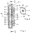
- the Fig. 1 shows a generally designated 10 Ecklagergeophuse, projecting from which two nuts 12 for attachment of the Ecklagergeophuses 10 in a (not shown) groove of a profile frame.
- screws 14 are screwed, which are provided for example with a hexagon socket.
- a centering projection 64 Between these two sliding blocks 12 is a centering projection 64, which facilitates the insertion of the corner bearing housing 10 in the profile groove and holds this until it over the Nutensteine is fixed.
- the sliding blocks 12 have a different shape from the circular shape, so that they can be pushed inserted between the groove strips in the groove. If they are in the groove, then they are rotated by 90 ° and engage behind the groove strips. By the stepped edge 60, they center the corner bearing housing 10 with respect to the groove. The corner 62 prevents over-rotation of the sliding block 12 in the groove and thus defines its locking end position.
- the screws 14 are actuated by a suitable tool through the corner bearing housing 10 therethrough.
- the corner bearing housing 10 on its housing wall 16 openings 18 (see Fig. 3 ) in the form of holes through which the tool can be passed. If the screws 14 are screwed into the sliding blocks 12, then the sliding block 12 is moved in the direction of the housing wall 20, whereby the profile webs between Nutentein 12 and housing wall 20 clamped and thereby the corner bearing housing 10 is attached to the profile frame.
- the corner bearing housing 10 also has a receiving opening 22 into which a bearing shell 24 is inserted.
- These Bearing shell 24 abuts the inner sides of the housing walls 16 and 18 and is supported on these.
- Clearly visible between the inner sides of the housing walls 16 and 20 and the bearing shell 24 are cylindrical-section-shaped cavities 26, which give the bearing shell 24 a certain elasticity in this area.
- the sliding surfaces for a pivotally mounted tab 34 form a bearing strip 36. Since the bearing shell 24 is made of plastic, thereby the friction between the bearing shell 24 and the bearing band 36 is considerably reduced.
- the Fig. 2 shows a section through the bearing shell 24, from which clearly the ribs 32 can be seen.
- openings 38 can still be seen, through which the tool for actuating the screws 14 is guided.
- still elastically running retaining clips 40 can be seen, which have latching lugs 42 at their free end. These locking lugs 42 engage behind a shoulder 44 on the corner bearing housing 10, so that after insertion of the bearing shell 24 in the receiving opening 22 this is fixed captive.
- the retaining clips 40 nestle against bearing surfaces 46 or cover them these.
- the bearing surfaces 46 serve as a support for the bearing strip 36 and for its tab 34 and support the attached to the bearing band 36 window (not shown) from.
- the tab 34 has two part-circular portions 48, the radius of which corresponds in each case to the outer radius of the retaining clip 40.
- the tab 34 is pivoted on this section 48 on the retaining clip 40 and the bearing surface 46. In each case, only the lower portion 48 sits on the lower retaining clip 40 and the lower bearing surface 46.
- the tab 34 each have a retaining lug 50.
- the upper retaining lug 50 touches the adjacent retaining clip 40 of the bearing shell 24 slightly.
- the bearing band 36 is thus inserted into the receiving opening 22 of the corner bearing housing 10 in that first one of the sections 48 is placed on its associated retaining clip 40 of the bearing shell 24 and then the tab 34 is fully pivoted into the bearing shell 24.
- the opposite retaining lug 50 passes the retaining clip 40 assigned to it and also enters the bearing shell 24.
- the two lugs 50 prevent removal of the bearing band 36 when attempting to do so without Only pivot out of the bearing shell 24 to pull.
- the bearing strip 36 has an angular configuration and has a leg 52 which protrudes at right angles to the tab 34, to which side a bearing part of the pivot bearing, e.g. a bearing bush 54 for receiving a pivot pin forming the pivot pin 56 is integrally formed.
- the bearing strip 36 may be made of plastic, but the bearing pin 56 is made of metal for strength reasons.
- corner bearing housing 10 is constructed mirror-symmetrically to a horizontal plane of symmetry 58.
- the bearing shell 24 is as out FIG. 2 can be seen, in addition to a plane parallel to the plane of symmetry mirror symmetry.
- the tilting plane corresponding to the plane of sections II-II and III-III corresponds, is in the immediate vicinity of the sliding blocks 12 and thus to the profile frame, so that the leverage and moments can be kept small.
- the tab 34 is free from breakthroughs, so that the flow of force remains undisturbed within this tab 34.
- the screw heads the screws 14 covered with bearing tape 36 of the tab 34.
Landscapes
- Engineering & Computer Science (AREA)
- Mechanical Engineering (AREA)
- Hinges (AREA)
- Mirrors, Picture Frames, Photograph Stands, And Related Fastening Devices (AREA)
- Rear-View Mirror Devices That Are Mounted On The Exterior Of The Vehicle (AREA)
Description
- Die Erfindung betrifft einen Drehkipp-Beschlag für ein Fenster, eine Tür oder dergleichen aus Metall, z.B. Aluminium, mit den Merkmalen des Oberbegriffs des Anspruchs 1.
- Ein Drehkipp-Beschlag ist z.B. aus der
EP-A-0 478 519 bekannt welches die Merkmale des Oberbegriffs des Anspruchs 1 aufweist. Das Ecklagergehäuse dieses Drehkipp-Beschlages wird mittels einer Schraube und eines Spannelements in der Nut eines Profilrahmens festgeklemmt. Das Ecklagergehäuse selbst weist eine Aufnahmeöffnung für die Lasche des Lagerbandes auf, wobei das Lagerband in das Ecklagergehäuse eingeschoben worden sein muss, bevor dieses mittels der Schraube am Rahmen befestigt wird. Die Lasche wird zusätzlich von der Befestigungsschraube durchgriffen. Dies wird als nachteilig angesehen, da das Lagerband in das noch nicht fixierte Ecklagergehäuse eingefädelt werden muss und anschließend die Befestigungsschraube durch die Lasche hindurch in die Gewindebohrung des Spannelements eingefädelt werden muss. Ein weiterer Nachteil wird darin gesehen, dass für links angeschlagene und für rechts angeschlagene Fenster jeweils spezielle Ecklagergehäuse und noch zugehörige Lagerbänder benötigt werden. Dies bedingt eine aufwändige Lagerhaltung. - Außerdem ist aus der
DE-A-198 11 375 eine Winkelumlenkung für Metallrahmen bekannt, die jedoch ebenfalls speziell für den Linksanschlag bzw. für den Rechtsanschlag ausgebildet ist. - Auch aus der
EP-A-1 074 687 ist ein Beschlag für ein Drehkipp-Fenster bekannt. Dieser Beschlag ist zwar für rechts angeschlagene und für links angeschlagene Fenster gleichermaßen verwendbar, jedoch ist der Beschlag nicht geeignet, um an einem Metallrahmen befestigt werden zu können. Außerdem treten bei diesem Beschlag hohe Biegemomente auf, die eine stabile Ausgestaltung des Ecklagergehäuses bedingen. - Aus der
DE-U-87 00 849 ist ein Drehkipp-Beschlag mit einem Ecklagergehäuse mit Lagerband bekannt, welche in sich spiegelsymmetrisch ausgebildet sind. Dieser Beschlag ist für rechts und links angeschlagene Flügel geeignet, jedoch darf der Flügel nicht zu schwer sein. - Der Erfindung liegt daher die Aufgabe zugrunde, einen Drehkipp-Beschlag bereitzustellen, der für Metallrahmen geeignet ist und der sowohl für links als auch für rechts angeschlagene Fenster, Türen oder dergleichen verwendet werden kann. Außerdem soll sich das Schwenklager möglichst nahe am Rahmen befinden, so dass auch große Kräfte abgestützt werden können.
- Diese Aufgabe wird erfindungsgemäß bei einem Drehkipp-Beschlag gelöst, der die Merkmale des Anspruchs 1 aufweist.
- Durch die erfindungsgemäße Ausgestaltung des Ecklagergehäuses und des Lagerbandes als spiegelsymmetrische Bauteile können sie sowohl für links angeschlagene als auch für rechts angeschlagene Fenster, Türen oder dergleichen verwendet werden, was die Lagerhaltung wesentlich vereinfacht. Außerdem ist das Ecklagergehäuse in Form eines Gehäuseblockes ausgestaltet, in welchem das Schwenklager für die Lasche bzw. für das Lagerband vorgesehen ist. Durch die unmittelbare Nähe des Schwenklagers zum Rahmen können sehr hohe Kräfte aufgenommen bzw. abgefangen werden, ohne dass Beschädigungen des Ecklagergehäuses oder des Schwenklagers zu befürchten sind.
- Bei einer Weiterbildung ist vorgesehen, dass die Symmetrieebene bei eingebautem Beschlag horizontal verläuft. Die Symmetrieebene des Ecklagergehäuses und des Lagerbandes verläuft orthogonal zur Schwenkachse des Fensters, der Tür oder dergleichen. Das Ecklagergehäuse und das Lagerband müssen bei der Verwendung an einem anders angeschlagenen Fenster also lediglich so gedreht werden, dass die bisherige Oberseite nach unten zeigt. Aufgrund des symmetrischen Aufbaus können sie für beide Fensteranschlagseiten gleichermaßen gut verwendet werden.
- Gemäß einem bevorzugten Ausführungsbeispiel besitzt das Ecklagergehäuse in seiner Aufnahmeöffnung eine Lagerschale für die Lasche des Lagerbandes. Diese Lagerschale dient dazu, eventuell auftretendes Spiel auszugleichen und die Reibung zwischen Lagerband und Ecklagergehäuse zu verringern. Außerdem dient die Lagerschale zur Minimierung der Geräusche beim Kippen des Flügels und dient als Widerstand für die Wärme- und Schallübertragung vom Ecklagergehäuse zum Lagerband, d.h. vom Rahmen zum Flügel.
- Vorzugsweise besteht die Lagerschale aus Kunststoff und ist mit in Richtung auf die Lasche vorstehenden Rippen versehen. Auf diese Weise werden Luftpolster geschaffen, die die oben genannten Effekte noch erhöhen, wobei die Rippen die Reibung des Lagerbandes im Schwenklager noch weiter verringern. Die zwischen den Rippen entstehenden Freiräume können auch als Taschen für Schmiermittel dienen.
- Bevorzugterweise ist auch die Lagerschale spiegelsymmetrisch ausgebildet, wobei die Spiegelebene orthogonal zur Schwenkachse des Fensters, der Tür oder dergleichen verläuft. Außerdem verläuft eine weitere Spiegelebene parallel zur Schwenkachse und orthogonal zur Ebene des Fensters, der Tür oder dergleichen. Beim Einsetzen der Lagerschale muss also nicht auf deren Ausrichtung geachtet werden, was die Montage wesentlich erleichtert.
- Vorzugsweise ist die Lagerschale in die Aufnahmeöffnung des Ecklagergehäuses einklipsbar und verrastet in ihrer endgültigen Stellung. Hierfür weist die Lagerschale Rastnasen auf, die entweder in Rastöffnungen eingreifen oder entsprechende Schultern am Ecklagergehäuse hintergreifen.
- Mit Vorzug besteht das Lagerband aus Kunststoff. Durch entsprechende Dimensionierung kann sichergestellt werden, dass die auftretenden Kräfte sicher übertragen werden, wobei der Lagerbolzen bzw. die Lagerachse zum Schwenken des Fensters aus Metall besteht.
- Bei einem anderen Ausführungsbeispiel ist vorgesehen, dass das Ecklagergehäuse und das Lagerband aus Metall, insbesondere aus Druckguss, bestehen. Hierfür eignet sich insbesondere Aluminium oder eine andere Leichtmetalllegierung.
- Um hohe Kräfte übertragen zu können, ist die Lasche durchbruchfrei ausgebildet. Dies bedeutet, dass nach dem Einsetzen der Lasche in die.Aufnahmebohrung des Schwenklagers des Ecklagergehäuses die Befestigungselemente für das Ecklagergehäuse nicht mehr betätigt werden können. Somit sind auch Manipulationen nicht mehr möglich.
- Eine vorteilhafte Ausgestaltung der Erfindung sieht vor, dass das Ecklagergehäuse wenigstens einen Nutenstein zur Fixierung des Ecklagergehäuses am Rahmen aufweist. Anstelle des Nutensteins kann auch ein Exzenter vorgesehen sein. Sowohl der Nutenstein als auch der Exzenter werden durch das Ecklagergehäuse hindurch, insbesondere über Durchbrüche, wie Bohrungen oder dergleichen, betätigt. Hierfür dient z.B. ein Sechskantschlüssel, mit dem der Nutenstein oder der Exzenter gedreht bzw. verschwenkt wird. Der Nutenstein oder der Exzenter können so ausgebildet sein, dass er in der Nut des Rahmens verklemmt wird oder in Richtung eines Nutensteges bewegt wird, so dass er den Nutensteg zwischen sich und dem Ecklagergehäuse verklemmt.
- Weitere Vorteile, Merkmale und Einzelheiten der Erfindung ergeben sich aus der nachfolgenden Beschreibung, in der unter Bezugnahme auf die Zeichnung ein besonders bevorzugtes Ausführungsbeispiel beschrieben ist. Dabei können die in der Zeichnung dargestellten sowie in den Ansprüchen und in der Beschreibung erwähnten Merkmale jeweils einzeln für sich oder in beliebiger Kombination erfindungswesentlich sein.
- In der Zeichnung zeigen:
- Fig. 1:
- eine Seitenansicht, teilweise geschnitten, durch das Ecklagergehäuse eines Drehkipp-Beschlages;
- Fig. 2:
- einen Schnitt II-II gemäß
Fig. 1 durch eine Lagerschale; - Fig. 3:
- einen Schnitt III-III gemäß
Fig. 1 durch das Ecklagergehäuse; - Fig. 4:
- eine Draufsicht auf ein Lagerband;
- Fig. 5:
- eine Ansicht des Lagerbandes in Richtung des Pfeils V gemäß
Fig. 4 ; und - Fig. 6:
- einen Schnitt IV-IV gemäß
Figur 1 durch eine einen Nutenstein haltende Schraube. - Die
Fig. 1 zeigt ein insgesamt mit 10 bezeichnetes Ecklagergehäuse, von welchem zwei Nutensteine 12 zur Befestigung des Ecklagergehäuses 10 in einer (nicht dargestellten) Nut eines Profilrahmens abragen. In diese Nutensteine 12 sind Schrauben 14 eingeschraubt, die z.B. mit einem Innensechskant versehen sind. Zwischen diesen beiden Nutensteinen 12 befindet sich ein Zentriervorsprung 64, der das Einsetzen des Ecklagergehäuses 10 in die Profilnut erleichtert und dieses hält, bis es über die Nutensteine fixiert ist. - Aus
Figur 6 ist erkennbar, dass die Nutensteine 12 eine von der Kreisform abweichende Form ausweisen, so dass sie zwischen den Nutleisten hindurchgeschoben in die Nut eingeführt werden können. Befinden sie sich in der Nut, dann werden sie um 90° gedreht und hintergreifen die Nutleisten. Durch den gestuften Rand 60 zentrieren sie das Ecklagergehäuse 10 bezüglich der Nut. Die Ecke 62 verhindert ein Überdrehen des Nutensteins 12 in der Nut und definiert somit dessen Verriegelungs-Endlage. - Die Schrauben 14 werden mittels eines geeigneten Werkzeugs durch das Ecklagergehäuse 10 hindurch betätigt. Hierfür weist das Ecklagergehäuse 10 an seiner Gehäusewand 16 Durchbrüche 18 (siehe
Fig. 3 ) in Form von Bohrungen auf, durch welche das Werkzeug hindurchgeführt werden kann. Werden die Schrauben 14 in die Nutensteine 12 eingeschraubt, dann wird der Nutenstein 12 in Richtung der Gehäusewand 20 bewegt, wodurch die Profilstege zwischen Nutentein 12 und Gehäusewand 20 festgeklemmt und dadurch das Ecklagergehäuse 10 am Profilrahmen befestigt wird. - Das Ecklagergehäuse 10 weist außerdem eine Aufnahmeöffnung 22 auf, in welche eine Lagerschale 24 eingesetzt ist. Diese Lagerschale 24 liegt an den Innenseiten der Gehäusewände 16 und 18 an und stützt sich an diesen ab. Deutlich erkennbar sind zwischen den Innenseiten der Gehäusewände 16 und 20 und der Lagerschale 24 zylinderabschnittsförmige Hohlräume 26, die der Lagerschale 24 in diesem Bereich eine gewisse Elastizität verleihen. Im Bereich dieser Hohlräume 26 sind an den beiden Innenseiten der Wandungen 28 und 30 der Lagerschale 24 nach innen abragende Rippen 32 angeformt, die Gleitflächen für eine verschwenkbar gelagerte Lasche 34 (siehe
Fig. 4 ) eines Lagerbandes 36 bilden. Da die Lagerschale 24 aus Kunststoff besteht, wird hierdurch die Reibung zwischen der Lagerschale 24 und dem Lagerband 36 erheblich verringert. - Die
Fig. 2 zeigt einen Schnitt durch die Lagerschale 24, aus dem deutlich die Rippen 32 erkennbar sind. Außerdem sind noch Durchbrüche 38 erkennbar, durch welche hindurch das Werkzeug zum Betätigen der Schrauben 14 geführt wird. Schließlich sind noch elastisch ausgeführte Halteklammern 40 erkennbar, welche an ihrem freien Ende Rastnasen 42 aufweisen. Diese Rastnasen 42 hintergreifen eine Schulter 44 am Ecklagergehäuse 10, so dass nach dem Einschieben der Lagerschale 24 in die Aufnahmeöffnung 22 diese verliersicher festgelegt ist. Dabei schmiegen sich die Halteklammern 40 an Lagerflächen 46 an bzw. überdecken diese. Die Lagerflächen 46 dienen als Auflager für das Lagerband 36 bzw. für dessen Lasche 34 und stützen das am Lagerband 36 befestigte Fenster (nicht dargestellt) ab. Hierfür weist die Lasche 34 zwei teilkreisförmige Abschnitte 48 auf, deren Radius jeweils dem Außenradius der Halteklammer 40 entspricht. Beim Kippen des Fensters, der Tür oder dergleichen wird die Lasche 34 über diesen Abschnitt 48 auf der Halteklammer 40 bzw. der Lagerfläche 46 verschwenkt. Dabei sitzt lediglich jeweils der untere Abschnitt 48 auf der unteren Halteklammer 40 bzw. der unteren Lagerfläche 46 auf. - Unmittelbar benachbart zu den Abschnitten 48 weist die Lasche 34 jeweils eine Haltenase 50 auf. Bei gekipptem Fenster berührt die obere Haltenase 50 die ihr benachbarte Halteklammer 40 der Lagerschale 24 leicht. Das Lagerband 36 wird also in die Aufnahmeöffnung 22 des Ecklagergehäuses 10 dadurch eingesetzt, dass zuerst einer der Abschnitte 48 auf die ihm zugeordnete Halteklammer 40 der Lagerschale 24 aufgesetzt wird und dann die Lasche 34 vollständig in die Lagerschale 24 eingeschwenkt wird. Dabei passiert die gegenüberliegende Haltenase 50 die ihr zugeordnete Halteklammer 40 und tritt ebenfalls in die Lagerschale 24 ein. Die beiden Nasen 50 verhindern ein Entfernen des Lagerbandes 36, wenn versucht wird, dieses ohne Verschwenken lediglich aus der Lagerschale 24 herauszuziehen.
- Das Lagerband 36 ist winkelförmig aufgebaut und besitzt einen zur Lasche 34 rechtwinklig abstehenden Schenkel 52, an welchen seitlich ein Lagerteil des Schwenklagers, z.B. eine Lagerbuchse 54 zur Aufnahme eines die Schwenkachse bildenden Lagerbolzens 56 angeformt ist. Das Lagerband 36 kann aus Kunststoff bestehen, wobei jedoch der Lagerbolzen 56 aus Festigkeitsgründen aus Metall gefertigt ist.
- Aus den Figuren ist deutlich erkennbar, dass das Ecklagergehäuse 10 spiegelsymmetrisch zu einer horizontalen Symmetrieebene 58 aufgebaut ist. Die Lagerschale 24 ist, wie aus
Figur 2 ersichtlich, außerdem zu einer zur Zeichenebene parallelen Symmetrieebene spiegelsymmetrisch. - Aus der Zeichnung ist außerdem deutlich erkennbar, dass die Kippebene, die der Ebene der Schnitte II-II und III-III (siehe
Figur 1 ) entspricht, in unmittelbarer Nachbarschaft zu den Nutensteinen 12 und somit zum Profilrahmen liegt, so dass die Hebelkräfte und Momente klein gehalten werden können. Außerdem ist erkennbar, dass die Lasche 34 frei von Durchbrüchen ist, so dass der Kraftfluss innerhalb dieser Lasche 34 ungestört bleibt. Ferner sind die Schraubenköpfe der Schrauben 14 bei eingesetztem Lagerband 36 von der Lasche 34 überdeckt.
Claims (16)
- Drehkipp-Beschlag für ein Fenster, eine Tür oder dergleichen aus Metall, z.B. Aluminium, mit einem oberen Scherenlager und einem unteren Ecklager, wobei das Ecklager ein am Rahmen des Fensters, der Tür oder dergleichen fixierbares Ecklagergehäuse (10) und ein über eine Lasche (34) im Ecklagergehäuse (10) kippbar gelagertes Lagerband (36) aufweist, welches mit einem Lagerteil (54) eines Schwenklagers für das Fenster, die Tür oder dergleichen versehen ist, wobei das Lagerband (36) zu einer horizontalen Symmetrieebene (58) spiegelsymmetrisch ausgebildet ist und die Lasche (34) bezüglich der Symmetrieebene (58) spiegelsymmetrisch angeordnete teilkreisförmige Abschnitte (48) aufweist, dadurch gekennzeichnet, dass das Ecklagergehäuse (10) zu der horizontalen Symmetrieebene (58) spiegelsymmetrisch ausgebildet ist und zwei bezüglich der Symmetrieebene (58) spiegelsymmetrisch angeordnete Lagerflächen (46) aufweist, die als Auflager für die am Lagerband (36) vorgesehenen, teilkreisförmigen Abschnitte (48) dienen, wobei beim Kippen des Fensters, der Tür oder dergleichen die Lasche (34) über diesen, für links bzw. rechts angeschlagene Fenster, Türen oder dergleichen übereinstimmenden Abschnitt (48) auf der Lagerfläche (46) gekippt wird.
- Drehkipp-Beschlag nach Anspruch 1, dadurch gekennzeichnet, dass die Symmetrieebene (58) bei eingebautem Beschlag horizontal verläuft.
- Drehkipp-Beschlag nach einem der vorhergehenden Ansprüche, dadurch gekennzeichnet, dass die Symmetrieebene (58) orthogonal zur Schwenkachse (56) des Fensters; der Tür oder dergleichen verläuft.
- Drehkipp-Beschlag nach einem der vorhergehenden Ansprüche, dadurch gekennzeichnet, dass das Ecklagergehäuse (10) in seiner. Aufnahmeöffnung (22) eine Lagerschale (24) für die Lasche (34) besitzt.
- Drehkipp-Beschlag nach Anspruch 4, dadurch gekennzeichnet, dass die Lagerschale (24) aus Kunststoff besteht.
- Drehkipp-Beschlag nach Anspruch 4 oder 5, dadurch gekennzeichnet, dass die Lagerschale (24) mit in Richtung auf die Lasche (34) vorstehenden Rippen (32) versehen ist.
- Drehkipp-Beschlag nach einem der Ansprüche 4 bis 6, dadurch gekennzeichnet, dass die Lagerschale (24) spiegelsymmetrisch ausgebildet ist.
- Drehkipp-Beschlag nach Anspruch 7, dadurch gekennzeichnet, dass die Symmetrieebene (58) orthogonal zur Schwenkachse (56) des Fensters, der Tür oder dergleichen verläuft.
- Drehkipp-Beschlag nach Anspruch 7 oder 8, dadurch gekennzeichnet, dass die Symmetrieebene parallel zur Schwenkachse (56) und orthogonal zur Ebene des Fensters, der Tür oder dergleichen verläuft.
- Drehkipp-Beschlag nach einem der vorhergehenden Ansprüche, dadurch gekennzeichnet, dass das Lagerband (36) aus Kunststoff besteht.
- Drehkipp-Beschlag nach einem der Ansprüche 1 bis 9, dadurch gekennzeichnet, dass das Ecklagergehäuse (10) und das Lagerband (36) aus Metall, insbesondere aus Druckguss, bestehen.
- Drehkipp-Beschlag nach einem der Ansprüche 1 bis 9, dadurch gekennzeichnet, dass das Lagerband (36) aus Metall besteht, insbesondere ein Aluminium-Stangpressprofil ist.
- Drehkipp-Beschlag nach einem der vorhergehenden Ansprüche, dadurch gekennzeichnet, dass die Lasche (34) durchbruchfrei ist.
- Drehkipp-Beschlag nach einem der vorhergehenden Ansprüche, dadurch gekennzeichnet, dass das Ecklagergehäuse (10) wenigstens einen Nutenstein (12) zur Fixierung des Ecklagergehäuses (10) am Rahmen aufweist.
- Drehkipp-Beschlag nach einem der Ansprüche 1 bis 13, dadurch gekennzeichnet, dass das Ecklagergehäuse (10) wenigstens einen Exzenter zur Fixierung des Ecklagergehäuses (10) am Rahmen aufweist.
- Drehkipp-Beschlag nach Anspruch 14 oder 15, dadurch gekennzeichnet, dass der wenigstens eine Nutenstein (12) oder Exzenter durch das Ecklagergehäuse (10) hindurch, insbesondere über Durchbrüche (18), drehbar oder schwenkbar ist.
Applications Claiming Priority (2)
| Application Number | Priority Date | Filing Date | Title |
|---|---|---|---|
| DE20113607U DE20113607U1 (de) | 2001-08-09 | 2001-08-09 | Drehkipp-Beschlag |
| DE20113607U | 2001-08-09 |
Publications (3)
| Publication Number | Publication Date |
|---|---|
| EP1283321A2 EP1283321A2 (de) | 2003-02-12 |
| EP1283321A3 EP1283321A3 (de) | 2008-04-02 |
| EP1283321B1 true EP1283321B1 (de) | 2010-07-28 |
Family
ID=7960607
Family Applications (1)
| Application Number | Title | Priority Date | Filing Date |
|---|---|---|---|
| EP02011574A Expired - Lifetime EP1283321B1 (de) | 2001-08-09 | 2002-05-27 | Drehkipp-Beschlag |
Country Status (3)
| Country | Link |
|---|---|
| EP (1) | EP1283321B1 (de) |
| AT (1) | ATE475770T1 (de) |
| DE (2) | DE20113607U1 (de) |
Families Citing this family (3)
| Publication number | Priority date | Publication date | Assignee | Title |
|---|---|---|---|---|
| DE102008045080A1 (de) | 2008-08-29 | 2010-03-18 | Roto Frank Ag | Nutenstein |
| DE102008045071A1 (de) | 2008-08-29 | 2010-03-18 | Roto Frank Ag | Nutensteinanordnung |
| DE102011080795B3 (de) * | 2011-08-11 | 2012-08-30 | Roto Frank Ag | Befestigungsanordnung zur Befestigung eines Bauteils an einer Nut eines Fensters, einer Tür oder dergleichen |
Family Cites Families (4)
| Publication number | Priority date | Publication date | Assignee | Title |
|---|---|---|---|---|
| DE8700849U1 (de) | 1987-01-20 | 1987-03-05 | Gretsch-Unitas GmbH Baubeschläge, 7257 Ditzingen | Beschlag für einen wenigstens kippbaren Flügel |
| IT1242573B (it) | 1990-09-25 | 1994-05-16 | Giesse Spa | Cerniera per infissi apribili sia ad anta che a ribalta. |
| IT1292813B1 (it) | 1997-03-19 | 1999-02-11 | Giesse Spa | Rinvio angolare per infissi metallici. |
| IT1309467B1 (it) | 1999-08-04 | 2002-01-23 | Euroinvest S R L | Cerniera per finestre del tipo apribili ad anta e a ribalta. |
-
2001
- 2001-08-09 DE DE20113607U patent/DE20113607U1/de not_active Expired - Lifetime
-
2002
- 2002-05-27 EP EP02011574A patent/EP1283321B1/de not_active Expired - Lifetime
- 2002-05-27 DE DE50214549T patent/DE50214549D1/de not_active Expired - Lifetime
- 2002-05-27 AT AT02011574T patent/ATE475770T1/de active
Also Published As
| Publication number | Publication date |
|---|---|
| EP1283321A2 (de) | 2003-02-12 |
| DE20113607U1 (de) | 2001-10-31 |
| DE50214549D1 (de) | 2010-09-09 |
| EP1283321A3 (de) | 2008-04-02 |
| ATE475770T1 (de) | 2010-08-15 |
Similar Documents
| Publication | Publication Date | Title |
|---|---|---|
| EP1020575B1 (de) | T-Verbindung zwischen einem Sprossen- und einem Pfostenprofil einer Fasade oder eines Lichtdaches | |
| EP0678636B1 (de) | Verbindungsvorrichtung für den Einbau des Flügels eines Wohndachfensters in den Futterkasten | |
| DE202007004311U1 (de) | Schließteil | |
| EP0995001B1 (de) | Anordnung eines beschlagteils an einem rahmen | |
| EP0947654B1 (de) | Verschwindscharnier | |
| EP1255012B1 (de) | Vorrichtung zur Befestigung eines Teils an einem Strangprofil | |
| EP1283321B1 (de) | Drehkipp-Beschlag | |
| WO2007033842A1 (de) | Beschlag für ein fenster oder eine tür | |
| EP1788178B1 (de) | Lager für Fenster, Türen oder dergleichen | |
| WO1999015749A1 (de) | Beschlag zur drehlagerung eines fenster- oder türflügels | |
| EP0539672B1 (de) | Beschlag zur Befestigung in einer beidseitig hinterschnittenen Profilnut | |
| DE202006003177U1 (de) | Beschlag für Fenster oder Türen | |
| EP1215357A2 (de) | Bandanordnung für Türen, Fenster und dergleichen | |
| DE29824497U1 (de) | Schieberstange | |
| WO2002084057A1 (de) | Befestigung eines beschlagteils | |
| DE202004019974U1 (de) | Band für Türen, Fenster u.dgl. | |
| EP3095938B1 (de) | Beschlag sowie verfahren zum herstellen eines beschlags | |
| EP1223278A1 (de) | Bandanordnung für Türen, Fenster und dergleichen | |
| DE20012351U1 (de) | Fenster oder Tür mit Entlastungseinrichtung | |
| EP4045745B1 (de) | Ecklager | |
| AT527047B1 (de) | Beschlag | |
| DE8201403U1 (de) | Eckumlenkung für Treibstangenbeschläge von Fenstern, Türen od. dgl. | |
| EP1388627B1 (de) | Befestigung für ein Beschlagteil | |
| DE29811017U1 (de) | Befestigung eines Beschlagteils | |
| EP0275895A2 (de) | Beschlag für einen wenigstens kippbaren Flügel |
Legal Events
| Date | Code | Title | Description |
|---|---|---|---|
| PUAI | Public reference made under article 153(3) epc to a published international application that has entered the european phase |
Free format text: ORIGINAL CODE: 0009012 |
|
| AK | Designated contracting states |
Designated state(s): AT BE CH CY DE DK ES FI FR GB GR IE IT LI LU MC NL PT SE TR |
|
| AX | Request for extension of the european patent |
Extension state: AL LT LV MK RO SI |
|
| PUAL | Search report despatched |
Free format text: ORIGINAL CODE: 0009013 |
|
| AK | Designated contracting states |
Kind code of ref document: A3 Designated state(s): AT BE CH CY DE DK ES FI FR GB GR IE IT LI LU MC NL PT SE TR |
|
| AX | Request for extension of the european patent |
Extension state: AL LT LV MK RO SI |
|
| 17P | Request for examination filed |
Effective date: 20080625 |
|
| AKX | Designation fees paid |
Designated state(s): AT BE CH CY DE DK ES FI FR GB GR IE IT LI LU MC NL PT SE TR |
|
| 17Q | First examination report despatched |
Effective date: 20091221 |
|
| GRAP | Despatch of communication of intention to grant a patent |
Free format text: ORIGINAL CODE: EPIDOSNIGR1 |
|
| GRAS | Grant fee paid |
Free format text: ORIGINAL CODE: EPIDOSNIGR3 |
|
| GRAA | (expected) grant |
Free format text: ORIGINAL CODE: 0009210 |
|
| AK | Designated contracting states |
Kind code of ref document: B1 Designated state(s): AT BE CH CY DE DK ES FI FR GB GR IE IT LI LU MC NL PT SE TR |
|
| REG | Reference to a national code |
Ref country code: GB Ref legal event code: FG4D Free format text: NOT ENGLISH |
|
| REG | Reference to a national code |
Ref country code: CH Ref legal event code: EP |
|
| REG | Reference to a national code |
Ref country code: IE Ref legal event code: FG4D Free format text: LANGUAGE OF EP DOCUMENT: GERMAN |
|
| REF | Corresponds to: |
Ref document number: 50214549 Country of ref document: DE Date of ref document: 20100909 Kind code of ref document: P |
|
| REG | Reference to a national code |
Ref country code: NL Ref legal event code: VDEP Effective date: 20100728 |
|
| PG25 | Lapsed in a contracting state [announced via postgrant information from national office to epo] |
Ref country code: FI Free format text: LAPSE BECAUSE OF FAILURE TO SUBMIT A TRANSLATION OF THE DESCRIPTION OR TO PAY THE FEE WITHIN THE PRESCRIBED TIME-LIMIT Effective date: 20100728 Ref country code: NL Free format text: LAPSE BECAUSE OF FAILURE TO SUBMIT A TRANSLATION OF THE DESCRIPTION OR TO PAY THE FEE WITHIN THE PRESCRIBED TIME-LIMIT Effective date: 20100728 |
|
| PG25 | Lapsed in a contracting state [announced via postgrant information from national office to epo] |
Ref country code: PT Free format text: LAPSE BECAUSE OF FAILURE TO SUBMIT A TRANSLATION OF THE DESCRIPTION OR TO PAY THE FEE WITHIN THE PRESCRIBED TIME-LIMIT Effective date: 20101129 Ref country code: CY Free format text: LAPSE BECAUSE OF FAILURE TO SUBMIT A TRANSLATION OF THE DESCRIPTION OR TO PAY THE FEE WITHIN THE PRESCRIBED TIME-LIMIT Effective date: 20100728 |
|
| REG | Reference to a national code |
Ref country code: IE Ref legal event code: FD4D |
|
| PG25 | Lapsed in a contracting state [announced via postgrant information from national office to epo] |
Ref country code: SE Free format text: LAPSE BECAUSE OF FAILURE TO SUBMIT A TRANSLATION OF THE DESCRIPTION OR TO PAY THE FEE WITHIN THE PRESCRIBED TIME-LIMIT Effective date: 20100728 Ref country code: GR Free format text: LAPSE BECAUSE OF FAILURE TO SUBMIT A TRANSLATION OF THE DESCRIPTION OR TO PAY THE FEE WITHIN THE PRESCRIBED TIME-LIMIT Effective date: 20101029 |
|
| PG25 | Lapsed in a contracting state [announced via postgrant information from national office to epo] |
Ref country code: IE Free format text: LAPSE BECAUSE OF FAILURE TO SUBMIT A TRANSLATION OF THE DESCRIPTION OR TO PAY THE FEE WITHIN THE PRESCRIBED TIME-LIMIT Effective date: 20100728 Ref country code: DK Free format text: LAPSE BECAUSE OF FAILURE TO SUBMIT A TRANSLATION OF THE DESCRIPTION OR TO PAY THE FEE WITHIN THE PRESCRIBED TIME-LIMIT Effective date: 20100728 |
|
| PG25 | Lapsed in a contracting state [announced via postgrant information from national office to epo] |
Ref country code: IT Free format text: LAPSE BECAUSE OF FAILURE TO SUBMIT A TRANSLATION OF THE DESCRIPTION OR TO PAY THE FEE WITHIN THE PRESCRIBED TIME-LIMIT Effective date: 20100728 |
|
| PLBE | No opposition filed within time limit |
Free format text: ORIGINAL CODE: 0009261 |
|
| STAA | Information on the status of an ep patent application or granted ep patent |
Free format text: STATUS: NO OPPOSITION FILED WITHIN TIME LIMIT |
|
| PG25 | Lapsed in a contracting state [announced via postgrant information from national office to epo] |
Ref country code: ES Free format text: LAPSE BECAUSE OF FAILURE TO SUBMIT A TRANSLATION OF THE DESCRIPTION OR TO PAY THE FEE WITHIN THE PRESCRIBED TIME-LIMIT Effective date: 20101108 |
|
| 26N | No opposition filed |
Effective date: 20110429 |
|
| REG | Reference to a national code |
Ref country code: DE Ref legal event code: R097 Ref document number: 50214549 Country of ref document: DE Effective date: 20110429 |
|
| BERE | Be: lapsed |
Owner name: GRETSCH-UNITAS G.M.B.H. BAUBESCHLAGE Effective date: 20110531 |
|
| PG25 | Lapsed in a contracting state [announced via postgrant information from national office to epo] |
Ref country code: MC Free format text: LAPSE BECAUSE OF NON-PAYMENT OF DUE FEES Effective date: 20110531 |
|
| REG | Reference to a national code |
Ref country code: CH Ref legal event code: PL |
|
| GBPC | Gb: european patent ceased through non-payment of renewal fee |
Effective date: 20110527 |
|
| PG25 | Lapsed in a contracting state [announced via postgrant information from national office to epo] |
Ref country code: CH Free format text: LAPSE BECAUSE OF NON-PAYMENT OF DUE FEES Effective date: 20110531 Ref country code: LI Free format text: LAPSE BECAUSE OF NON-PAYMENT OF DUE FEES Effective date: 20110531 |
|
| REG | Reference to a national code |
Ref country code: FR Ref legal event code: ST Effective date: 20120131 |
|
| PG25 | Lapsed in a contracting state [announced via postgrant information from national office to epo] |
Ref country code: BE Free format text: LAPSE BECAUSE OF NON-PAYMENT OF DUE FEES Effective date: 20110531 |
|
| PG25 | Lapsed in a contracting state [announced via postgrant information from national office to epo] |
Ref country code: FR Free format text: LAPSE BECAUSE OF NON-PAYMENT OF DUE FEES Effective date: 20110531 |
|
| PG25 | Lapsed in a contracting state [announced via postgrant information from national office to epo] |
Ref country code: GB Free format text: LAPSE BECAUSE OF NON-PAYMENT OF DUE FEES Effective date: 20110527 |
|
| REG | Reference to a national code |
Ref country code: AT Ref legal event code: MM01 Ref document number: 475770 Country of ref document: AT Kind code of ref document: T Effective date: 20110527 |
|
| PG25 | Lapsed in a contracting state [announced via postgrant information from national office to epo] |
Ref country code: AT Free format text: LAPSE BECAUSE OF NON-PAYMENT OF DUE FEES Effective date: 20110527 |
|
| PG25 | Lapsed in a contracting state [announced via postgrant information from national office to epo] |
Ref country code: LU Free format text: LAPSE BECAUSE OF NON-PAYMENT OF DUE FEES Effective date: 20110527 |
|
| PG25 | Lapsed in a contracting state [announced via postgrant information from national office to epo] |
Ref country code: TR Free format text: LAPSE BECAUSE OF FAILURE TO SUBMIT A TRANSLATION OF THE DESCRIPTION OR TO PAY THE FEE WITHIN THE PRESCRIBED TIME-LIMIT Effective date: 20100728 |
|
| PGFP | Annual fee paid to national office [announced via postgrant information from national office to epo] |
Ref country code: DE Payment date: 20140521 Year of fee payment: 13 |
|
| REG | Reference to a national code |
Ref country code: DE Ref legal event code: R119 Ref document number: 50214549 Country of ref document: DE |
|
| PG25 | Lapsed in a contracting state [announced via postgrant information from national office to epo] |
Ref country code: DE Free format text: LAPSE BECAUSE OF NON-PAYMENT OF DUE FEES Effective date: 20151201 |