EP1283505B1 - Trémie pour pièces de monnaie dans une machine de jeu - Google Patents
Trémie pour pièces de monnaie dans une machine de jeu Download PDFInfo
- Publication number
- EP1283505B1 EP1283505B1 EP02017694A EP02017694A EP1283505B1 EP 1283505 B1 EP1283505 B1 EP 1283505B1 EP 02017694 A EP02017694 A EP 02017694A EP 02017694 A EP02017694 A EP 02017694A EP 1283505 B1 EP1283505 B1 EP 1283505B1
- Authority
- EP
- European Patent Office
- Prior art keywords
- coin
- bowl
- coins
- auxiliary
- crawler
- Prior art date
- Legal status (The legal status is an assumption and is not a legal conclusion. Google has not performed a legal analysis and makes no representation as to the accuracy of the status listed.)
- Expired - Lifetime
Links
Images





Classifications
-
- G—PHYSICS
- G07—CHECKING-DEVICES
- G07D—HANDLING OF COINS OR VALUABLE PAPERS, e.g. TESTING, SORTING BY DENOMINATIONS, COUNTING, DISPENSING, CHANGING OR DEPOSITING
- G07D9/00—Counting coins; Handling of coins not provided for in the other groups of this subclass
-
- G—PHYSICS
- G07—CHECKING-DEVICES
- G07D—HANDLING OF COINS OR VALUABLE PAPERS, e.g. TESTING, SORTING BY DENOMINATIONS, COUNTING, DISPENSING, CHANGING OR DEPOSITING
- G07D9/00—Counting coins; Handling of coins not provided for in the other groups of this subclass
- G07D9/008—Feeding coins from bulk
Definitions
- This present invention is an improvement of a coin hopper which is used in a gaming-machine at which the coins are dispensed one by one. More particularly, this present invention relates to the coin circulating device which automatically returns the overflow of coins which overflow from the storing bowl back to the storing bowl.
- the term "Coin" which is used in this specification embraces medals or tokens like a coin.
- the coins which overflow from the storing-bowl are returned to the storing bowl, as known by the Japanese publication of unexamined patent application Hei 07-595.
- the prior art includes a storing bowl, a coin hopper which has a let-off device, an auxiliary bowl which stores the overflowed coins and a coin transporting device.
- the overflow coins are stored in the auxiliary bowl which is located below the storing bowl.
- the auxiliary bowl When the predetermined coins are stored in the auxiliary bowl, the coins are transported to the storing bowl by a rotating disc in the auxiliary bowl. When the coins are completely recovered, the storing bowl is extracted from the gaming machine to the outside and the coins are recovered. Also, the auxiliary bowl is extracted from another location and coins are recovered. Therefore, the storing bowl and the auxiliary bowl are extracted one by one, and, as a result the extracting operation can be troublesome.
- a coin circulating device of a coin hopper comprising a coin hopper which has a coin storing bowl and a let-off device for coins within the coin hopper.
- an auxiliary bowl is provided being located in the near of the coin hopper.
- An overflow opening supplies overflowing coins from the coin storing bowl to the auxiliary bowl. The coins are transported from the auxiliary bowl to the coin storing bowl.
- a slot machine is known being provided with a hopper tank and an overflow medal housing tank.
- a medal conveyance device conveys the medal from the overflown medal housing tank to the hopper tank which is provided between the hopper tank and the overflown medal housing tank.
- the medal conveyance device sends out the medal to the outside and a medal conveyance path on which the medal sent out from the rotary disk is conveyed to the hopper tank is provided.
- a coin circulating device of coin hopper comprises a coin hopper which has a coin storing bowl and a let off device for coins within the coin hopper, an auxiliary bowl which is located adjacent to the coin hopper, an overflow opening which supplies to the overflow coins from the coin storing bowl to the auxiliary bowl, a transporting device which transports the coins from the auxiliary bowl to the coin storing bowl, a position adjusting device which can be changed to the position relationship between the auxiliary bowl and the coin storing bowl.
- the overflowed coins from the coin storing bowl are stored in the auxiliary bowl and are recovered from the auxiliary bowl to the coin storing bowl by the transporting device. Therefore the overflowed coins are reused. Also the auxiliary bowl can be moved to the coin hopper by the position adjusting device. As a result, the auxiliary bowl can be taken from the game machine and the coins are easily recovered from the auxiliary bowl.
- the position adjusting device is desirable, because of the first mounting device which is located at the base. Also the first mounting device can slide backwards and forwards on it. In this structure, when the coins are recovered from the auxiliary bowl, the auxiliary bowl is moved for the coin hopper. As a result, the coins can be recovered easily from the auxiliary bowl.
- the position adjusting device is desirable, because of the first mounting device which is located at the base which is the same as the coin storing bowl and also the auxiliary bowl which can be attached and removed.
- the auxiliary bowl is detached from the base. Therefore the auxiliary bowl can be inverted, as a result the coins can be recovered easily from the auxiliary bowl.
- the base is desirable, because of it is slidability by the second mounting device.
- the auxiliary bowl is taken from the game machine. Therefore the auxiliary bowl can be taken, and, as a result the coins can be recovered easily from the auxiliary bowl.
- the transporting device is desirable, because it has an upwards transporting device and a delivery device.
- the coins in the auxiliary bowl are lifted to the delivery device by the transporting device, afterwards they are transported to the storing bowl. Therefore the devices have only one function, and, as a result, the coins are transported easily and smoothly.
- the upwards transporting device is desirable, because of the rotating belt.
- the pathway can be changed freely, and, as a result, the freedom of design becomes larger.
- the rotating belt is desirable, because it is made up of many crawler chained together.
- the crawler can be made by one or two kinds of crawler blocks, and, as a result, it is inexpensive.
- the coin through hole is desirable, because it is connected to the overflow opening which is located over the lowest part of the rotating belt.
- the coin through hole and the lowest part of the rotating belt are nearly on the same level. Therefore the coins do not plonk down on the rotating belt, and, as a result, the rotating belt does not break down. Also, the coins do not interfere with the rotating belt, and, as a result, the rotating belt always moves smoothly because it does not receive an overload from the coins.
- the supporting-device is desirable, because it is pushed towards the coins to the rotating belt.
- the coins are pushed to the rotating belt by the supporting device and stay there. Therefore the coins do not drop, and, as a result, they are transported safely and smoothly.
- a coin hopper 6 of this present invention is embedded in the game machine.
- the flow of coins 2 at the game machine is explained.
- a Coin 2 drops in the coin slot, and gets distinguished to see if it's a genuine coin by a selector 3.
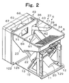
- a genuine coin is guided to a storing bowl 5 of the coin hopper 6 (shown in Fig. 2).
- the coin hopper 6 includes the let off device 9 and the storing bowl 5.
- a supporting board 10 is fixed to frames 11 and 12 which are triangular and are fixed at the ends of a plane board 13.
- the supporting board 10 is rectangular and is slanted at a 60 degrees angle from the plane board 13 and supports the let off device 9.
- a rotating disc 14 is a cylinder with a base that includes a bottom board 15 and a flange 16 which is located at the rim of a bottom board 15. Eight through holes 17 are located at the bottom board 15 at the same distance.
- the rotating disc 14 is fixed on an output shaft 18 of a reducer 19 which is fixed at the rear of the supporting board 10.
- a first electric motor 20 drives the reducer 19.
- the first motor 20 is fixed at the reducer 19.
- the storing bowl 5 includes a base bowl 22 and an increasing bowl 23.
- Base bowl 22 is cylinder like in shape and is fixed at supporting board 10 and encloses rotating disc 14.
- Increasing bowl 23 is rectangular and cylinder like in shape and is fixed at the upper opening 24 of base bowl 22.
- Base bowl 22 is a cylinder with a base that includes a base 25 and an opening 24 of the upper side wall and encloses a rotating disc 14 by the base 25.
- the base 25 is fixed at the supporting board 10.
- a bottom 26 slants parallel to the axis line of the rotating disc 14. The coins 2 slide to the side of the rotating disc 14 on the bottom 26 by gravity.
- a bottom electrode 27 composes of a coin amount sensor 28 (shown in Fig. 10), and is fixed at the bottom 26 near the rotating disc 14.
- a upper electrode 29 is the twin to the bottom electrode 27, and is fixed at the side wall of the base bowl 22.
- the coin amount sensor 28 distinguishes the coins to store in the base bowl 22, because the current flows between bottom electrode 27 and the upper electrode 29.
- the increasing bowl 23 includes a first slanting surface 31 which is located above the rotating disc 14, a second slanting surface 32 and a third slanting surface 33.
- the increasing bowl 23 is funnel form like in shape and it's upper opening is rectangle like in shape.
- the upper opening is a coin entry 34.
- the lower section of the increasing bowl 23 is an exit 35 and is rectangle like in shape.
- the lower section of the increasing bowl 23 is inserted into the opening 24 of the base bowl 22 and is fixed.
- An overflow opening 36 is located at the upper wall of the increasing bowl 23 and faces towards the rotating disc 14.
- the chute 37 is fixed at the side wall of the increased bowl 23.
- the chute 37 is waterchute like in shape and the cross section is rectangle like in shape and has a bottom board 38 and side walls 39 and 40.
- the bottom board 38 slants towards the overflow exit 36 and slants downwards.
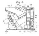
- chute 37 is located in the increased bowl under the top of the increasing bowl 23. (shown in Fig. 8)
- the upper end is an opening 42.
- a coin 2 in the increasing bowl 23 passes through the opening 42 and moves to a chute 41.
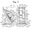
- the auxiliary bowl 43 includes a first auxiliary storing 44, a second auxiliary storing 45 and a recycling device 46. As shown in figure 2, the auxiliary bowl 43 is box like in shape. As shown in figure 7, the auxiliary bowl 43 includes a housing 47, a first cover 48 and a second cover 49.
- a bulkhead 50 is located at the center of the housing 47.
- the bulkhead 50 has a first depressed portion 51 which is located at the side of the storing bowl 5 and a second depressed portion 52 which is located at the opposite side of the hopper 6.
- the first depressed portion 51 is framed in by a first guiding slant 53, a second guiding slant 54, a third guiding slant 55 and a first vertical plane 56.
- the first guiding slant 53 is straight and is located below the overflowing exit 36.
- the second depressed portion 52 is located across from the first guiding slant 53.
- the third guiding slant 55 is continued between the lower section of the first guiding slant 53 and the lower section of the second guiding slant 54.
- the first vertical plane 56 extends vertically from the top section of the first guiding slant 53.
- the first guiding slant 53, the second guiding slant 54 and the third guiding slant 55 together make a "V" in shape.
- the third guiding slant 55 is located at the lower sections of the through hole 57 and the bulkhead 50.
- the lower edge of a through hole 61 is curved which continues to a guiding groove 76.
- the upper edge of the through hole 61 (in other words the lower section 59 of the bulkhead 50 is levelled and straight.
- the third slant 55 slants towards the storing bowl 5 to a rotating belt 60 and downwards. A coin 2 rolls on the third slant 55 by gravity.
- the recycling device 46 includes a delivery device 62 and the transporting device 30.
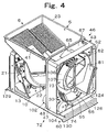
- a delivery device 62 is explained referring to figure 3 through to figure 5 and figure 7.
- a delivery device 62 is located at the upper section of the first depressed portion 51.
- the delivery device 62 compromises a waterchute 63 which is rectangular at the cross section.
- the delivery device 62 crosses the first depressed portion 51 and the second depressed portion 52 and a bottom 64 slants from the second depressed portion 52 to the first depressed portion 51.
- the bottom 64 slants so that the dropped coins slide off by gravity.
- the upper section of the side of the first depressed portion 51 at the waterchute 63 is closed by a guide 65 which is triangular in the cross section.
- An entering coin 2 is guided smoothly to a first-passage 66 or a second passage 67 by the guide 65, because the guide 65 is triangle like in shape.
- first passage 66 is made up between the waterchute 63 and a first vertical wall 56 and a second passage 67 is made up between the waterchute 63 and the second guiding slant 54.
- a straight first cover 48 is put up to the first depressed portion 51 and is fixed at the housing 47 by screws, and covers the first passage 66 and the second passage 67 etc.
- a first auxiliary storing section 68 is the area which is framed in by the first guiding slant 53, the second guiding slant 54 and the third guiding slant 55.
- An opening 69 is located at the first cover 48 opposed to the overflow opening 36 (shown in Figure 8).
- a rectangular opening 70 is made up from the section of the first cover 48 opposed to the opening of the waterchute 63.
- An opening 71 is made up from the section of the increasing bowl 23 opposed to the opening 70.
- the upwards transporting device 30 is located at the second depressed portion 52 and includes the rotating belt 60, a driver 72 of the rotating belt 60 and a supporting device 73.
- the rotating belt 60 is a crawler 74 at this embodiment.
- the crawler device 75 includes a crawler 74 which is made up of many crawler blocks 92, a first guiding groove 76 which goes around at the bulkhead 50 and a second guiding groove 77 which goes around at a second cover 49.
- the first guiding groove 76 is explained referring to figure 5.
- the first guiding groove 76 is oval and made up on the bulkhead 50 of the second depressed section 52.
- the first guiding groove 76 includes an upper curved section 78, a lower curved section 58 which has a smaller curvature than the upper curved section 78, a first slanted section 79 being connected with these curved sections and a second slanted section 80.
- the upper section of the upper curved section 78 is located above the waterchute 63.
- the lower section of the lower curved section 58 is located below the lower end of the third slanted plane.
- a first guiding board 81 is located in the first guiding groove 76 for covering the crawler. The first guiding board 81 separates coins 2 and the crawler 74 which moves downwards.
- the second guiding groove 77 is made up on the inside face of the second cover 49 opposite to the first guiding groove 76 and has the same shape as the first guiding groove 76.
- the second cover 49 is fixed at the housing 47 by a screw, etc.
- the crawler block 92 has four rack tooth 83 on the center of the outer surface.
- a first supporter 84 and a second supporter 85 protrude from both side surfaces of the crawler block 92. Therefore a first depressed section 86 and a second depressed section 87 are made up at both sides of the rack tooth 83.
- a first contacting bar 97 is a round shaft and is located in the first depressed section 86 (which is between the end of the first supporter 84 and the end of the rack tooth 83).
- a second contacting bar 89 is a round shaft and is located in the second depressed section 87 (which is between the end of the first supporter 85 and the end of the rack tooth 83).
- a first connector 94 and a second connector 96 protrude from both side surfaces of the crawler block 92.
- a first connecting groove 93 is U like in shape which is opened outwards and is made up at the end of the first connector 94.
- a second connecting groove 95 is U like in shape which is opened outwards and is made up at the end of the second connector 96.
- a first guide pin 96 protrudes from the first supporter 84 as it is located on an extended line of the first connecting bar 97.
- a second guide pin 98 protrudes from the second supporter 85 as it is located on an extended line of the second connecting bar 89.
- a projection 99 protrudes inside towards the crawler 74 from the lower section of the crawler block 92.
- the projection 99 crosses through the line of rack tooth 83 and has the same width as the crawler block 92.
- the length of the projection 99 is smaller than the thickness of a coin.
- the upper surface of the projection 99 structures a coin-mounting surface 100 at the first slanting section 79. In other words, only one coin is mounted on the projection 99 at the first slanting section 79.
- the crawler block 92 is made up by plastic injection molding. As a result, the crawler block 92 is inexpensive.
- the crawler 74 is made up of many crawler blocks 92 which are chained and have a predetermined length.
- the first connecting bar 97 is inserted in the first connection groove 93 and the second connecting bar 89 is inserted in the second connecting groove 95.
- the predetermined length of the crawler 74 is made up by a predetermined number of crawler blocks 92.
- the rack 46 is made up by rack teeth 83.All first guiding pins 96 are inserted in the first guiding groove 76.
- All second guiding pins 98 are inserted in the second guiding groove 77.
- the second cover 49 is fixed at the housing 47 by screws.
- the second auxiliary storing space 45 is made up by the first guiding plate 59, the lower surface of the crawler 74 and the second cover 49 and is faced to the coin through hole 56.
- the driving device 72 is fixed at the housing 47 and includes a second motor 102, a reducer 103 and a driving gear 104.
- a driving shaft 105 of the reducer 103 is located in the second depressed section 52 and passes through the bulkhead 50 of the housing 47.
- the driving gear 104 is fixed on the driving shaft 105 and is engaged with the rack 46.
- the crawler 74 moves towards the counter in a clockwise direction by the rotation in a counter clockwise direction of the driving gear 104.
- the supporting device 73 includes a supporting board 106 which is located near the left inside of the upper curve 78 and is D like in shape and is elastic.
- a D guide 107 is D like in shape and extends from the bulkhead 50 towards the upper curve 76.
- a first supporting groove 108 is made up by a second guide 109 which is located along a second vertical wall 110 of D guide and extends upwards.
- a second supporting groove 111 is made up between the lower section of the D guide 110 and the second guide 109.
- a third supporting groove 112 is made up by a third guide 113 which is located along the lower edge of the D guide 107 and is levelled.
- a first end 114 extends in the vertical direction at the upper section of the supporting board 106 and is inserted in the first supporting groove 108.
- a second end 115 extends in the vertical direction at the lower section of the supporting board 107 and is inserted in the second supporting groove 111.
- a middle section 116 continues to the second end 115 and is located in the third supporting groove 112.
- the first end 114 of the supporting board 106 has contact with the second guide 109 and the second end 115 has contact with the second vertical wall 110 of D guide 107 and the middle section 116 has contact with the third guide 113 and the projection has contact with the inner surface of the crawler 74.
- the upper end of the supporting board 106 is located near the waterchute 63.
- the supporting board 114 prevents the coins to drop from crawler 74 before the coins are transferred to the waterchute 63.
- the position changing device 120 can change the position between the coin hopper 6 and the auxiliary bowl 43. Therefore, the auxiliary bowl 43 can slide to the coin hopper 6.
- a first mounting device 121 of the position changing device 120 is explained referring to figure 7.
- a first guiding block 122 is located at the lower section of the first cover 48 and is extended towards the level.
- a second guiding block 124 is located at the lower section of the second cover 49 and is extended towards the level.
- a stopper 123 (shown in figure 9) is shaped at the end of the second guiding block 124 and is extended upwards.
- the first guiding block 122 and the second guiding block 124 are located at both sides of the lower section of the auxiliary bowl 43.
- a holder 124 has a first holding channel 125 and a second holding channel 126 which can move sideways and are fixed on the base 13 adjacent to the coin hopper 6.
- the first guiding block 122 is inserted in the first holding channel 125 and the second guiding block 124 is inserted in the second guiding channel 126.
- the first guiding block 122 and the second guiding block 124 can move sideways towards the stopper 123.
- the overflow opening 36 faces the opening 69 of the first cover 48 and the end of the waterchute 63 faces the opening 71 of the increasing bowl 23.
- a second mounting device 128 is explained referring to figure 7.
- a third guiding block 129 is bent from the left end of the base 13 and is extended towards the level.
- a forth guiding block 130 is bent at a right angle on the base 13 and is then extended towards the level.
- a first holding block 130 is crank like in shape and is fixed on the base 132 of a gaming machine; as a result, a third holding channel 133 is formed.
- a second holding block 135 is fixed on the base 132 of a gaming machine; as a result, a fourth holding channel 135 is formed.
- the third guiding block 129 is inserted in the third holding channel 133 and the fourth guiding block 130 is inserted in the fourth holding channel 135.
- the hopper 6 and the auxiliary bowl 43 are moved towards in gaming machine 1. In other words, the hopper 6 and the auxiliary bowl 43 can slide out from gaming machine to the base 13.
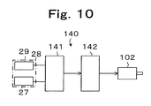
- a control block circuit 140 of the second motor 102 is explained referring to figure 10.
- the bottom electrode 27 and the upper electrode 29 are connected to a distinguishing circuit 141. If a current flows between the bottom electrode 27 and the upper electrode 29, the distinguishing circuit 141 outputs a normal signal. If no current is recognized between the bottom electrode 27 and the upper electrode 29, the distinguishing circuit 141 outputs a defect signal.
- a motor driving circuit 142 drives the second motor 102 as long as it receives the defect signal.
- the auxiliary bowl 43 can be used to store the coins.
- the coins are provided to the first auxiliary bowl 43 through the first passage 66 or the second passage 67.
- a coin 2 which is entered in the coin slot 2 of gaming machine is sent to the increasing bowl 23.
- coins 2 in the increasing bowl 23 move into the overflow chute 37.
- the coins 2 slide on the bottom board 38 and pass through the overflow opening 36 and the opening 69 and drop on the first guiding slanting surface 53 and arrive to the third slanting surface 55.
- the coins 2 slide down on the third slanting surface 55 and arrive on the crawler 74. As a result, coins 2 are stored in the second storing section 45 on the crawler 74. The coins 2 continue to drop on to the crawler 74, and then are piled up higher than the lower edge 59 of the coin passage 56. The coins 2 can not move towards the side of the crawler 74 because of the bulkhead 50, and, as a result, the coins 2 are stored in the first storing section 68.
- the coins 2 slide down on the first guiding slanting surface 53. Therefore, the crawler will not be damaged by the coins dropping down; as a result, the crawler has a long life.
- the first motor 16 rotates and the rotating disc 14 is rotated by the reducer 19.
- the coins 2 are agitated by the rotation of the rotating disc 14, and are changed to the position.
- a coin 2 becomes parallel to the rotating disc 14, the coin 2 drops in through holes 17.
- the coin 2 is supported on the supporting plate 10 and is moved by the pushing tooth (not shown) of the reverse face of rotating disc and is dispensed from the dispensing slot 21 by a known shooting device.
- the coins 2 on the bottom 26 slide downwards and arrive the on the rotating disc 14 and are dispensed from the dispensing slot 21.
- the coins 2 on the first slanting surface 31, the second slanting surface and the third slanting surface 33 of the increasing bowl 23 slide downwards by gravity.
- the coins 2 are levelled lower than the upper electrode 29, no current is recognized between the upper electrode 29 and the bottom electrode 27.
- the distinguished circuit 141 detects and the second motor 102 is rotated by the motor driving circuit 142.
- the crawler 74 moves in the clockwise direction through to the reducer 103, the outputting shaft 105, the driving gear 104 and the rack 46 by the rotation of the second motor 102 as shown in figure 5.
- the coin 2 has contact with the projection 99 of the crawler block 92 and is pushed up at the first slanting section 79.
- the coin 2 does not drop down at the first slanting section 79, because the coin 2 is carried by the crawler block 92.
- the coin 2 is supported by the supporting plate 106. Therefore, the coin 2 is supported by the supporting plate 106 before the coin 2 gets in the vertical situation. As a result, the coin 2 is pressed to the crawler block 92 by the supporting plate 106 and does not drop downwards.
- the middle section 109 of the supporting plate 106 moves towards the right along the third guide 113.
- the middle section 109 is bent to push the coin 2 to the crawler block 92.
- the distance between the crawler 74 and the supporting plate 106 becomes narrow.
- the coin 2 also is pressed to the crawler block 92 by the supporting plate 106.
- the supporting plate 106 continually supports the coin 2, because the upper end is bent downwards in the first supporting groove 108.
- the second motor 102 continues rotating until the current flows between the upper electrode 29 and the bottom electrode 27.
- the coins redemption operation from the hopper 6 and the auxiliary bowl 43 is now explained.
- the front door of the gaming machine 1 is opened.
- the base 13 is pulled out from the gaming machine along the third supporting channel 133 and the fourth supporting channel 135.
- the coins 2 are taken out from the increasing bowl 23 and the base bowl 22.
- the auxiliary bowl 43 is pulled out from the first mounting device 121 along the first supporting channel 125 and the second supporting channel 126 and is detached, as shown in figure 9.
- the auxiliary bowl 43 is inverted to drop the coins 2 from the first auxiliary section 68 and the second auxiliary section 67.
- the coins 2 are redeemed, afterwards the first guiding block 122 is inserted in the first supporting channel 125 and the second guiding block 124 is inserted in the second supporting channel 126 and is moved until the stopper 123 has contact with the second supporting channel 126.
- the base 13 is moved into the gaming machine 1, afterwards the front door is closed.
- the transporting device 30 is moved by the second motor 102. The coins 2 which are dropped from the opening 70 can be redeemed.
- the upwards transporting device 30 is made by a shaft with a spiral.
- the shaft with a spiral rotates around the shaft axis line.
- the coins are held between the spiral and are transported upwards and are transferred to the delivery device.
- the upwards transporting device 30 is made by a rotating disc and a passage which has a cross section of a rectangle. The coins are dispensed into the passage by the rotating disc and are arrayed and are pushed upwards.
- the auxiliary bowl 43 can be locked to the first mounting device 121 or the base 13 by a locking-device. Also, the base can be locked to the gaming machine 1 by a locking device.
- the rotating disc can be made by a rotating disc with some pins which are located at predetermined intervals and are fixed on to the rotating disc.
- the coin volume sensor can be a optical sensor which detects the coins in the base bowl 22.
Landscapes
- Physics & Mathematics (AREA)
- General Physics & Mathematics (AREA)
- Slot Machines And Peripheral Devices (AREA)
- Pinball Game Machines (AREA)
- Control Of Vending Devices And Auxiliary Devices For Vending Devices (AREA)
Claims (8)
- Dispositif de circulation de pièces de monnaie comprenant une trémie pour pièces de monnaie (6) qui a un bol de stockage de pièces de monnaie (5) et un dispositif de décharge (9) pour des pièces de monnaie à l'intérieur de la trémie pour pièces de monnaie,
un bol secondaire (43) qui est situé de manière adjacente à la trémie pour pièces de monnaie,
une ouverture de surplus (36) qui fournit des pièces de monnaie en surplus du bol de stockage de pièces de monnaie (5) au bol secondaire (43),
un dispositif de transport (30) qui transporte les pièces de monnaie du bol secondaire (43) au bol de stockage de pièces de monnaie (5),
un dispositif d'ajustement de position pour modifier la relation de position entre le bol secondaire (43) et le bol de stockage de pièces de monnaie (5),
dans lequel le dispositif d'ajustement de position comprend un premier dispositif de montage (121) qui est situé au niveau d'une base pour le bol secondaire (43) et le bol de stockage de pièces de monnaie (5); de sorte que le bol secondaire (43) puisse coulisser vers l'arrière et vers l'avant sur la base, dans lequel le dispositif de montage (121) est adapté de sorte que le bol secondaire (43) puisse être retiré du premier dispositif de montage (121). - Dispositif de circulation de pièces de monnaie selon la revendication 1, dans lequel le bol secondaire (43) peut être attaché et détaché.
- Dispositif de circulation de pièces de monnaie selon l'une quelconque des revendications 1 à 2, dans lequel ladite base (13) est montée de sorte qu'elle puisse coulisser sur la plaque de base (132) d'une machine de jeu à l'aide d'un second dispositif de montage (128).
- Dispositif de circulation de pièces de monnaie selon la revendication 1, dans lequel le dispositif de transport (30) a un dispositif de transport vers le haut et un dispositif de fourniture.
- Dispositif de circulation de pièces de monnaie selon la revendication 4, dans lequel le dispositif de transport vers le haut est une courroie rotative (60).
- Dispositif de circulation de pièces de monnaie selon la revendication 5, dans lequel la courroie rotative (60) est réalisée à partir de nombreuses chenilles (74).
- Dispositif de circulation de pièces de monnaie selon l'une quelconque des revendications 5 ou 6, comprenant un trou traversant de pièces de monnaie qui est relié à l'ouverture de surplus (36) et qui est situé au niveau de l'extrémité inférieure de la courroie rotative (60).
- Dispositif de circulation de pièces de monnaie selon l'une quelconque des revendications 5 à 7, comprenant un dispositif de support (73) qui pousse les pièces de monnaie sur la courroie rotative (60).
Applications Claiming Priority (2)
| Application Number | Priority Date | Filing Date | Title |
|---|---|---|---|
| JP2001240000A JP4258793B2 (ja) | 2001-08-08 | 2001-08-08 | コインホッパのコイン還流装置 |
| JP2001240000 | 2001-08-08 |
Publications (3)
| Publication Number | Publication Date |
|---|---|
| EP1283505A2 EP1283505A2 (fr) | 2003-02-12 |
| EP1283505A3 EP1283505A3 (fr) | 2005-04-20 |
| EP1283505B1 true EP1283505B1 (fr) | 2006-11-08 |
Family
ID=19070673
Family Applications (1)
| Application Number | Title | Priority Date | Filing Date |
|---|---|---|---|
| EP02017694A Expired - Lifetime EP1283505B1 (fr) | 2001-08-08 | 2002-08-07 | Trémie pour pièces de monnaie dans une machine de jeu |
Country Status (7)
| Country | Link |
|---|---|
| US (1) | US6761627B2 (fr) |
| EP (1) | EP1283505B1 (fr) |
| JP (1) | JP4258793B2 (fr) |
| KR (1) | KR100859678B1 (fr) |
| CN (1) | CN1260688C (fr) |
| DE (1) | DE60215890T2 (fr) |
| ES (1) | ES2276875T3 (fr) |
Cited By (1)
| Publication number | Priority date | Publication date | Assignee | Title |
|---|---|---|---|---|
| EP2226769A1 (fr) | 2009-03-05 | 2010-09-08 | Azkoyen Medios de Pago, S.A. | Distributeur de pièces |
Families Citing this family (16)
| Publication number | Priority date | Publication date | Assignee | Title |
|---|---|---|---|---|
| JP4315274B2 (ja) * | 2003-02-25 | 2009-08-19 | 旭精工株式会社 | コインホッパ |
| US6982040B2 (en) * | 2003-04-16 | 2006-01-03 | Zodiac Pool Care, Inc. | Method and apparatus for purifying water |
| TWD100843S1 (zh) | 2003-06-30 | 2004-10-11 | 旭精工股份有限公司 | 漏斗式接收器 |
| GB2416061A (en) | 2004-07-07 | 2006-01-11 | Money Controls Ltd | Coin accepting and dispensing apparatus |
| ITBO20050768A1 (it) * | 2005-12-16 | 2007-06-17 | Alberici Spa | Dispositivo erogatore di monete |
| WO2008011183A2 (fr) * | 2006-07-21 | 2008-01-24 | Zizzle Llc | Ensemble pour travaux manuels utilisé à des fins de collection et de décoration |
| ITBO20070260A1 (it) * | 2007-04-11 | 2008-10-12 | Otr Tech S R L | Macchina per l'accettazione e la distribuzione di monete e/o di gettoni |
| JP5737887B2 (ja) * | 2010-09-02 | 2015-06-17 | 株式会社タイトー | メダルゲーム機 |
| GB2485395B (en) | 2010-11-12 | 2018-06-27 | Crane Payment Innovations Ltd | Coin apparatus |
| EP2951792B8 (fr) * | 2013-02-04 | 2017-06-07 | Crane Payment Innovations Limited | Transport d'articles de monnaie |
| GB2514156A (en) * | 2013-05-15 | 2014-11-19 | Crane Payment Solutions Ltd | Money item dispensing |
| GB2528287A (en) * | 2014-07-16 | 2016-01-20 | Crane Payment Solutions Ltd | Money item handling device and conveyor |
| GB2533543A (en) * | 2014-07-16 | 2016-06-29 | Crane Payment Solutions Ltd | Conveying money items |
| USD751632S1 (en) * | 2014-09-25 | 2016-03-15 | CoinedBox, Inc. | Coin counting device |
| CN105046818A (zh) * | 2015-08-14 | 2015-11-11 | 湖南金码智能设备制造有限公司 | 一种自动售货机的新式支付系统和方法 |
| GB201915439D0 (en) * | 2019-10-24 | 2019-12-11 | Crane Payment Innovations Ltd | Money item handling system and method |
Family Cites Families (12)
| Publication number | Priority date | Publication date | Assignee | Title |
|---|---|---|---|---|
| DE1499552A1 (de) * | 1965-04-03 | 1971-01-14 | Reis Geb Von Somogyi Csizmazia | Muenzsortier- und Muenzzaehlmaschine |
| JPS55166288U (fr) * | 1979-05-17 | 1980-11-29 | ||
| US4535794A (en) * | 1981-11-20 | 1985-08-20 | Coin Controls Limited | Machine having a coin or token payout mechanism |
| JPS6032983U (ja) * | 1983-08-13 | 1985-03-06 | 株式会社エース電研 | スロツトルマシン |
| JPS6054091A (ja) * | 1983-09-02 | 1985-03-28 | 角野 博光 | ホッパ−型コイン払出機 |
| JPS644841Y2 (fr) * | 1985-03-19 | 1989-02-07 | ||
| US5190495A (en) | 1991-02-14 | 1993-03-02 | Bally Manufacturing Corporation | High capacity coin hopper for a gaming machine |
| JPH04340695A (ja) * | 1991-05-17 | 1992-11-27 | Toshiba Corp | 硬貨処理装置 |
| JP3200502B2 (ja) * | 1993-06-14 | 2001-08-20 | 株式会社オリンピア | スロットマシン |
| JP3983827B2 (ja) * | 1995-06-22 | 2007-09-26 | アルゼ株式会社 | 遊技機用コイン補給及び回収装置 |
| US6200213B1 (en) * | 1998-12-31 | 2001-03-13 | Joseph Cole | Coin delivery, storage and dispensing system for coin operated machines and method for same |
| JP4224838B2 (ja) * | 1999-09-06 | 2009-02-18 | 旭精工株式会社 | コインホッパ |
-
2001
- 2001-08-08 JP JP2001240000A patent/JP4258793B2/ja not_active Expired - Fee Related
-
2002
- 2002-07-31 KR KR1020020045168A patent/KR100859678B1/ko not_active Expired - Fee Related
- 2002-08-06 CN CNB021276625A patent/CN1260688C/zh not_active Expired - Fee Related
- 2002-08-06 US US10/213,318 patent/US6761627B2/en not_active Expired - Fee Related
- 2002-08-07 DE DE60215890T patent/DE60215890T2/de not_active Expired - Lifetime
- 2002-08-07 ES ES02017694T patent/ES2276875T3/es not_active Expired - Lifetime
- 2002-08-07 EP EP02017694A patent/EP1283505B1/fr not_active Expired - Lifetime
Cited By (2)
| Publication number | Priority date | Publication date | Assignee | Title |
|---|---|---|---|---|
| EP2226769A1 (fr) | 2009-03-05 | 2010-09-08 | Azkoyen Medios de Pago, S.A. | Distributeur de pièces |
| ES2374463A1 (es) * | 2009-03-05 | 2012-02-17 | Azkoyen Medio De Pago, S.A. | Dispensador de monedas. |
Also Published As
| Publication number | Publication date |
|---|---|
| DE60215890T2 (de) | 2007-04-12 |
| JP2003051040A (ja) | 2003-02-21 |
| EP1283505A3 (fr) | 2005-04-20 |
| US20030032387A1 (en) | 2003-02-13 |
| KR100859678B1 (ko) | 2008-09-23 |
| CN1405737A (zh) | 2003-03-26 |
| JP4258793B2 (ja) | 2009-04-30 |
| US6761627B2 (en) | 2004-07-13 |
| DE60215890D1 (de) | 2006-12-21 |
| KR20030014581A (ko) | 2003-02-19 |
| CN1260688C (zh) | 2006-06-21 |
| ES2276875T3 (es) | 2007-07-01 |
| EP1283505A2 (fr) | 2003-02-12 |
Similar Documents
| Publication | Publication Date | Title |
|---|---|---|
| EP1283505A2 (fr) | Trémie pour pièces de monnaie dans une machine de jeu | |
| EP1416453B1 (fr) | Machine à sous acceptant des billets | |
| JP2004065834A (ja) | パチンコ機 | |
| JP4693000B2 (ja) | 遊技媒体受容箱及び遊技機 | |
| JP3088639B2 (ja) | 弾球遊技機の通路装置 | |
| US20040129529A1 (en) | Metal bezel for validator | |
| JP4476239B2 (ja) | 遊技機 | |
| JP4222970B2 (ja) | 台間機用遊技メダルの一括投入機構 | |
| JP4476240B2 (ja) | 遊技機 | |
| JP4579176B2 (ja) | メダル送り装置 | |
| JP2000126405A (ja) | パチンコ機 | |
| JP4833344B2 (ja) | 遊技機 | |
| JP2974240B2 (ja) | 弾球遊技機の通路装置 | |
| JP2966319B2 (ja) | 弾球遊技機の通路装置 | |
| JP3088638B2 (ja) | 弾球遊技機の通路装置 | |
| JP2000229160A (ja) | パチンコ機 | |
| JP2004248767A (ja) | メダル貸機 | |
| JP4431100B2 (ja) | メダル送り装置 | |
| JP4579175B2 (ja) | メダル送り装置 | |
| JP4222972B2 (ja) | 遊技機 | |
| JP4131547B2 (ja) | スロットマシン | |
| JP2000153042A (ja) | パチンコ機 | |
| JP2005329077A (ja) | スロットマシン | |
| JPH084652B2 (ja) | パチンコ機の入賞球集合カバー | |
| JP2000202115A (ja) | パチンコ遊技機におけるパチンコ球払出装置の取付構造 |
Legal Events
| Date | Code | Title | Description |
|---|---|---|---|
| PUAI | Public reference made under article 153(3) epc to a published international application that has entered the european phase |
Free format text: ORIGINAL CODE: 0009012 |
|
| AK | Designated contracting states |
Designated state(s): AT BE BG CH CY CZ DE DK EE ES FI FR GB GR IE IT LI LU MC NL PT SE SK TR |
|
| AX | Request for extension of the european patent |
Extension state: AL LT LV MK RO SI |
|
| PUAL | Search report despatched |
Free format text: ORIGINAL CODE: 0009013 |
|
| AK | Designated contracting states |
Kind code of ref document: A3 Designated state(s): AT BE BG CH CY CZ DE DK EE ES FI FR GB GR IE IT LI LU MC NL PT SE SK TR |
|
| AX | Request for extension of the european patent |
Extension state: AL LT LV MK RO SI |
|
| 17P | Request for examination filed |
Effective date: 20050318 |
|
| 17Q | First examination report despatched |
Effective date: 20050523 |
|
| AKX | Designation fees paid |
Designated state(s): DE ES GB |
|
| GRAP | Despatch of communication of intention to grant a patent |
Free format text: ORIGINAL CODE: EPIDOSNIGR1 |
|
| GRAS | Grant fee paid |
Free format text: ORIGINAL CODE: EPIDOSNIGR3 |
|
| GRAA | (expected) grant |
Free format text: ORIGINAL CODE: 0009210 |
|
| AK | Designated contracting states |
Kind code of ref document: B1 Designated state(s): DE ES GB |
|
| REG | Reference to a national code |
Ref country code: GB Ref legal event code: FG4D |
|
| REF | Corresponds to: |
Ref document number: 60215890 Country of ref document: DE Date of ref document: 20061221 Kind code of ref document: P |
|
| REG | Reference to a national code |
Ref country code: ES Ref legal event code: FG2A Ref document number: 2276875 Country of ref document: ES Kind code of ref document: T3 |
|
| PLBE | No opposition filed within time limit |
Free format text: ORIGINAL CODE: 0009261 |
|
| STAA | Information on the status of an ep patent application or granted ep patent |
Free format text: STATUS: NO OPPOSITION FILED WITHIN TIME LIMIT |
|
| 26N | No opposition filed |
Effective date: 20070809 |
|
| PGFP | Annual fee paid to national office [announced via postgrant information from national office to epo] |
Ref country code: ES Payment date: 20090820 Year of fee payment: 8 |
|
| PGFP | Annual fee paid to national office [announced via postgrant information from national office to epo] |
Ref country code: DE Payment date: 20090821 Year of fee payment: 8 Ref country code: GB Payment date: 20090827 Year of fee payment: 8 |
|
| GBPC | Gb: european patent ceased through non-payment of renewal fee |
Effective date: 20100807 |
|
| REG | Reference to a national code |
Ref country code: DE Ref legal event code: R119 Ref document number: 60215890 Country of ref document: DE Effective date: 20110301 |
|
| PG25 | Lapsed in a contracting state [announced via postgrant information from national office to epo] |
Ref country code: DE Free format text: LAPSE BECAUSE OF NON-PAYMENT OF DUE FEES Effective date: 20110301 |
|
| PG25 | Lapsed in a contracting state [announced via postgrant information from national office to epo] |
Ref country code: GB Free format text: LAPSE BECAUSE OF NON-PAYMENT OF DUE FEES Effective date: 20100807 |
|
| REG | Reference to a national code |
Ref country code: ES Ref legal event code: FD2A Effective date: 20111019 |
|
| PG25 | Lapsed in a contracting state [announced via postgrant information from national office to epo] |
Ref country code: ES Free format text: LAPSE BECAUSE OF NON-PAYMENT OF DUE FEES Effective date: 20100808 |