EP1283537B1 - Interrupteur à bascule - Google Patents
Interrupteur à bascule Download PDFInfo
- Publication number
- EP1283537B1 EP1283537B1 EP02255428A EP02255428A EP1283537B1 EP 1283537 B1 EP1283537 B1 EP 1283537B1 EP 02255428 A EP02255428 A EP 02255428A EP 02255428 A EP02255428 A EP 02255428A EP 1283537 B1 EP1283537 B1 EP 1283537B1
- Authority
- EP
- European Patent Office
- Prior art keywords
- contact
- rocker switch
- rocker
- snap
- actuator
- Prior art date
- Legal status (The legal status is an assumption and is not a legal conclusion. Google has not performed a legal analysis and makes no representation as to the accuracy of the status listed.)
- Expired - Lifetime
Links
- 230000000994 depressogenic effect Effects 0.000 claims description 10
- 230000002093 peripheral effect Effects 0.000 claims description 2
- 230000013011 mating Effects 0.000 claims 2
- 230000001419 dependent effect Effects 0.000 description 8
- 230000007246 mechanism Effects 0.000 description 8
- 230000000712 assembly Effects 0.000 description 7
- 238000000429 assembly Methods 0.000 description 7
- 210000003414 extremity Anatomy 0.000 description 7
- 210000003141 lower extremity Anatomy 0.000 description 2
- 238000004519 manufacturing process Methods 0.000 description 2
- 230000000694 effects Effects 0.000 description 1
- 230000003993 interaction Effects 0.000 description 1
- 239000012528 membrane Substances 0.000 description 1
- 239000012815 thermoplastic material Substances 0.000 description 1
Images


Classifications
-
- H—ELECTRICITY
- H01—ELECTRIC ELEMENTS
- H01H—ELECTRIC SWITCHES; RELAYS; SELECTORS; EMERGENCY PROTECTIVE DEVICES
- H01H13/00—Switches having rectilinearly-movable operating part or parts adapted for pushing or pulling in one direction only, e.g. push-button switch
- H01H13/50—Switches having rectilinearly-movable operating part or parts adapted for pushing or pulling in one direction only, e.g. push-button switch having a single operating member
- H01H13/64—Switches having rectilinearly-movable operating part or parts adapted for pushing or pulling in one direction only, e.g. push-button switch having a single operating member wherein the switch has more than two electrically distinguishable positions, e.g. multi-position push-button switches
-
- H—ELECTRICITY
- H01—ELECTRIC ELEMENTS
- H01H—ELECTRIC SWITCHES; RELAYS; SELECTORS; EMERGENCY PROTECTIVE DEVICES
- H01H5/00—Snap-action arrangements, i.e. in which during a single opening operation or a single closing operation energy is first stored and then released to produce or assist the contact movement
- H01H5/04—Energy stored by deformation of elastic members
- H01H5/30—Energy stored by deformation of elastic members by buckling of disc springs
-
- H—ELECTRICITY
- H01—ELECTRIC ELEMENTS
- H01H—ELECTRIC SWITCHES; RELAYS; SELECTORS; EMERGENCY PROTECTIVE DEVICES
- H01H23/00—Tumbler or rocker switches, i.e. switches characterised by being operated by rocking an operating member in the form of a rocker button
- H01H23/28—Tumbler or rocker switches, i.e. switches characterised by being operated by rocking an operating member in the form of a rocker button with three operating positions
- H01H23/30—Tumbler or rocker switches, i.e. switches characterised by being operated by rocking an operating member in the form of a rocker button with three operating positions with stable centre positions and one or both end positions unstable
Definitions
- the present invention relates generally to rocker switches, and more particularly to a new and improved rocker switch which has snap dome contacts incorporated therein so as to provide the rocker switch with a shortened actuation stroke and a tactile feel which is desirable in connection with switch applications which require rapidly or accurately controlled incremental movements in both a positive and negative sense, or in other words, applications which comprise incremental movements in opposite directions.
- Rocker switch assemblies or mechanisms are of course well-known in the electrical switch industry. Examples of rocker switches may be found within US-A-6,066,815 , US-A-5,982,269 , US-A-5,950,812 , US-A-5,865,303 , US-A-5,598,918 , US-A-5,584,380 . Snap-dome contact assemblies are likewise well-known in the industry and have been employed within a wide variety of applications.
- Exemplary snap-dome type contact assemblies are disclosed within US-A-5,999,084 , US-A-5,986,228 , US-A-5,924,555 , US-A-5,898,147 , US-A-4,933,522 , US-A-4,892,988 .
- snap-dome contacts are usually used within panel or membrane type applications.
- rocker switch assemblies and systems while such conventional rocker switches are obviously quite satisfactory with respect to their operation or performance in connection with certain predeterminedly designed modes of operation or applications, the required throw or movement of such rocker switches, when activated for performing, for example, a circuit closure connection, is larger than required or desired for other operative modes or applications, such as for example, small throw and rapidly controllable operational movements for providing operatively associated servo drive mechanisms with rapidly and accurately controllable oppositely oriented incremental movements.
- rocker switches when such rocker switches are to be utilized in connection with the aforenoted small throw, rapidly performed incremental movements, it is also often desired for the operator to experience or receive tactile feedback in order for the operator to properly, suitably, or accurately control the desired implementation of the aforenoted incremental movements as well as to sense the closure of the contact members in order to effectively confirm completion of the contact and the ensuing servo movement.
- a lever or rocker-type switch mechanism or assembly as disclosed within the aforenoted US-A-5598918 comprises a pivotal lever member 104, and a pair of dome switches 122, 124, as specifically disclosed within FIGURE 8A
- the substantially lateral or horizontal movement of the lever member 104, as well as the interdisposition of plunger components 126,128 between the lower end portions of the lever member 104 and the dome switches 122,124 fails to provide or facilitate the necessary tactile feedback back to the operator.
- separate return spring mechanisms or components are often required, and accordingly, the provision of such additional mechanisms or components renders the rocker switch assemblies more expensive to manufacture.
- US 4436970 discloses a rocker switch assembly comprising a housing and a rocker actuator pivotally mounted upon the housing and having integral actuator posts extending towards respective snap contacts that are integral with a first conductive strip disposed above and separated from a second conductive strip having associated flexible contacts.
- a downward depression force on the rocker actuator causes one or other of the actuator posts to depress the respective snap contact to form an electrical contact with the associated flexible contact, with a short throw and providing tactile feedback to the operator.
- EP 0516544 discloses a rocker switch assembly comprising a housing with a rocker actuator pivotally mounted thereon.
- the assembly includes snap-dome contacts that are actuated by downward depression force on the rocker actuator.
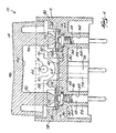
- rocker switch assembly is disclosed and is generally indicated by the reference character 10.
- the rocker switch assembly 10 is seen to comprise a rocker switch housing 12 and a rocker switch actuator 14 wherein the rocker switch actuator 14 is pivotally mounted upon upper end portions of oppositely disposed side walls 16 of the rocker switch housing 12.
- each one of the upper end portions of the oppositely disposed side walls 16 of the rocker switch housing 12 is provided with a through-aperture 18, and the oppositely disposed side walls 20 of the rocker switch actuator 14 are respectively provided with coaxially disposed oppositely extending trunnions 22 wherein the trunnions 22 are adapted to be snap-fitted within the through-apertures 18 of rocker switch housing side walls 16.
- both the rocker switch housing 12 and the rocker switch actuator 14 may be fabricated from a suitable thermoplastic material.
- the rocker switch housing 12 further comprises a horizontally extending floor or foundation portion 24 which is located at a substantially central elevational level as considered along the vertical extent or height dimension of the rocker switch housing 12, and it is seen that a pair of dependent tubular posts 26,28 project downwardly from an undersurface portion 30 of the floor or foundation 24 so as to respectively define a pair of through-bores 32,34 therethrough.
- Upper end portions of the through-bores 32,34 are countersunk, as at 36,38, within an upper surface portion 40 of the floor or foundation 24, and a pair of first and second electrical circuit contact pins 42,44 are respectively disposed within the through-bores 32,34 of the dependent tubular posts 26,28.
- each one of the through-bores 32,34 defined within the dependent tubular posts 26,28 has a predetermined diametrical extent
- the primary shank portion of each electrical circuit contact pin 42,44 has a diametrical extent which is just slightly less than that of its respective through-bore 32,34.
- the primary shank portion of each electrical circuit contact pin 42,44 is provided, however, with a radially outwardly projecting annular rib member 46,48 whereby the first and second electrical circuit contact pins 42,44 are disposed and fixedly mounted within the respective bores 32,34 of the dependent tubular posts 26,28 through means of a press-fit or an interference fit.
- the countersunk portions 36,38 of the through-bores 32,34 define shoulder portions 50,52 upon which flanged head portions 54,56 of the first and second electrical circuit contact pins 42,44 are adapted to be seated when the first and second electrical circuit contact pins 42,44 are fully and properly mounted within the rocker switch housing 12.
- the rocker switch housing floor or foundation 24 is provided with a pair of transversely spaced upstanding posts 58,60, and a common or ground plate 62 is adapted to be fixedly mounted and supported upon the upper surface portion 40 of the floor or foundation 24 as a result of being disposed and fitted upon the upstanding posts 58,60.
- the ground plate 62 is provided with a first set of apertures 64,66 which are transversely spaced from each other by means of a center-to-center distance which substantially corresponds to the transverse spacing of the upstanding posts 58,60 of the rocker switch housing 12, and it is noted that the diametrical extent of each aperture 64,66 is substantially the same as the diametrical extent of each upstanding post 58,60.
- Each one of the upstanding posts 58,60 is provided with a circumferentially spaced array of crush ribs 68,70, and in this manner, when the ground plate 62 is to be mounted upon the floor or foundation 24 of the rocker switch housing 12, the apertures 64,66 of the ground plate 62 are coaxially aligned with the upstanding posts 58, 60, the ground plate 62 is then moved downwardly so as to effectively insert the upstanding posts 58,60 through the ground plate apertures 64,66, and accordingly, the interaction of the peripheral portions of the ground plate apertures 64,66 with the crush ribs 68,70 defines an interference or press fit between each apertured portion of the ground plate 62 and its upstanding mounting post 58,60.
- the floor or foundation portion 24 of the rocker switch housing 12 is provided with a third downwardly extending dependent post member 72 which is located at a transversely central location along the rear wall of the switch housing 12 and which has a substantially rectangular cross-sectional configuration as can best be appreciated from FIGURE 3 .
- the interior portion of the post member 72 is provided with a substantially key-shaped slot 74, and the ground plate 62 is provided with an integrally formed, downwardly extending dependent ground pin 76 which is therefore adapted to be disposed within the key-shaped slot 74 of the post member 72 when the ground plate 62 is fixedly mounted upon the rocker switch housing 12 through means of the aforenoted interference or press fit defined between the upstanding mounting posts 58,60 and the apertured portions 64,66 of the ground plate 62.
- the upper surface portion 40 of the floor or foundation portion 24 of rocker switch housing 12 is further provided with a plurality of upstanding scallop-shaped members 78,80 upon opposite end, and front wall and rear wall, regions thereof.
- oppositely disposed, transversely spaced end portions of the ground plate 62 have scallop-shaped or arcuate regions 82,84 punched or cut out from opposite end, and front wall and rear wall, regions thereof.
- the ground plate 62 when the ground plate 62 is mounted upon the floor or foundation portion 24 of the rocker switch housing 12 as a result of being fixedly mounted upon the upstanding mounting posts 58,60 through means of the aforenoted interference or press fittings as defined between the apertured portions 64,66 of the ground plate 62 and the upstanding mounting posts 58,60, the scalloped or arcuate-shaped portions 82,84 of the ground plate 62 will likewise be operatively disposed and properly seated or mated with the scallop-shaped members 78,80 of the rocker switch housing 12.
- a pair of snap-dome contacts 86,88 are adapted to be mounted within the rocker switch housing 12 so as to be operatively associated with the first and second electrical circuit contact pins 42,44.
- the rocker switch actuator 14 is provided with a pair of transversely spaced dependent actuator posts 90,92 which extend vertically downwardly from an undersurface interior surface portion 94 of an operator-actuated plate portion 96.
- each one of the snap-dome contacts 86,88 has a substantially X-shaped or +-shaped configuration wherein each side of the contact 86 or 88 has a scalloped or arcuately-shaped cut-out or punched-out region 106,108, and a leg member 110,112 defined within corner regions of each snap-dome contact 86,88.
- the leg members 110,112 will support the snap-dome contacts 86,88 upon the upper surface portion of the ground plate 62, and forward and backward, as well as transverse movements of the snap-dome contacts 86,88 will effectively be prevented as a result of the cooperative engagement of the scalloped side portions 106,108 of the snap-dome contacts with the upstanding scallop-shaped members 78,80 of the rocker switch housing 12 as well as the upstanding mounting posts 58,60.
- ground plate 62 is electrically isolated from the first and second electrical circuit contact pins 42,44, other than when a particular one of two electrical circuits is to be defined or CLOSED between the ground pin 76-ground plate 62 and one of the first and second electrical circuit contact pins 42,44 through the intermediary of a respective one of the snap-dome contacts 86,88, it is noted that the ground plate 62 is further provided with a pair of apertures 114,116 through which the upper end portions of the first and second electrical circuit contact pins 42,44 can freely project as best seen in FIGURE 1 .
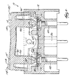
- FIGURE 2 With reference now being made to FIGURE 2 , the operation of the new and improved rocker switch assembly 10, constructed in accordance with the principles and teachings of the present invention, will now be described.
- the rocker switch actuator 14 is normally disposed in its non-tilted, non-actuated and centered position or state, as also shown in FIGURE 1 , as a result of both of the snap-dome contacts 86,88 biasing the rocker switch actuator 14 with equalized forces as transmitted to the rocker switch actuator 14 from the snap-dome contacts 86,88 through means of the actuator posts 90,92.
- both of the snap-dome contacts 86,88 are disposed out of contact with respect to their respective first and second electrical circuit contact pins 42,44 whereby the first and second electrical circuits are disposed in an OPEN state.
- the upper surface portion of the rocker switch actuator 14 comprises two oppositely inclined substantially planar fingertip engagement portions 118,120 for facilitating actuation of the rocker switch actuator 14.
- the rocker switch actuator 14 when, for example, the rocker switch actuator 14 is rocked pivoted, or tilted in the clockwise direction about its trunnions 22 as a result of a downward depression force being impressed upon the right fingertip engagement portion 120 of the actuator 14 so as to be disposed at the position 14', the right actuator post 92 will be accordingly tilted to the position shown at 92', but most importantly, the lower end extremity portion 100 of the actuator post 92 will be moved substantially vertically downwardly from the position shown at 100 to that shown at 100' whereby such lower end extremity portion 100 of the rocker actuator post 92 will now force the elevated central portion 104 of the snap-dome contact 88 to move downwardly into engagement with the upper end extremity portion of the electrical circuit contact pin 44.
- the particular electrical circuit controlled by means of electrical circuit contact pin 44 is now disposed in its CLOSED state whereby, for example, an incremental servo or similar movement can be achieved.
- the other actuator post 90 is moved correspondingly upwardly to the position 90' whereby the lower end extremity portion 98 of the actuator post 90 is now disposed entirely out of contact with, or disengaged from, the snap-dome contact 86.
- the electrical circuit therefore controlled by means of electrical circuit contact pin 42 remains in its CLOSED state.
- opposite servo movements that is, upward or downward, forward or backward, positive or negative, may be respectively controlled by means of the first and second electrical circuits which are in turn respectively controlled by means of the electrical circuit contact pins 42,44 and their respective electrical connections to the common or ground contact pin 76 through means of the ground plate 62 and the respective snap-dome contacts 86,88.
- the new and improved rocker switch assembly 10 which is constructed in accordance with the principles and teachings of the present invention, is able to achieve rapid and accurate incremental servo movements due to the small throw or degree of movement achieved by means of the rocker assembly actuator 14 during a depression actuation or operation, as well as the tactile feedback provided to the operator so as to confirm in effect that a CLOSED state for a particular electrical circuit controlled by means of either one of the electrical circuit contact pins 42,44 has in fact been achieved.
- the small throw or degree of movement of the actuator 14, as well as the tactile feedback of the switch and circuit closure is, in turn, achieved as a result of several structural factors unique to the arrangement of the component parts of the rocker switch assembly 10 of the present invention.
- the relatively small vertical throw or movement of the rocker actuator 14, and in particular, the throw or movement of the actuator posts 90,92 resides in the fact that the actuator posts 90, 92 are integral with the actuator plate portion 96, that the actuator posts 90,92 extend vertically downwardly from the actuator plate portion 96, and that the lower end extremity portions 98,100 are normally disposed in contact or engagement with the snap-dome contacts 86,88. No separate return spring elements or components are or need be interposed between the actuator posts 90,92 and the snap-dome contacts 86,88 or the electrical circuit contact pins 42,44.
- the substantial vertical alignment of the actuator posts 90,92, the elevated central portions 102,104 of the snap-dome contacts 86,88, and the electrical circuit contact pins 42,44, and the relative vertical movement of the actuator posts 90,92 and the elevated central portions 102,104 of the snap-dome contacts 86,88 with respect to the upper end extremity portions of the electrical circuit contact pins 42,44 serves to provide the operator with requisite degree of tactile feedback which is absolutely required in order to achieve the aforenoted rapid and accurate incremental servo movements.
Landscapes
- Push-Button Switches (AREA)
- Tumbler Switches (AREA)
- Switches With Compound Operations (AREA)
- Switch Cases, Indication, And Locking (AREA)
Claims (5)
- Interrupteur à bascule (10) comprenant :un boîtier d'interrupteur à bascule (12) ;un contact avec la terre (62) et une broche de contact avec circuit électrique (50, 52) montés de manière fixe à l'intérieur dudit boîtier d'interrupteur à bascule (12), ledit contact avec la terre (62) et ladite broche de contact avec circuit électrique (50, 52) étant normalement électriquement dégagés l'un de l'autre, ledit contact avec la terre (62) comprenant une broche de contact avec la terre (76) et une plaque de terre (62) ;un contact à dôme à action brusque (86, 88) monté à l'intérieur dudit boîtier d'interrupteur à bascule (12) de façon à ce qu'une partie périphérique de celui-ci soit normalement disposée en contact électrique avec ledit contact avec la terre (62) tandis qu'une partie élevée centrale (98, 100) du contact à dôme à action brusque est normalement dégagée électriquement de ladite broche de contact avec circuit électrique (50, 52) ;un actionneur à bascule (14) monté de manière pivotante sur ledit boîtier d'interrupteur à bascule (12) et comprenant une partie plaque à bascule (96) ;un montant d'actionneur (90, 92) solidaire de ladite partie plaque à bascule (96) et s'étendant vers ladite broche de contact (50, 52) de façon à ce qu'une partie extrême libre dudit montant d'actionneur soit normalement disposée en contact avec ladite partie élevée centrale (98, 100) dudit contact à dôme à action brusque (86, 88), ce qui fait que, lorsque ladite partie élevée centrale (98, 100) dudit contact à dôme à action brusque (86, 88) est disposée dans un état normal non enfoncé, ladite partie centrale élevée (98, 100) de celui-ci sollicite ledit actionneur d'interrupteur à bascule (14) pour qu'il retourne dans une position normale non enfoncée, et ce qui fait que, lorsqu'une force d'enfoncement vers le bas est appliquée sur ledit actionneur d'interrupteur à bascule (14), ladite portion extrême dudit montant d'actionneur (90, 92) fait en sorte que ladite partie centrale élevée (98, 100) dudit contact à dôme à action brusque (86, 88) soit enfoncée de manière à entrer en contact avec ladite broche de contact avec circuit électrique (50, 52) au moyen d'une petite course d'actionnement de façon à connecter électriquement ledit contact avec la terre (62) à ladite broche de contact avec circuit électrique (50, 52), lequel contact peut être détecté par un opérateur au moyen d'une réaction tactile à travers ledit montant d'actionneur (90, 92) ;une partie sol (24) formée solidairement à l'intérieur dudit boîtier d'interrupteur à bascule (12) ;une paire de montants verticaux (58, 60) formés solidairement sur ladite partie sol (24) dudit boîtier d'interrupteur à bascule (12) ; etune paire de premières ouvertures (64, 66) définies à l'intérieur de ladite plaque de terre (62) pour s'accoupler avec ladite paire de montants verticaux (58, 60) formés sur ladite partie sol (24) dudit boîtier d'interrupteur à bascule (12) de façon à établir un ajustement avec serrage avec celles-ci, grâce à quoi ladite plaque de terre (62) est attachée de manière fixe à l'intérieur dudit boîtier d'interrupteur à bascule (12) ;dans lequel :ladite partie sol (24) dudit boîtier d'interrupteur à bascule (12) comprend une pluralité d'éléments parois à formes de coquilles (78, 80) ;ladite plaque de terre (62) comprend une pluralité de régions découpées à formes de coquilles correspondantes (82, 84) pour s'accoupler avec lesdits éléments parois à formes de coquilles (78, 80) de ladite partie sol (24) dudit boîtier d'interrupteur à bascule (12), ce qui fait que ladite plaque de terre (62) est montée sur ladite partie sol (24) dudit boîtier d'interrupteur à bascule d'une manière limitée positionnellement ; etle ou chaque contact à dôme à action brusque (86, 88) a une configuration essentiellement en forme de X ; comprenant :une pluralité de parties latérales à formes de coquilles (106, 108) pour coopérer positionnellement avec lesdits éléments parois à formes de coquilles (78, 80) de ladite partie sol (24) dudit boîtier d'interrupteur à bascule (12) ; etune pluralité d'éléments pattes (110, 112) formés à l'intérieur de régions en coin du ou de chaque contact à dôme à action brusque essentiellement en forme de X (86, 88) pour supporter le ou chaque contact à dôme à action brusque essentiellement en forme de X (86, 88) sur ladite plaque de terre (62).
- Ensemble interrupteur à bascule selon la revendication 1, comprenant :une première et une deuxième broche de contact avec circuit électrique (50, 52) montées de manière fixe à l'intérieur du boîtier d'interrupteur à bascule ; un premier et un deuxième contact à dôme à action brusque (86, 88) montés à l'intérieur dudit boîtier d'interrupteur à bascule (12) et associés aux broches respectives desdites première et deuxième broches de contact avec circuit électrique (50, 52) ;ledit actionneur à bascule (14) comprenant deux montants d'actionneur (90, 92) sur des côtés opposés du pivot et associés aux contacts à dôme à action brusque respectifs (86, 88) de façon à ce qu'une partie extrême de chacun desdits premier et deuxième montants d'actionneur (90, 92) soit normalement disposée en contact avec ladite partie centrale élevée (98, 100) de leurs contacts à dôme à action brusque respectifs (86, 88), ce qui fait que, lorsque lesdites parties élevées centrales (98, 100) des deux desdits premier et deuxième contacts à dôme à action brusque (86, 88) sont disposées dans un état normal, non enfoncé, elles sollicitent ledit actionneur à bascule (14) vers une position centrale normale, non enfoncée, dans laquelle les deux desdits contacts à dôme à action brusque (86, 88) sont électriquement dégagés de leurs broches de contact respectives (50, 52), et ce qui fait que, quand une force d'enfoncement vers le bas est appliquée sur une ou l'autre extrémité de ladite partie plaque à bascule (96) dudit actionneur à bascule (14), ladite partie extrême d'un desdits premier et deuxième montants d'actionneur (90, 92) fait en sorte que ladite partie élevée centrale (98, 100) de son contact à dôme à action brusque respectif (86, 88) soit enfoncée de manière à la mettre en contact avec ses broches de contact avec circuit électrique respectives (50, 52).
- Ensemble interrupteur à bascule selon la revendication 1 ou 2, dans lequel :chacun de ladite paire de montants verticaux (58, 60) formés solidairement sur ladite partie sol (24) dudit boîtier d'interrupteur à bascule (12) comprend une pluralité de nervures à écrasement (68, 70) pour interagir avec lesdites ouvertures (64, 66) de ladite plaque de terre (62) de façon à définir ledit ajustement avec serrage entre ladite plaque de terre (62) et ladite paire de montants verticaux (58, 60).
- Ensemble interrupteur à bascule selon l'une quelconque des revendications précédentes, dans lequel :ladite partie sol (24) comprend une paire de montants tubulaires s'étendant vers le bas (26, 28, 72) pour y loger ladite broche de contact avec la terre (76) et au moins une broche de contact avec circuit électrique (50, 52).
- Ensemble interrupteur à bascule selon l'une quelconque des revendications précédentes, dans lequel :ladite plaque de terre (62) est pourvue d'une deuxième ouverture qui entoure annulairement une partie extrême supérieure de la ou de chaque broche de contact avec circuit électrique (50, 52) et qui a une étendue diamétrale qui est plus grande que celle de ladite partie extrême supérieure de la ou de chaque broche de contact avec circuit électrique (50, 52) de façon à ce que ladite plaque de terre soit normalement déconnectée électriquement de la ou de chaque broche de contact avec circuit électrique (50, 52).
Applications Claiming Priority (2)
| Application Number | Priority Date | Filing Date | Title |
|---|---|---|---|
| US925387 | 2001-08-09 | ||
| US09/925,387 US6545239B2 (en) | 2001-08-09 | 2001-08-09 | Rocker switch with snap dome contacts |
Publications (2)
| Publication Number | Publication Date |
|---|---|
| EP1283537A1 EP1283537A1 (fr) | 2003-02-12 |
| EP1283537B1 true EP1283537B1 (fr) | 2010-10-06 |
Family
ID=25451670
Family Applications (1)
| Application Number | Title | Priority Date | Filing Date |
|---|---|---|---|
| EP02255428A Expired - Lifetime EP1283537B1 (fr) | 2001-08-09 | 2002-08-02 | Interrupteur à bascule |
Country Status (6)
| Country | Link |
|---|---|
| US (1) | US6545239B2 (fr) |
| EP (1) | EP1283537B1 (fr) |
| JP (1) | JP3999597B2 (fr) |
| KR (1) | KR100922340B1 (fr) |
| DE (1) | DE60237865D1 (fr) |
| TW (1) | TW554363B (fr) |
Families Citing this family (116)
| Publication number | Priority date | Publication date | Assignee | Title |
|---|---|---|---|---|
| US7435249B2 (en) | 1997-11-12 | 2008-10-14 | Covidien Ag | Electrosurgical instruments which reduces collateral damage to adjacent tissue |
| US6726686B2 (en) | 1997-11-12 | 2004-04-27 | Sherwood Services Ag | Bipolar electrosurgical instrument for sealing vessels |
| US6228083B1 (en) | 1997-11-14 | 2001-05-08 | Sherwood Services Ag | Laparoscopic bipolar electrosurgical instrument |
| US7364577B2 (en) | 2002-02-11 | 2008-04-29 | Sherwood Services Ag | Vessel sealing system |
| US7118570B2 (en) | 2001-04-06 | 2006-10-10 | Sherwood Services Ag | Vessel sealing forceps with disposable electrodes |
| US7582087B2 (en) | 1998-10-23 | 2009-09-01 | Covidien Ag | Vessel sealing instrument |
| US7267677B2 (en) | 1998-10-23 | 2007-09-11 | Sherwood Services Ag | Vessel sealing instrument |
| US20030109875A1 (en) * | 1999-10-22 | 2003-06-12 | Tetzlaff Philip M. | Open vessel sealing forceps with disposable electrodes |
| AU2001249933B2 (en) | 2001-04-06 | 2006-06-08 | Covidien Ag | Vessel sealer and divider with non-conductive stop members |
| EP1527747B1 (fr) | 2001-04-06 | 2015-09-30 | Covidien AG | Instrument électro-chirurgical réduisant les dégats collatéraux des tissus adjacents |
| US7535454B2 (en) * | 2001-11-01 | 2009-05-19 | Immersion Corporation | Method and apparatus for providing haptic feedback |
| US7276068B2 (en) | 2002-10-04 | 2007-10-02 | Sherwood Services Ag | Vessel sealing instrument with electrical cutting mechanism |
| US7270664B2 (en) | 2002-10-04 | 2007-09-18 | Sherwood Services Ag | Vessel sealing instrument with electrical cutting mechanism |
| US7931649B2 (en) | 2002-10-04 | 2011-04-26 | Tyco Healthcare Group Lp | Vessel sealing instrument with electrical cutting mechanism |
| US7799026B2 (en) | 2002-11-14 | 2010-09-21 | Covidien Ag | Compressible jaw configuration with bipolar RF output electrodes for soft tissue fusion |
| US7776036B2 (en) | 2003-03-13 | 2010-08-17 | Covidien Ag | Bipolar concentric electrode assembly for soft tissue fusion |
| WO2004098383A2 (fr) | 2003-05-01 | 2004-11-18 | Sherwood Services Ag | Instrument electrochirurgical reduisant les dommages thermiques causes aux tissus adjacents |
| US7160299B2 (en) | 2003-05-01 | 2007-01-09 | Sherwood Services Ag | Method of fusing biomaterials with radiofrequency energy |
| CA2525785C (fr) | 2003-05-15 | 2013-03-12 | Sherwood Services Ag | Dispositif de scellement de tissu dote d'elements d'arret variables non conducteurs et procede de scellement de tissu |
| US7156846B2 (en) | 2003-06-13 | 2007-01-02 | Sherwood Services Ag | Vessel sealer and divider for use with small trocars and cannulas |
| US7857812B2 (en) | 2003-06-13 | 2010-12-28 | Covidien Ag | Vessel sealer and divider having elongated knife stroke and safety for cutting mechanism |
| USD956973S1 (en) | 2003-06-13 | 2022-07-05 | Covidien Ag | Movable handle for endoscopic vessel sealer and divider |
| US7150749B2 (en) | 2003-06-13 | 2006-12-19 | Sherwood Services Ag | Vessel sealer and divider having elongated knife stroke and safety cutting mechanism |
| GB2404495A (en) * | 2003-07-30 | 2005-02-02 | Delphi Tech Inc | Rocker switch |
| US9848938B2 (en) | 2003-11-13 | 2017-12-26 | Covidien Ag | Compressible jaw configuration with bipolar RF output electrodes for soft tissue fusion |
| US7367976B2 (en) | 2003-11-17 | 2008-05-06 | Sherwood Services Ag | Bipolar forceps having monopolar extension |
| US7811283B2 (en) | 2003-11-19 | 2010-10-12 | Covidien Ag | Open vessel sealing instrument with hourglass cutting mechanism and over-ratchet safety |
| US7131970B2 (en) | 2003-11-19 | 2006-11-07 | Sherwood Services Ag | Open vessel sealing instrument with cutting mechanism |
| US7500975B2 (en) | 2003-11-19 | 2009-03-10 | Covidien Ag | Spring loaded reciprocating tissue cutting mechanism in a forceps-style electrosurgical instrument |
| US7442193B2 (en) | 2003-11-20 | 2008-10-28 | Covidien Ag | Electrically conductive/insulative over-shoe for tissue fusion |
| US7780662B2 (en) | 2004-03-02 | 2010-08-24 | Covidien Ag | Vessel sealing system using capacitive RF dielectric heating |
| US7439832B1 (en) | 2004-03-16 | 2008-10-21 | Pass & Seymour, Inc. | Electrical wiring device switch assembly and combination device with circuit protection component |
| US6930269B1 (en) | 2004-06-28 | 2005-08-16 | Eaton Corporation | Quiet, medium current rocker switch |
| JP2006032059A (ja) * | 2004-07-14 | 2006-02-02 | Tokai Rika Co Ltd | スイッチ装置 |
| US7195631B2 (en) | 2004-09-09 | 2007-03-27 | Sherwood Services Ag | Forceps with spring loaded end effector assembly |
| US7540872B2 (en) | 2004-09-21 | 2009-06-02 | Covidien Ag | Articulating bipolar electrosurgical instrument |
| US7955332B2 (en) | 2004-10-08 | 2011-06-07 | Covidien Ag | Mechanism for dividing tissue in a hemostat-style instrument |
| US7026565B1 (en) | 2004-12-27 | 2006-04-11 | Eaton Corporation | Self-contained actuator subassembly for a rocker switch and rocker switch employing the same |
| US7909823B2 (en) | 2005-01-14 | 2011-03-22 | Covidien Ag | Open vessel sealing instrument |
| US7686804B2 (en) | 2005-01-14 | 2010-03-30 | Covidien Ag | Vessel sealer and divider with rotating sealer and cutter |
| US7491202B2 (en) | 2005-03-31 | 2009-02-17 | Covidien Ag | Electrosurgical forceps with slow closure sealing plates and method of sealing tissue |
| US7173206B2 (en) * | 2005-04-22 | 2007-02-06 | Tyco Electronics Canada Ltd. | Sealed soft switch assemblies |
| US7105762B1 (en) | 2005-06-07 | 2006-09-12 | Eaton Corporation | Rocker switch and actuator therefor |
| US7722607B2 (en) | 2005-09-30 | 2010-05-25 | Covidien Ag | In-line vessel sealer and divider |
| ES2381560T3 (es) | 2005-09-30 | 2012-05-29 | Covidien Ag | Funda aislante para fórceps electroquirúrgicos |
| US7879035B2 (en) | 2005-09-30 | 2011-02-01 | Covidien Ag | Insulating boot for electrosurgical forceps |
| US7789878B2 (en) | 2005-09-30 | 2010-09-07 | Covidien Ag | In-line vessel sealer and divider |
| CA2561034C (fr) | 2005-09-30 | 2014-12-09 | Sherwood Services Ag | Catheter endoscopique flexible avec un effecteur terminal pouvant coaguler et couper les tissus |
| US7922953B2 (en) | 2005-09-30 | 2011-04-12 | Covidien Ag | Method for manufacturing an end effector assembly |
| US8298232B2 (en) | 2006-01-24 | 2012-10-30 | Tyco Healthcare Group Lp | Endoscopic vessel sealer and divider for large tissue structures |
| US8241282B2 (en) * | 2006-01-24 | 2012-08-14 | Tyco Healthcare Group Lp | Vessel sealing cutting assemblies |
| US8882766B2 (en) | 2006-01-24 | 2014-11-11 | Covidien Ag | Method and system for controlling delivery of energy to divide tissue |
| US8734443B2 (en) | 2006-01-24 | 2014-05-27 | Covidien Lp | Vessel sealer and divider for large tissue structures |
| US7674003B2 (en) * | 2006-04-20 | 2010-03-09 | Streamlight, Inc. | Flashlight having plural switches and a controller |
| US7776037B2 (en) | 2006-07-07 | 2010-08-17 | Covidien Ag | System and method for controlling electrode gap during tissue sealing |
| FR2904442B1 (fr) * | 2006-07-31 | 2009-01-09 | Archos Sa | "clavier, et appareil video compact ainsi equipe dote d'un ecran" |
| US8597297B2 (en) | 2006-08-29 | 2013-12-03 | Covidien Ag | Vessel sealing instrument with multiple electrode configurations |
| US8070746B2 (en) | 2006-10-03 | 2011-12-06 | Tyco Healthcare Group Lp | Radiofrequency fusion of cardiac tissue |
| USD649249S1 (en) | 2007-02-15 | 2011-11-22 | Tyco Healthcare Group Lp | End effectors of an elongated dissecting and dividing instrument |
| US20080237009A1 (en) * | 2007-03-27 | 2008-10-02 | Adam Weisz-Margulescu | Sealed switch assembly |
| US8267935B2 (en) | 2007-04-04 | 2012-09-18 | Tyco Healthcare Group Lp | Electrosurgical instrument reducing current densities at an insulator conductor junction |
| US20090082766A1 (en) * | 2007-09-20 | 2009-03-26 | Tyco Healthcare Group Lp | Tissue Sealer and End Effector Assembly and Method of Manufacturing Same |
| US7877853B2 (en) | 2007-09-20 | 2011-02-01 | Tyco Healthcare Group Lp | Method of manufacturing end effector assembly for sealing tissue |
| US7877852B2 (en) | 2007-09-20 | 2011-02-01 | Tyco Healthcare Group Lp | Method of manufacturing an end effector assembly for sealing tissue |
| US8236025B2 (en) | 2007-09-28 | 2012-08-07 | Tyco Healthcare Group Lp | Silicone insulated electrosurgical forceps |
| US8235993B2 (en) | 2007-09-28 | 2012-08-07 | Tyco Healthcare Group Lp | Insulating boot for electrosurgical forceps with exohinged structure |
| US8251996B2 (en) | 2007-09-28 | 2012-08-28 | Tyco Healthcare Group Lp | Insulating sheath for electrosurgical forceps |
| US8221416B2 (en) | 2007-09-28 | 2012-07-17 | Tyco Healthcare Group Lp | Insulating boot for electrosurgical forceps with thermoplastic clevis |
| US9023043B2 (en) | 2007-09-28 | 2015-05-05 | Covidien Lp | Insulating mechanically-interfaced boot and jaws for electrosurgical forceps |
| US8235992B2 (en) | 2007-09-28 | 2012-08-07 | Tyco Healthcare Group Lp | Insulating boot with mechanical reinforcement for electrosurgical forceps |
| AU2008221509B2 (en) | 2007-09-28 | 2013-10-10 | Covidien Lp | Dual durometer insulating boot for electrosurgical forceps |
| US8267936B2 (en) | 2007-09-28 | 2012-09-18 | Tyco Healthcare Group Lp | Insulating mechanically-interfaced adhesive for electrosurgical forceps |
| US7652216B2 (en) | 2007-12-18 | 2010-01-26 | Streamlight, Inc. | Electrical switch, as for controlling a flashlight |
| US8764748B2 (en) | 2008-02-06 | 2014-07-01 | Covidien Lp | End effector assembly for electrosurgical device and method for making the same |
| US8623276B2 (en) | 2008-02-15 | 2014-01-07 | Covidien Lp | Method and system for sterilizing an electrosurgical instrument |
| US8469956B2 (en) | 2008-07-21 | 2013-06-25 | Covidien Lp | Variable resistor jaw |
| US8257387B2 (en) | 2008-08-15 | 2012-09-04 | Tyco Healthcare Group Lp | Method of transferring pressure in an articulating surgical instrument |
| US8162973B2 (en) | 2008-08-15 | 2012-04-24 | Tyco Healthcare Group Lp | Method of transferring pressure in an articulating surgical instrument |
| US9603652B2 (en) | 2008-08-21 | 2017-03-28 | Covidien Lp | Electrosurgical instrument including a sensor |
| US8784417B2 (en) | 2008-08-28 | 2014-07-22 | Covidien Lp | Tissue fusion jaw angle improvement |
| US8795274B2 (en) | 2008-08-28 | 2014-08-05 | Covidien Lp | Tissue fusion jaw angle improvement |
| US8317787B2 (en) | 2008-08-28 | 2012-11-27 | Covidien Lp | Tissue fusion jaw angle improvement |
| US8303582B2 (en) | 2008-09-15 | 2012-11-06 | Tyco Healthcare Group Lp | Electrosurgical instrument having a coated electrode utilizing an atomic layer deposition technique |
| US20100069903A1 (en) * | 2008-09-18 | 2010-03-18 | Tyco Healthcare Group Lp | Vessel Sealing Instrument With Cutting Mechanism |
| US8535312B2 (en) | 2008-09-25 | 2013-09-17 | Covidien Lp | Apparatus, system and method for performing an electrosurgical procedure |
| US9375254B2 (en) | 2008-09-25 | 2016-06-28 | Covidien Lp | Seal and separate algorithm |
| US8968314B2 (en) | 2008-09-25 | 2015-03-03 | Covidien Lp | Apparatus, system and method for performing an electrosurgical procedure |
| US8142473B2 (en) | 2008-10-03 | 2012-03-27 | Tyco Healthcare Group Lp | Method of transferring rotational motion in an articulating surgical instrument |
| US8469957B2 (en) | 2008-10-07 | 2013-06-25 | Covidien Lp | Apparatus, system, and method for performing an electrosurgical procedure |
| US8016827B2 (en) | 2008-10-09 | 2011-09-13 | Tyco Healthcare Group Lp | Apparatus, system, and method for performing an electrosurgical procedure |
| US8636761B2 (en) | 2008-10-09 | 2014-01-28 | Covidien Lp | Apparatus, system, and method for performing an endoscopic electrosurgical procedure |
| US8486107B2 (en) | 2008-10-20 | 2013-07-16 | Covidien Lp | Method of sealing tissue using radiofrequency energy |
| US7952044B2 (en) * | 2008-11-26 | 2011-05-31 | Eaton Corporation | Rocker switch and actuator subassembly therefor |
| US8197479B2 (en) | 2008-12-10 | 2012-06-12 | Tyco Healthcare Group Lp | Vessel sealer and divider |
| US8114122B2 (en) | 2009-01-13 | 2012-02-14 | Tyco Healthcare Group Lp | Apparatus, system, and method for performing an electrosurgical procedure |
| US8187273B2 (en) | 2009-05-07 | 2012-05-29 | Tyco Healthcare Group Lp | Apparatus, system, and method for performing an electrosurgical procedure |
| US8246618B2 (en) | 2009-07-08 | 2012-08-21 | Tyco Healthcare Group Lp | Electrosurgical jaws with offset knife |
| US8133254B2 (en) | 2009-09-18 | 2012-03-13 | Tyco Healthcare Group Lp | In vivo attachable and detachable end effector assembly and laparoscopic surgical instrument and methods therefor |
| US8112871B2 (en) | 2009-09-28 | 2012-02-14 | Tyco Healthcare Group Lp | Method for manufacturing electrosurgical seal plates |
| US9820806B2 (en) * | 2009-09-29 | 2017-11-21 | Covidien Lp | Switch assembly for electrosurgical instrument |
| TWM413205U (en) * | 2011-03-08 | 2011-10-01 | Weistech Technology Co Ltd | Portable appliance key module structure |
| US9113940B2 (en) | 2011-01-14 | 2015-08-25 | Covidien Lp | Trigger lockout and kickback mechanism for surgical instruments |
| US8681794B2 (en) * | 2011-11-30 | 2014-03-25 | Broadcom Corporation | System and method for efficient matching of regular expression patterns across multiple packets |
| USD680220S1 (en) | 2012-01-12 | 2013-04-16 | Coviden IP | Slider handle for laparoscopic device |
| US8777115B2 (en) | 2012-07-13 | 2014-07-15 | Syscard Innovations Inc. | Card switch |
| CN105451670B (zh) | 2013-08-07 | 2018-09-04 | 柯惠有限合伙公司 | 外科手术钳 |
| US9443679B2 (en) | 2013-11-08 | 2016-09-13 | Carling Technologies, Inc. | Two-piece rocker assembly |
| US11189447B2 (en) * | 2014-03-28 | 2021-11-30 | Yaowu Hua | Time switch of controllable time adjustment |
| US10231777B2 (en) | 2014-08-26 | 2019-03-19 | Covidien Lp | Methods of manufacturing jaw members of an end-effector assembly for a surgical instrument |
| US20180283100A1 (en) * | 2015-06-15 | 2018-10-04 | David R. Hall | Retractable privacy system and method |
| US10987159B2 (en) | 2015-08-26 | 2021-04-27 | Covidien Lp | Electrosurgical end effector assemblies and electrosurgical forceps configured to reduce thermal spread |
| US10213250B2 (en) | 2015-11-05 | 2019-02-26 | Covidien Lp | Deployment and safety mechanisms for surgical instruments |
| US11166759B2 (en) | 2017-05-16 | 2021-11-09 | Covidien Lp | Surgical forceps |
| US11682535B2 (en) | 2021-03-12 | 2023-06-20 | Essex Industries, Inc. | Rocker switch |
| EP4309200A1 (fr) | 2021-03-15 | 2024-01-24 | Essex Industries, Inc. | Commutateur à cinq positions |
| KR102735917B1 (ko) | 2023-05-11 | 2024-11-29 | 주식회사 바겐코리아 | 대전류의 통과가 가능한 푸시 버튼 스위치 |
Family Cites Families (20)
| Publication number | Priority date | Publication date | Assignee | Title |
|---|---|---|---|---|
| US4436970A (en) | 1982-06-07 | 1984-03-13 | Methode Electronics, Inc. | Switch assemblies |
| JPH0350593Y2 (fr) * | 1986-02-14 | 1991-10-29 | ||
| JPS63254624A (ja) | 1987-04-10 | 1988-10-21 | 株式会社 石井表記 | メンブレン、パネルスイツチの製造方法 |
| US4933522A (en) | 1989-03-07 | 1990-06-12 | Itt Corporation | Flanged snap dome |
| FR2677167B1 (fr) | 1991-05-29 | 1994-07-08 | Dav | Commutateur electrique, notamment pour la commande d'equipements et accessoires automobiles. |
| JP3225544B2 (ja) * | 1991-08-05 | 2001-11-05 | 松下電器産業株式会社 | シーソースイッチ |
| US5999084A (en) | 1998-06-29 | 1999-12-07 | Armstrong; Brad A. | Variable-conductance sensor |
| DE4242100B4 (de) * | 1992-12-14 | 2004-02-05 | Abb Patent Gmbh | Elektrisches Schaltgerät |
| US5584380A (en) * | 1993-09-02 | 1996-12-17 | Sumitomo Wiring Systems, Ltd. | Seesaw switch |
| US5570778A (en) | 1994-04-26 | 1996-11-05 | Leviton Manufacturing Co., Inc. | Electrical rocker switch |
| JPH0877880A (ja) * | 1994-09-06 | 1996-03-22 | Yazaki Corp | スイッチ |
| US5833048A (en) * | 1995-02-07 | 1998-11-10 | Eaton Corporation | Rocker switch especially for vehicles |
| US5598918A (en) | 1995-05-18 | 1997-02-04 | Trw Inc. | Switch for vehicle power window |
| US5982269A (en) | 1996-06-14 | 1999-11-09 | Sorenson; Richard W. | Electric switch and thermal protector |
| JP3988203B2 (ja) | 1996-10-22 | 2007-10-10 | 松下電器産業株式会社 | パネルスイッチ用可動接点体 |
| US5898147A (en) | 1997-10-29 | 1999-04-27 | C & K Components, Inc. | Dual tact switch assembly |
| JPH11232963A (ja) | 1998-02-13 | 1999-08-27 | Matsushita Electric Ind Co Ltd | パネルスイッチ用可動接点体およびそれを用いたパネルスイッチ |
| US6066815A (en) | 1998-08-24 | 2000-05-23 | Illinois Tool Works Inc. | Electrical connector-power switch module |
| US5933069A (en) * | 1998-09-25 | 1999-08-03 | Huang; Albert | Electrical breaker |
| US5950812A (en) | 1999-03-26 | 1999-09-14 | Leviton Manufacturing Co., Inc. | Rocker switch using a star spring |
-
2001
- 2001-08-09 US US09/925,387 patent/US6545239B2/en not_active Expired - Fee Related
-
2002
- 2002-08-02 EP EP02255428A patent/EP1283537B1/fr not_active Expired - Lifetime
- 2002-08-02 DE DE60237865T patent/DE60237865D1/de not_active Expired - Lifetime
- 2002-08-06 JP JP2002228350A patent/JP3999597B2/ja not_active Expired - Fee Related
- 2002-08-09 TW TW091118128A patent/TW554363B/zh not_active IP Right Cessation
- 2002-08-09 KR KR1020020047057A patent/KR100922340B1/ko not_active Expired - Fee Related
Also Published As
| Publication number | Publication date |
|---|---|
| US6545239B2 (en) | 2003-04-08 |
| TW554363B (en) | 2003-09-21 |
| JP2003109468A (ja) | 2003-04-11 |
| KR20030014159A (ko) | 2003-02-15 |
| US20030029710A1 (en) | 2003-02-13 |
| KR100922340B1 (ko) | 2009-10-21 |
| DE60237865D1 (de) | 2010-11-18 |
| JP3999597B2 (ja) | 2007-10-31 |
| EP1283537A1 (fr) | 2003-02-12 |
Similar Documents
| Publication | Publication Date | Title |
|---|---|---|
| EP1283537A1 (fr) | Interrupteur à bascule | |
| US6624369B2 (en) | Keyboard device and method for manufacturing the same | |
| US5769210A (en) | Scissors-type key switch | |
| US9508505B2 (en) | Keyswitch structure | |
| US6784382B2 (en) | Push-on switch | |
| EP0224006B1 (fr) | Commutateurs à bouton-poussoirs utilisant des ressorts en forme de dôme | |
| EP0142593B1 (fr) | Commutateur d'un clavier avec un levier d'action pivotant | |
| US5412165A (en) | Multiple switch assembly with detented rocker actuator | |
| US6689977B2 (en) | Keyswitch having a keytop that is upwardly and downwardly movable and method of assembling the same | |
| US20010004045A1 (en) | Multi-directional operating switch capable of being operated in both depressing direction and tilting direction | |
| US6515242B2 (en) | Switch device | |
| JP3824723B2 (ja) | 多方向スイッチ | |
| US6541716B2 (en) | Multidirectional switch device in which differences in tactile feel are reduced | |
| EP1063664B1 (fr) | Interrupteur multi-directionnel pourvu d'une pluralité d'interrupteurs manuels | |
| US20050161315A1 (en) | Switch comprising an operating rocker button | |
| DE69935119T2 (de) | Druckschalter | |
| US5747758A (en) | Keyboard arrangement | |
| JPH07282689A (ja) | 多方向入力スイッチ | |
| JP3401529B2 (ja) | プッシュボタンスイッチ | |
| JPS606974Y2 (ja) | 自動車のリモコンミラ−スイツチ | |
| JP3937670B2 (ja) | 多方向操作スイッチ | |
| US4692572A (en) | Over-center actuator switch | |
| US3478179A (en) | Multiposition selector switch for an enclosed electrical control station | |
| US20030071710A1 (en) | Safety switch | |
| US4450331A (en) | Key switch assembly having momentary closed interval |
Legal Events
| Date | Code | Title | Description |
|---|---|---|---|
| PUAI | Public reference made under article 153(3) epc to a published international application that has entered the european phase |
Free format text: ORIGINAL CODE: 0009012 |
|
| AK | Designated contracting states |
Designated state(s): AT BE BG CH CY CZ DE DK EE ES FI FR GB GR IE IT LI LU MC NL PT SE SK TR |
|
| AX | Request for extension of the european patent |
Extension state: AL LT LV MK RO SI |
|
| 17P | Request for examination filed |
Effective date: 20030729 |
|
| AKX | Designation fees paid |
Designated state(s): DE ES FR GB IT |
|
| GRAP | Despatch of communication of intention to grant a patent |
Free format text: ORIGINAL CODE: EPIDOSNIGR1 |
|
| GRAS | Grant fee paid |
Free format text: ORIGINAL CODE: EPIDOSNIGR3 |
|
| GRAA | (expected) grant |
Free format text: ORIGINAL CODE: 0009210 |
|
| AK | Designated contracting states |
Kind code of ref document: B1 Designated state(s): DE ES FR GB IT |
|
| REG | Reference to a national code |
Ref country code: GB Ref legal event code: FG4D |
|
| REF | Corresponds to: |
Ref document number: 60237865 Country of ref document: DE Date of ref document: 20101118 Kind code of ref document: P |
|
| PG25 | Lapsed in a contracting state [announced via postgrant information from national office to epo] |
Ref country code: ES Free format text: LAPSE BECAUSE OF FAILURE TO SUBMIT A TRANSLATION OF THE DESCRIPTION OR TO PAY THE FEE WITHIN THE PRESCRIBED TIME-LIMIT Effective date: 20110117 |
|
| PLBE | No opposition filed within time limit |
Free format text: ORIGINAL CODE: 0009261 |
|
| STAA | Information on the status of an ep patent application or granted ep patent |
Free format text: STATUS: NO OPPOSITION FILED WITHIN TIME LIMIT |
|
| 26N | No opposition filed |
Effective date: 20110707 |
|
| REG | Reference to a national code |
Ref country code: DE Ref legal event code: R097 Ref document number: 60237865 Country of ref document: DE Effective date: 20110707 |
|
| PG25 | Lapsed in a contracting state [announced via postgrant information from national office to epo] |
Ref country code: IT Free format text: LAPSE BECAUSE OF FAILURE TO SUBMIT A TRANSLATION OF THE DESCRIPTION OR TO PAY THE FEE WITHIN THE PRESCRIBED TIME-LIMIT Effective date: 20101006 |
|
| GBPC | Gb: european patent ceased through non-payment of renewal fee |
Effective date: 20110802 |
|
| REG | Reference to a national code |
Ref country code: FR Ref legal event code: ST Effective date: 20120430 |
|
| REG | Reference to a national code |
Ref country code: DE Ref legal event code: R119 Ref document number: 60237865 Country of ref document: DE Effective date: 20120301 |
|
| PG25 | Lapsed in a contracting state [announced via postgrant information from national office to epo] |
Ref country code: GB Free format text: LAPSE BECAUSE OF NON-PAYMENT OF DUE FEES Effective date: 20110802 Ref country code: FR Free format text: LAPSE BECAUSE OF NON-PAYMENT OF DUE FEES Effective date: 20110831 |
|
| PG25 | Lapsed in a contracting state [announced via postgrant information from national office to epo] |
Ref country code: DE Free format text: LAPSE BECAUSE OF NON-PAYMENT OF DUE FEES Effective date: 20120301 |