EP1283577A1 - Sammelschiene - Google Patents
Sammelschiene Download PDFInfo
- Publication number
- EP1283577A1 EP1283577A1 EP02017639A EP02017639A EP1283577A1 EP 1283577 A1 EP1283577 A1 EP 1283577A1 EP 02017639 A EP02017639 A EP 02017639A EP 02017639 A EP02017639 A EP 02017639A EP 1283577 A1 EP1283577 A1 EP 1283577A1
- Authority
- EP
- European Patent Office
- Prior art keywords
- bus bar
- elastic arms
- layers
- connector plug
- pair
- Prior art date
- Legal status (The legal status is an assumption and is not a legal conclusion. Google has not performed a legal analysis and makes no representation as to the accuracy of the status listed.)
- Withdrawn
Links
- 239000000853 adhesive Substances 0.000 claims description 7
- 230000001070 adhesive effect Effects 0.000 claims description 7
- 238000003466 welding Methods 0.000 claims description 3
- 238000010438 heat treatment Methods 0.000 description 4
- 238000004519 manufacturing process Methods 0.000 description 4
- 238000000034 method Methods 0.000 description 3
- 238000010276 construction Methods 0.000 description 2
- 238000003825 pressing Methods 0.000 description 2
- 229910000831 Steel Inorganic materials 0.000 description 1
- 239000004020 conductor Substances 0.000 description 1
- 238000009826 distribution Methods 0.000 description 1
- 230000005611 electricity Effects 0.000 description 1
- 238000009434 installation Methods 0.000 description 1
- 238000005304 joining Methods 0.000 description 1
- 238000013021 overheating Methods 0.000 description 1
- 239000010959 steel Substances 0.000 description 1
Images


Classifications
-
- H—ELECTRICITY
- H01—ELECTRIC ELEMENTS
- H01R—ELECTRICALLY-CONDUCTIVE CONNECTIONS; STRUCTURAL ASSOCIATIONS OF A PLURALITY OF MUTUALLY-INSULATED ELECTRICAL CONNECTING ELEMENTS; COUPLING DEVICES; CURRENT COLLECTORS
- H01R13/00—Details of coupling devices of the kinds covered by groups H01R12/70 or H01R24/00 - H01R33/00
- H01R13/02—Contact members
- H01R13/10—Sockets for co-operation with pins or blades
- H01R13/11—Resilient sockets
- H01R13/113—Resilient sockets co-operating with pins or blades having a rectangular transverse section
-
- H—ELECTRICITY
- H02—GENERATION; CONVERSION OR DISTRIBUTION OF ELECTRIC POWER
- H02G—INSTALLATION OF ELECTRIC CABLES OR LINES, OR OF COMBINED OPTICAL AND ELECTRIC CABLES OR LINES
- H02G5/00—Installations of bus-bars
- H02G5/005—Laminated bus-bars
Definitions
- the invention concerns a bus bar laterally equipped with flat tabs formed in one piece, of the comb type having connector plug sockets, the connector plug sockets having at least one pair of elastic arms, which receive a supplementary contact and an applicator spring.
- bus bars are used, in particular, in the installation of electrical power networks through which pass currents of an intensity of the order of up to 100 A, under a voltage of some hundreds of volts.
- the invention is applied everywhere where electrical power energy of up to 100A per contact must be distributed.
- a bus bar of this type is, according to the preamble, in known from, for example, patent application EP 814 551 A1.
- the line serves for the passage of high intensity currents of up to several amperes
- the problem arises of very strong heating up of the bus bar if a current of that order is passed into a plate formed of one layer. If these bus bars are placed in switching boxes, this can easily lead to undesirable overheating in the said switching boxes.
- the bus bar can be connected to other electrically conducting layers, which are fixed to the bus bar. This, however, complicates the manufacture of the bus bar, owing to the fact that the additional layers must be fixed to the bus bar.
- the purpose of the present invention is that of providing a bus bar, which only undergoes slight heating up, even when high current intensities pass through it and which is of a simple design and therefore easy to manufacture.
- the bus bar with flat tabs is made from two layers and that one of the arms of the said pair of elastic arms is formed in one piece onto each layer of the bus bar. Thanks to this two-layer construction of the bus bar, the section serving for the passage of electricity is of double size and is able to pass higher current intensities of up to 100 amperes, without attracting a high degree of heating up of the bus bar. Also, the assembly of the bus bar with connector plug sockets is facilitated. Until to the present, in order to pass higher intensities through a multi-layer construction of the bus bar, it was necessary to provide rivets in order to interconnect the multi-layer bus bar, but in the present invention, the multi-layer bus bar is assembled solely by the action of the applicator spring. The assembly of rivets or similar fixing devices is not absolutely essential.
- the two flat tabs of a plug connector socket together form a bottom plate of the connector plug socket.
- This bottom plate has the advantage of having a double thickness in opposition to the bus bar in the preamble. For this reason, it is possible to better pass currents from the connector plug socket to the bus bar.
- the two elastic arms of the said pair of elastic arms are preferably inclined towards one another on emerging from the bottom plate and then continuing by drawing aside in the form of a funnel.
- the applicator spring customarily has a number of elastic arms equal to the number of pairs of elastic arms. The applicator spring brings together the ends, which continue in the form of a funnel, by pressing them together with the pairs of elastic arms and thus increases the normal strength of contact applied a blade contact inserted into the connector plug socket.
- the applicator spring has a connection plate equipped with lugs, with the help of which the two flat tabs of a connector plug socket are interconnected and with the help of which the applicator spring is connected to the pair of elastic arms. Thanks to these applicator spring lugs the bus bar is connected to two layers.
- one of the two contact bus bars has on the outside of the connector plug socket, lugs with the help of which the two layers of the bus bar are interconnected.
- lugs with the help of which the two layers of the bus bar are interconnected.
- the two layers of the bus bar are arranged substantially in parallel.
- the two flat tabs, which constitute the bottom plate of the connector plug socket come into contact with one another over a large surface, facilitating the passage of current between the two layers of the bus bar.
- the two layers of the bus bar are interconnected without brasing and/or welding.
- the connection between the two layers is principally made by the applicator spring, which holds together the two contact arms of a connector plug socket placed against one another and are formed in one piece onto the two different layers of the bus bar.
- the two layers of the bus bar can be interconnected by means of an adhesive plate, arranged between the two layers.
- This adhesive plate is sticky on the upper face and the lower face.
- This adhesive plate is not usually conductive, whilst the two layers of the bus bar are at the same potential.
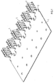
- Fig. 1 shows the bus bar 1, which has at one of its ends flat tabs 2 parallel to one another on which are connector plug sockets 3.
- this connector plug socket 3 is constituted of four pairs of elastic arms 4 placed next to one another and are held together by an applicator spring 5, the said applicator spring having a number of elastic arms equal to the number of interior elastic arms provided.
- the connector plug socket 3 is constituted of several elastic arms 4a (four in the present case), placed next to one another, which are formed in one piece onto the upper flat tab 2a of the upper layer of the bus bar 1. Opposite are placed four elastic arms 4b formed in one piece onto the lower flat tab 2b of the lower layer 1b of the bus bar 1. The lower flat tab 2b can then be fixed to the upper flat tab 2a by means of a crimped component 6.
- the two layers 1a and 1b of the bus bar 1 can also be interconnected by means of a lug 13 fixed on the lower layer 1b and engage in a notch 14 made in the upper layer 1a.
- the elastic arms 4a and 4b extend from a bottom plate 7 formed by the two flat tabs 2a and 2b, inclined towards one another, observing the direction opposite to the direction of the plugging of a blade contact (not shown) and continuing in the form of a funnel on the level of their upper end.
- the ends of the elastic arms 4a and 4b are brought together by the pressure of the applicator spring 5, ensuring a more secure contact of a blade contact (not shown) with the pair of elastic arms 4.
- Fig. 3 shows the components of the bus bar according to the invention.
- the bus bar 1 consists of the upper layer 1a, with flat tabs 2a, from which the elastic arms 4a extend almost vertically with respect to the layer 1a.
- This layer 1a is placed on the layer 1b, which, in turn, has flat tabs 2b with the elastic arms 4b.
- the two layers 1a and 1b of the bus bar 1 are at present fixed together pressing the applicator spring 5 to the elastic arms 4. It is thus possible to secure a very simple process of manufacture of the bus bar according to the invention. It is not absolutely necessary to envisage welding or brasing of the two layers 1a and 1b, nor the applicator of joining rivets.
- Fig. 4 shows a second form of embodiment according to the invention of the bus bar 1.
- This form of embodiment differs from the form of embodiment shown in Fig. 1 and 3, by reason of the fact that the two layers 1a and 1b are interconnected by means of an adhesive plate 8, which is usually non-conducting.
- the bus bar is therefore at the same potential, due to the fact that the applicator spring 5, which usually is electrically conducting, is in contact with the two contact arms 4a and 4b.
- the applicator spring 5, which comprises a connection plate 9 is connected by means of lugs 10 to the connector plug socket, which consists of the pair of elastic arms 4a and 4b. It is moreover possible to make an electricity-conducting connection by the openings 11 provided in the bus bar 1, openings into which it is possible to insert rivets. These openings 11 can also be used to fix the bus bar into a housing.
- Fig. 5 again shows the different components of the bus bar according to the second form of embodiment of the invention, the sticky adhesive plate being, as shown, placed between the two layers 1a and 1b of the bus bar 1.
- the adhesive plate 8 also has, at its front end, flat tabs 12, which place themselves between the flat tabs 2a and 2b
- a bus bar is obtained, the process of manufacture of which is simple, making it possible to pass strong currents and where heating up caused by the passage of high intensity current is minimised.
- the number of connector plug sockets can be increased, owing to the fact that the spacing between the connector plug sockets 3 can be smaller than when the contact bars are made in one layer.
- the bus bar is usually made by the process of die stamping from a steel sheet blank, the elastic arms 4a and 4b being folded back laterally and upward.
Landscapes
- Connections Effected By Soldering, Adhesion, Or Permanent Deformation (AREA)
- Installation Of Bus-Bars (AREA)
- Connection Or Junction Boxes (AREA)
Applications Claiming Priority (2)
| Application Number | Priority Date | Filing Date | Title |
|---|---|---|---|
| FR0110674A FR2828590B1 (fr) | 2001-08-08 | 2001-08-08 | Barre de bus |
| FR0110674 | 2001-08-08 |
Publications (1)
| Publication Number | Publication Date |
|---|---|
| EP1283577A1 true EP1283577A1 (de) | 2003-02-12 |
Family
ID=8866435
Family Applications (1)
| Application Number | Title | Priority Date | Filing Date |
|---|---|---|---|
| EP02017639A Withdrawn EP1283577A1 (de) | 2001-08-08 | 2002-08-06 | Sammelschiene |
Country Status (3)
| Country | Link |
|---|---|
| US (1) | US6722926B2 (de) |
| EP (1) | EP1283577A1 (de) |
| FR (1) | FR2828590B1 (de) |
Cited By (3)
| Publication number | Priority date | Publication date | Assignee | Title |
|---|---|---|---|---|
| CN102217142A (zh) * | 2008-11-17 | 2011-10-12 | Jst公司 | 母端子组件 |
| CN104347994A (zh) * | 2013-08-01 | 2015-02-11 | 李尔公司 | 电端子组件 |
| DE202018100959U1 (de) * | 2018-02-21 | 2019-05-23 | Weidmüller Interface GmbH & Co. KG | Kontakt- und Busschienenanordnung |
Families Citing this family (43)
| Publication number | Priority date | Publication date | Assignee | Title |
|---|---|---|---|---|
| US7789756B2 (en) * | 2002-09-13 | 2010-09-07 | Igt | Wagering gaming device having simulated control of movement of game functional elements |
| US7326115B2 (en) * | 2004-08-20 | 2008-02-05 | Igt | Gaming device and method having a first interactive game which determines a function of a second wagering game |
| US7931531B2 (en) * | 2006-11-08 | 2011-04-26 | Igt | Gaming system and method providing an interactive game with automatic wagers |
| WO2008076813A2 (en) | 2006-12-13 | 2008-06-26 | Panduit Corp. | Communication jack having layered plug interface contacts |
| JP4428406B2 (ja) * | 2007-06-18 | 2010-03-10 | 株式会社デンソー | Uターンバスバー |
| US7764498B2 (en) * | 2007-09-24 | 2010-07-27 | Sixis, Inc. | Comb-shaped power bus bar assembly structure having integrated capacitors |
| US20090104964A1 (en) * | 2007-10-17 | 2009-04-23 | Igt | Gaming system, gaming device and gaming method providing player physical activation of the symbol generator |
| US8231448B2 (en) * | 2007-11-09 | 2012-07-31 | Igt | Gaming system and method for providing purchasable bonus opportunities |
| DE102008009357A1 (de) * | 2008-02-14 | 2009-08-27 | Phoenix Contact Gmbh & Co. Kg | Elektrische Anschlusseinrichtung |
| CN201303102Y (zh) * | 2008-09-09 | 2009-09-02 | 富士康(昆山)电脑接插件有限公司 | 电连接器及电连接器组件 |
| US8702455B1 (en) * | 2010-02-10 | 2014-04-22 | The Durham Company | Connector assemblies and blade contact structures therefor |
| JP5845029B2 (ja) * | 2011-09-16 | 2016-01-20 | 日本航空電子工業株式会社 | ハウジングレスコネクタ |
| US8939787B2 (en) * | 2012-08-27 | 2015-01-27 | Schneider Electric USA, Inc. | Dual material ground clip for a busway plug in unit |
| JP6082547B2 (ja) * | 2012-09-04 | 2017-02-15 | 株式会社アテックス | バスバーインサート樹脂成形品の製造方法 |
| US8986030B2 (en) | 2012-12-06 | 2015-03-24 | Phoenix Contact Development and Manufacturing, Inc. | Modular electric power distribution system |
| DE202013103444U1 (de) * | 2013-07-31 | 2014-11-04 | Weidmüller Interface GmbH & Co. KG | Kontaktelement für eine Steckanordnung eines insbesondere außen geführten Bussystems |
| US9190756B2 (en) | 2013-08-01 | 2015-11-17 | Lear Corporation | Electrical terminal assembly |
| US9502782B2 (en) * | 2013-10-09 | 2016-11-22 | Rockwell Automation Technologies, Inc. | System and method for transmitting power through a plug-in unit |
| US9711926B2 (en) | 2013-11-19 | 2017-07-18 | Lear Corporation | Method of forming an interface for an electrical terminal |
| US9331448B2 (en) * | 2014-03-25 | 2016-05-03 | Tyco Electronics Corporation | Electrical connector having primary and secondary leadframes |
| US9166309B1 (en) * | 2014-06-27 | 2015-10-20 | Tyco Electronics Corporation | Bus bar with connector shroud |
| US10566708B2 (en) * | 2015-12-01 | 2020-02-18 | Quickwire Limited | Electrical connector |
| DE102016108069A1 (de) * | 2016-05-02 | 2017-11-02 | Valeo Systèmes d'Essuyage | Kontaktelement zur Ausbildung einer elektrischen Verbindung mit einem Gegenelement, elektrische Verbindung und Scheibenwischermotor |
| US10763607B2 (en) | 2016-08-22 | 2020-09-01 | Interplex Industries, Inc. | Electrical connector |
| US10522945B2 (en) | 2016-08-22 | 2019-12-31 | Interplex Industries, Inc. | Electrical connector |
| US9905953B1 (en) | 2016-09-30 | 2018-02-27 | Slobodan Pavlovic | High power spring-actuated electrical connector |
| DE102017001166A1 (de) * | 2017-01-31 | 2018-08-02 | Kostal Kontakt Systeme Gmbh | Kontaktlamelle für ein buchsenartiges Steckverbinderteil und buchsenartiges Steckverbinderteil |
| CN111937250B (zh) | 2018-02-26 | 2022-09-30 | 皇家精密制品有限责任公司 | 用于高功率应用的弹簧致动式电连接器 |
| WO2019237009A1 (en) | 2018-06-07 | 2019-12-12 | Royal Precision Products, Llc | Electrical connector system with internal spring component |
| US10622771B2 (en) * | 2018-09-07 | 2020-04-14 | Hamilton Sundstrand Corporation | Power modules for power distribution assemblies |
| WO2020150399A1 (en) | 2019-01-15 | 2020-07-23 | Royal Precision Products, Llc | Shielded electrical connector system with internal spring component |
| DE112020000459T5 (de) | 2019-01-21 | 2021-11-25 | Royal Precision Products, Llc | Stromverteilungsanordnung mit schraubenlosem sammelschienensystem |
| US11721942B2 (en) | 2019-09-09 | 2023-08-08 | Eaton Intelligent Power Limited | Connector system for a component in a power management system in a motor vehicle |
| WO2021050607A1 (en) | 2019-09-09 | 2021-03-18 | Royal Precision Products Llc | Electrical busbar and method of fabricating the same |
| CN114787815A (zh) | 2019-09-09 | 2022-07-22 | 伊顿智能动力有限公司 | 具有可读和可记录标记的连接器记录系统 |
| JP7314012B2 (ja) * | 2019-10-07 | 2023-07-25 | 日本航空電子工業株式会社 | ソケットコンタクト及びコネクタ |
| US11069999B2 (en) * | 2019-12-20 | 2021-07-20 | Lear Corporation | Electrical terminal assembly with connection retainer |
| US10992073B1 (en) * | 2019-12-20 | 2021-04-27 | Lear Corporation | Electrical terminal assembly with increased contact area |
| CN111180928A (zh) * | 2020-02-13 | 2020-05-19 | 苏州远野汽车技术有限公司 | 一种双向对插接触式端子 |
| DE112021003695T5 (de) | 2020-07-29 | 2023-06-29 | Eaton Intelligent Power Limited | Verbindersystem einschliesslich eines verriegelungssystems |
| WO2023283151A1 (en) * | 2021-07-06 | 2023-01-12 | Interplex Industries, Inc. | Electrical coupler |
| JP2024527600A (ja) * | 2021-07-16 | 2024-07-25 | イートン インテリジェント パワー リミテッド | 配電システムで使用するためのコネクタシステム |
| US12136500B2 (en) | 2021-08-18 | 2024-11-05 | Eaton Intelligent Power Limited | Electrical busbar and method of fabricating the same |
Citations (3)
| Publication number | Priority date | Publication date | Assignee | Title |
|---|---|---|---|---|
| DE3335047A1 (de) * | 1983-09-28 | 1985-04-11 | Felten & Guilleaume Energietechnik GmbH, 5000 Köln | Verfahren zur herstellung eines nh-lyrakontakts |
| EP0814551A1 (de) * | 1996-06-19 | 1997-12-29 | Framatome Connectors International | Kontaktschiene mit Buchsenleisten und steckbare Baugruppe mit solcher Kontaktschiene |
| EP0872922A2 (de) * | 1997-04-18 | 1998-10-21 | ABB SACE S.p.A. | Elektronische Energieverteilungsvorrichtung |
Family Cites Families (2)
| Publication number | Priority date | Publication date | Assignee | Title |
|---|---|---|---|---|
| US3880494A (en) * | 1974-04-25 | 1975-04-29 | Square D Co | Socket base assembly |
| DE2841234A1 (de) * | 1978-09-22 | 1980-04-03 | Fischer Artur Dr H C | Kontaktleiste als teil eines experimentierbaukastens |
-
2001
- 2001-08-08 FR FR0110674A patent/FR2828590B1/fr not_active Expired - Fee Related
-
2002
- 2002-08-05 US US10/212,552 patent/US6722926B2/en not_active Expired - Fee Related
- 2002-08-06 EP EP02017639A patent/EP1283577A1/de not_active Withdrawn
Patent Citations (3)
| Publication number | Priority date | Publication date | Assignee | Title |
|---|---|---|---|---|
| DE3335047A1 (de) * | 1983-09-28 | 1985-04-11 | Felten & Guilleaume Energietechnik GmbH, 5000 Köln | Verfahren zur herstellung eines nh-lyrakontakts |
| EP0814551A1 (de) * | 1996-06-19 | 1997-12-29 | Framatome Connectors International | Kontaktschiene mit Buchsenleisten und steckbare Baugruppe mit solcher Kontaktschiene |
| EP0872922A2 (de) * | 1997-04-18 | 1998-10-21 | ABB SACE S.p.A. | Elektronische Energieverteilungsvorrichtung |
Cited By (3)
| Publication number | Priority date | Publication date | Assignee | Title |
|---|---|---|---|---|
| CN102217142A (zh) * | 2008-11-17 | 2011-10-12 | Jst公司 | 母端子组件 |
| CN104347994A (zh) * | 2013-08-01 | 2015-02-11 | 李尔公司 | 电端子组件 |
| DE202018100959U1 (de) * | 2018-02-21 | 2019-05-23 | Weidmüller Interface GmbH & Co. KG | Kontakt- und Busschienenanordnung |
Also Published As
| Publication number | Publication date |
|---|---|
| US20030032338A1 (en) | 2003-02-13 |
| FR2828590B1 (fr) | 2003-09-26 |
| US6722926B2 (en) | 2004-04-20 |
| FR2828590A1 (fr) | 2003-02-14 |
Similar Documents
| Publication | Publication Date | Title |
|---|---|---|
| US6722926B2 (en) | Bus bar | |
| EP0419031B1 (de) | Elektrischer Anzapfstecker | |
| US8986030B2 (en) | Modular electric power distribution system | |
| CA2006170C (en) | Clamp type connection device | |
| CN112219322A (zh) | 高电流插接连接器及其装配方法 | |
| JPH02199779A (ja) | 電気コネクタ | |
| US20030022536A1 (en) | Electrical connection box and method for producing it | |
| JP4096431B2 (ja) | 多連ヒューズ素子および該多連ヒューズ素子を用いた多連ヒューズ | |
| US20130137305A1 (en) | Connector | |
| CN121840230A (zh) | 导电端子和电连接器 | |
| JPH0799793B2 (ja) | 自動車用の電気装置 | |
| CN106068571B (zh) | 在电池系统的两个电池模块之间的连接系统 | |
| CN106170894B (zh) | 接线盒 | |
| CN110176677A (zh) | 触点及总线布置系统 | |
| US5281172A (en) | Electrical outlet adapter | |
| US6524113B1 (en) | Automobile junction box with replaceable busbar circuit blocks | |
| US20190312391A1 (en) | Plug Connector Module Having Spring Links | |
| CN117223176B (zh) | 插头连接器组件和插头连接件 | |
| EP0929127A1 (de) | Steckverbindergehäuse | |
| CN110176678B (zh) | 触点及总线布置系统、电子器件壳体系统和拆除电子器件壳体的方法 | |
| GB2424130A (en) | Planar electrical terminal | |
| JP7650960B2 (ja) | 分配器ブロック及び分配器ブロックを生産するための方法 | |
| JP2000209739A (ja) | 電気接続箱のバスバ―回路構造 | |
| US4948380A (en) | Dual contact electrical terminal | |
| US20030057074A1 (en) | Contact arrangement for a grounding switch in switchgears which are provided for supplying and distributing power |
Legal Events
| Date | Code | Title | Description |
|---|---|---|---|
| PUAI | Public reference made under article 153(3) epc to a published international application that has entered the european phase |
Free format text: ORIGINAL CODE: 0009012 |
|
| AK | Designated contracting states |
Designated state(s): AT BE BG CH CY CZ DE DK EE ES FI FR GB GR IE IT LI LU MC NL PT SE SK TR |
|
| AX | Request for extension of the european patent |
Extension state: AL LT LV MK RO SI |
|
| 17P | Request for examination filed |
Effective date: 20030730 |
|
| AKX | Designation fees paid |
Designated state(s): DE FR GB |
|
| RAP1 | Party data changed (applicant data changed or rights of an application transferred) |
Owner name: FCI |
|
| STAA | Information on the status of an ep patent application or granted ep patent |
Free format text: STATUS: THE APPLICATION IS DEEMED TO BE WITHDRAWN |
|
| 18D | Application deemed to be withdrawn |
Effective date: 20090303 |