EP1283584A2 - Stator d'un générateur à courant alternatif à dents evasés - Google Patents
Stator d'un générateur à courant alternatif à dents evasés Download PDFInfo
- Publication number
- EP1283584A2 EP1283584A2 EP02077897A EP02077897A EP1283584A2 EP 1283584 A2 EP1283584 A2 EP 1283584A2 EP 02077897 A EP02077897 A EP 02077897A EP 02077897 A EP02077897 A EP 02077897A EP 1283584 A2 EP1283584 A2 EP 1283584A2
- Authority
- EP
- European Patent Office
- Prior art keywords
- slot
- stator
- width
- stator assembly
- legs
- Prior art date
- Legal status (The legal status is an assumption and is not a legal conclusion. Google has not performed a legal analysis and makes no representation as to the accuracy of the status listed.)
- Withdrawn
Links
Images

Classifications
-
- H—ELECTRICITY
- H02—GENERATION; CONVERSION OR DISTRIBUTION OF ELECTRIC POWER
- H02K—DYNAMO-ELECTRIC MACHINES
- H02K15/00—Processes or apparatus specially adapted for manufacturing, assembling, maintaining or repairing of dynamo-electric machines
- H02K15/13—Applying slot closure means in the cores; Manufacture of slot closure means
-
- Y—GENERAL TAGGING OF NEW TECHNOLOGICAL DEVELOPMENTS; GENERAL TAGGING OF CROSS-SECTIONAL TECHNOLOGIES SPANNING OVER SEVERAL SECTIONS OF THE IPC; TECHNICAL SUBJECTS COVERED BY FORMER USPC CROSS-REFERENCE ART COLLECTIONS [XRACs] AND DIGESTS
- Y10—TECHNICAL SUBJECTS COVERED BY FORMER USPC
- Y10T—TECHNICAL SUBJECTS COVERED BY FORMER US CLASSIFICATION
- Y10T29/00—Metal working
- Y10T29/49—Method of mechanical manufacture
- Y10T29/49002—Electrical device making
- Y10T29/49009—Dynamoelectric machine
-
- Y—GENERAL TAGGING OF NEW TECHNOLOGICAL DEVELOPMENTS; GENERAL TAGGING OF CROSS-SECTIONAL TECHNOLOGIES SPANNING OVER SEVERAL SECTIONS OF THE IPC; TECHNICAL SUBJECTS COVERED BY FORMER USPC CROSS-REFERENCE ART COLLECTIONS [XRACs] AND DIGESTS
- Y10—TECHNICAL SUBJECTS COVERED BY FORMER USPC
- Y10T—TECHNICAL SUBJECTS COVERED BY FORMER US CLASSIFICATION
- Y10T29/00—Metal working
- Y10T29/49—Method of mechanical manufacture
- Y10T29/49002—Electrical device making
- Y10T29/49009—Dynamoelectric machine
- Y10T29/49012—Rotor
-
- Y—GENERAL TAGGING OF NEW TECHNOLOGICAL DEVELOPMENTS; GENERAL TAGGING OF CROSS-SECTIONAL TECHNOLOGIES SPANNING OVER SEVERAL SECTIONS OF THE IPC; TECHNICAL SUBJECTS COVERED BY FORMER USPC CROSS-REFERENCE ART COLLECTIONS [XRACs] AND DIGESTS
- Y10—TECHNICAL SUBJECTS COVERED BY FORMER USPC
- Y10T—TECHNICAL SUBJECTS COVERED BY FORMER US CLASSIFICATION
- Y10T29/00—Metal working
- Y10T29/49—Method of mechanical manufacture
- Y10T29/49002—Electrical device making
- Y10T29/4902—Electromagnet, transformer or inductor
- Y10T29/49071—Electromagnet, transformer or inductor by winding or coiling
-
- Y—GENERAL TAGGING OF NEW TECHNOLOGICAL DEVELOPMENTS; GENERAL TAGGING OF CROSS-SECTIONAL TECHNOLOGIES SPANNING OVER SEVERAL SECTIONS OF THE IPC; TECHNICAL SUBJECTS COVERED BY FORMER USPC CROSS-REFERENCE ART COLLECTIONS [XRACs] AND DIGESTS
- Y10—TECHNICAL SUBJECTS COVERED BY FORMER USPC
- Y10T—TECHNICAL SUBJECTS COVERED BY FORMER US CLASSIFICATION
- Y10T29/00—Metal working
- Y10T29/53—Means to assemble or disassemble
- Y10T29/5313—Means to assemble electrical device
- Y10T29/53143—Motor or generator
Definitions
- the present invention relates to a stator core of a dynamoelectric machine.
- a generator typically includes a stator assembly comprising a stator core and a stator winding, and a rotor.
- U.S. Patent No. 3,953,753 issued to Barrett entitled “THREE PHASE ALTERNATORS” disclose a three phase alternator suited for automotive use having an annular magnetic stator core having a plurality of stator poles projecting therefrom, and separated from each other by a corresponding plurality of stator slots.
- Each slot has an open bottom formed by tooth tips of adjacent stator teeth.
- the slot opening is relatively narrow, compared with a width of the slot itself, as is conventional, so as to provide both a magnetic flux path and provide for wire retention.
- the relatively narrow slot opening formed by the tooth tips which are typically stamped directly into a steel lamination into the desired profile, restricts entry of the stator windings. Accordingly, obtaining an increasingly higher stator slot fill (i.e. , the percentage of copper wire total cross-sectional area to available cross-sectional area) is difficult to achieve.
- One object of the present invention is to provide a stator core for a dynamoelectric machine such as an alternating current (AC) generator that solves one or more of the problems set forth above.
- the present invention provides a slot opening that is increased relative to conventional slot openings ( i.e. , when compared to the width of the slot itself).
- the increased size slot openings allow stator windings to be more easily inserted into the slots, and further, provides for an increased slot fill. Thereafter, the slot opening is closed up in order to provide a magnetic flux path and further to provide for wire retention. This is accomplished by cold-forming the ends of the stator teeth after the core itself has been made and wound with the stator winding to form "tooth tips.”
- a stator assembly for a dynamoelectric machine which includes a stator core having a yoke, a plurality of teeth separated by intervening slots.
- the stator core extends along a longitudinal axis.
- a radially innermost portion of at least one of the teeth includes a pair of legs with a recess located therebetween. The arrangement of the legs and the recess facilitates the cold-working of the stator teeth to form the tooth tips.
- a method of making a stator assembly according to the invention is also presented.
- Figure 1 is a partial, plan view of a stator core according to the present invention.
- Figure 2 is an enlarged view of a pair of adjacent stator teeth corresponding to the encircled portion shown in Figure 1.
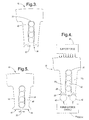
- Figures 3-5 are simplified, plan views of a pair of adjacent stator teeth illustrating the progression of the tooth tip forming method according to the invention.
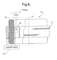
- Figure 6 is a diagrammatic view of a stator assembly, with portions broken away and sectioned, showing a cold-forming operation according to the invention.
- FIG. 1 is a partial plan view of a stator core 10 in accordance with the present invention.
- Core 10 includes a yoke 12, a plurality of teeth 14, and a plurality of intervening slots 16. Each slot 16 has a nominal slot width 17, and a slot opening having a width 18.
- the stator core 10 shown in Figure 1 is that produced after a first stage of manufacturing, but prior to insertion of stator windings, and a cold-forming operation to form tooth tips to be described in detail hereinafter.
- Stator core 10 is generally cylindrical having a main longitudinal axis "A" (best shown in Figure 6), which may be described as extending into the paper of Figure 1 at center point 19.
- Stator core 10 has an outside diameter of radius R, as shown.
- the relative radial length in Figure 1 has been foreshortened in relative scale for clarity of illustration purposes only.
- Core 10 is suitable for use in a stator assembly for a dynamoelectric machine, such as an AC generator for an automotive vehicle.
- a plurality of relatively thin, generally circular laminations are stamped or otherwise formed from suitable magnetic material (e.g. , silicon steel or the like), and are then adhered together in a stack having a predesired axial length, as understood generally by one of ordinary skill in the art.
- FIG. 2 is an enlarged view of the portion of Figure 1 encircled in phantom line.
- Each slot 16 is formed by adjacent teeth, shown in Figure 2 as adjacent teeth 14 1 and 14 2 .
- Slot 16 is configured to receive stator windings, as known in the art.
- Slot 16 includes a top 20 adjacent to yoke 12 and a pair of sides 22 and 24 defined by adjacent teeth 14 1 and 14 2 (in addition to an open bottom defining slot opening 18 described in connection with Figure 1).
- sides 22 and 24 are generally parallel over the radial extent of teeth 14 1 and 14 2 .
- Tooth 14 in the illustrated embodiment, circumscribes a predetermined angle 21 taken relative to center point 19 (best shown in Figure 1). In one embodiment, 21 is approximately 5 degrees, forming a 72-tooth, 72-slot, stator core 10.
- the slot opening 18 is greater than about 75 percent of the slot width 17, more preferably greater than about 80 percent, and in a constructed embodiment, is approximately 83 percent ( i.e. , a slot opening of 0.1005 inches/a slot width of 0.1205 inches).
- the increased slot opening is achieved by producing ( e.g. , stamping) the profile shown in Figure 1, and deferring formation of the tooth tips until after the core 10 itself has been made and wound with stator windings.
- stamping the profile shown in Figure 1
- a variety of features initially are formed on a radially innermost portion of the plurality of teeth 14 (first tips 26).
- each tooth 14 includes (i) a pair of legs 28; (ii) a recess 32 disposed therebetween, and (iii) a pair of relief radii 34 and 36.
- Recess 32 is formed, in part, by the inner sides of legs 28 and 30.
- the inner sides form a predefined angle 22 relative to each other.
- the predefined angle 22 may be at least about 45 degrees, more preferably at least about 60 degrees, and may be about 66 degrees in a constructed embodiment ( e.g. , 66.1552 degrees).
- the recess 32 has a radial extent that is at least one-half of the radial extent 37 of legs 28 and 30, and, more preferably, approximately the same radial extent as legs 28 and 30.
- Figures 3-5 show the progression of a method of manufacturing stator core 10 according to the invention.
- Figure 3 shows a first stage, where stator core 10 has a stator slot liner (insulator) 38 disposed in slot 16, and where stator windings 40 (e.g. , copper magnet wire) have been inserted in the liner 38.
- stator slot liner can be omitted and a powder coat of insulating material can be used in lieu thereof.
- Figure 4 shows the next stage, particularly, the beginning of a cold-forming operation on the radially innermost ends of teeth 14 1 and 14 2 to form final tooth tips.
- Figure 4 shows a suitably configured forming tool (e.g. , a suitably sized ball arranged in a ball roller configuration 42). Ball roller 42 is shown disposed against legs 28 and 30 of teeth 14.
- Figure 4 also shows the radial forces, designated 44 RADIAL that are applied during the cold-forming operation.
- a support force, designated support force 46 is employed such as by providing a reaction surface or in other known ways.
- the ball roller 42 is rolled along the bottom of tooth 14 (i.e. , the inside diameter of the stator core 10) in an axial direction. This movement deforms the material at the bottom ( i.e. , radially innermost) of tooth 14 to define a final tooth tip 48.
- Figure 5 illustrates the final or completed stage where the tooth tip 48 is newly formed on a radially innermost portion of each tooth 14.
- a second slot opening width 50 is established that is smaller than the first slot opening width 18 shown in Figure 1.
- the closed up slot width provides a magnetic flux path, and further functions to retain the stator windings 40.
- Figure 6 is a simplified view of a stator assembly 52 that includes a stator core 10, with portions broken away and sectioned.
- Figure 6 shows an axial force, designated 44 AXIAL that is applied by the ball roller 42 to the stator teeth 14.
- Figure 6 also shows longitudinal axis "A.”
- a first portion of core 10, designated first axial portion 54 is deformed using ball roller 42. This is done by commencing the forming operation at a first axial end of stator core 10 and proceeding in a first axial direction ( e.g. , in the down direction given the orientation of assembly 52 in Figure 6).
- the stator assembly 52 is then turned over, and the remaining axial portion, designated second axial portion 56, is worked.
- stator core 10 This is done by commencing the cold-forming operation at a second axial end of stator core 10 (the bottom end in Figure 6) and proceeding in a second axial direction opposite the first axial direction mentioned above (i.e. , in the up direction in Figure 6).
- the foregoing steps are performed so that forces from the ball roller 42 do not cause the individual laminations that form stator core 10 to separate at the bottom edge of the stack as the ball roller exits.
- an alternate tooth-end configuration yielding a wide slot opening is initially made (e.g. , stamped). Then the tooth tips are cold-formed on the radially-innermost ends of the stator teeth after the stator core itself has been manufactured and wound with magnet wire.
- the features of the invention allow the stator winding to be inserted through an increased-size slot opening compared to the slot openings found in conventional arrangements. The foregoing increase in size allows a larger size conductor to be inserted in the slot, thereby obtaining a higher stator slot fill, which allows and enables a higher generator efficiency and output for a given package size.
- the enlarged slot opening is closed up using, for example, a cold-forming operation.
- the closed up slot opening which is now reduced in width (akin to a conventional slot opening) provides a magnetic flux path, and further provides a wire retention function.
Landscapes
- Engineering & Computer Science (AREA)
- Manufacturing & Machinery (AREA)
- Power Engineering (AREA)
- Iron Core Of Rotating Electric Machines (AREA)
Applications Claiming Priority (2)
| Application Number | Priority Date | Filing Date | Title |
|---|---|---|---|
| US924802 | 2001-08-08 | ||
| US09/924,802 US6742238B2 (en) | 2001-08-08 | 2001-08-08 | Flare tooth stator for an AC generator |
Publications (2)
| Publication Number | Publication Date |
|---|---|
| EP1283584A2 true EP1283584A2 (fr) | 2003-02-12 |
| EP1283584A3 EP1283584A3 (fr) | 2004-09-22 |
Family
ID=25450753
Family Applications (1)
| Application Number | Title | Priority Date | Filing Date |
|---|---|---|---|
| EP02077897A Withdrawn EP1283584A3 (fr) | 2001-08-08 | 2002-07-17 | Stator d'un générateur à courant alternatif à dents evasés |
Country Status (2)
| Country | Link |
|---|---|
| US (2) | US6742238B2 (fr) |
| EP (1) | EP1283584A3 (fr) |
Cited By (1)
| Publication number | Priority date | Publication date | Assignee | Title |
|---|---|---|---|---|
| CN112039298A (zh) * | 2020-08-03 | 2020-12-04 | 安徽巨一科技股份有限公司 | 一种扁线电机定子端部扭头的装置及方法 |
Families Citing this family (25)
| Publication number | Priority date | Publication date | Assignee | Title |
|---|---|---|---|---|
| JP2000134852A (ja) * | 1998-10-28 | 2000-05-12 | Mitsubishi Electric Corp | 車両用交流発電機の固定子とその製造方法 |
| US6742238B2 (en) * | 2001-08-08 | 2004-06-01 | Delphi Technologies, Inc. | Flare tooth stator for an AC generator |
| US7170211B2 (en) * | 2002-01-24 | 2007-01-30 | Visteon Global Technologies, Inc. | Stator winding having transitions |
| US7129612B2 (en) * | 2002-01-24 | 2006-10-31 | Visteon Global Technologies, Inc. | Stator assembly with cascaded winding and method of making same |
| US6949857B2 (en) * | 2003-03-14 | 2005-09-27 | Visteon Global Technologies, Inc. | Stator of a rotary electric machine having stacked core teeth |
| US7081697B2 (en) * | 2004-06-16 | 2006-07-25 | Visteon Global Technologies, Inc. | Dynamoelectric machine stator core with mini caps |
| US7386931B2 (en) | 2004-07-21 | 2008-06-17 | Visteon Global Technologies, Inc. | Method of forming cascaded stator winding |
| US7269888B2 (en) * | 2004-08-10 | 2007-09-18 | Visteon Global Technologies, Inc. | Method of making cascaded multilayer stator winding with interleaved transitions |
| US20060197398A1 (en) * | 2005-03-07 | 2006-09-07 | Valeo Electrical Systems, Inc. | Composite winding |
| JP4333641B2 (ja) * | 2005-06-16 | 2009-09-16 | 株式会社デンソー | 回転電機の固定子製造方法 |
| US20080164773A1 (en) * | 2007-01-06 | 2008-07-10 | Chih-Yu Wang | Stator for a Liquid Cooling Type Direct Drive Motor |
| JP2011036010A (ja) * | 2009-07-31 | 2011-02-17 | Hitachi Ltd | 回転電機 |
| JP5537964B2 (ja) * | 2010-01-19 | 2014-07-02 | 株式会社日立製作所 | 回転電機 |
| US8789259B2 (en) * | 2011-11-17 | 2014-07-29 | Remy Technologies, L.L.C. | Method of winding a stator core with a continuous conductor having a rectangular cross-section and a stator core |
| US9467010B2 (en) | 2011-11-17 | 2016-10-11 | Remy Technologies, L.L.C. | Method of winding a stator core with a continuous conductor having a rectangular cross-section and a stator core |
| BR102012022079A2 (pt) * | 2012-08-31 | 2014-09-16 | Whirlpool Sa | Processo de confecção de estator de máquina dínamo-elétrica e sistema de calibração de estator de máquina dínamo-elétrica |
| BR102012022080A2 (pt) * | 2012-08-31 | 2014-06-17 | Whirlpool Sa | Processo de confecção de estator de máquina dínamo-elétrica e sistema de deformação de estator de máquina dínamo-elétrica |
| TWI517528B (zh) * | 2014-07-01 | 2016-01-11 | Victory Ind Corp | 製造交流發電機定子繞組的方法 |
| TWI517524B (zh) | 2014-07-01 | 2016-01-11 | 勝利工業股份有限公司 | 交流發電機定子及定子繞組 |
| TWI517530B (zh) | 2014-07-01 | 2016-01-11 | Victory Ind Corp | Alternator stator windings and stator windings |
| DE202016102217U1 (de) * | 2015-05-08 | 2016-07-22 | Johnson Electric S.A. | Einphasiger Außenläufermotor und Ständer desselben |
| CN107040057A (zh) * | 2016-02-03 | 2017-08-11 | 德昌电机(深圳)有限公司 | 风机 |
| CN111384790A (zh) * | 2018-12-28 | 2020-07-07 | 福特全球技术公司 | 用于电机的定子及电机 |
| JP2022055707A (ja) * | 2020-09-29 | 2022-04-08 | 本田技研工業株式会社 | 回転電機 |
| DE102021112931A1 (de) * | 2021-05-19 | 2022-11-24 | Dr. Ing. H.C. F. Porsche Aktiengesellschaft | Stator einer elektrischen Maschine, Verfahren zum Herstellen desselben und elektrische Maschine |
Family Cites Families (22)
| Publication number | Priority date | Publication date | Assignee | Title |
|---|---|---|---|---|
| US92152A (en) * | 1869-07-06 | Improvement in knob-latches | ||
| US2407935A (en) | 1944-05-25 | 1946-09-17 | Chrysler Corp | Electrical machine |
| GB861889A (en) * | 1958-09-29 | 1961-03-01 | Lucas Industries Ltd | Rotor or stator constructions for dynamo-electric machines |
| CH546501A (de) | 1972-06-20 | 1974-02-28 | Bbc Brown Boveri & Cie | Verfahren zur herstellung von stableitern fuer die statorwicklung einer rotierenden elektrischen hochspannungsmaschine. |
| US3953753A (en) | 1975-01-20 | 1976-04-27 | Barrett Edward L | Three phase alternators |
| DE2629532A1 (de) * | 1975-07-03 | 1977-01-27 | Sev Alternateurs | Verfahren und vorrichtung fuer einen stator oder rotor einer elektrischen rotationsmaschine |
| JPS529805A (en) * | 1975-07-11 | 1977-01-25 | Nippon Denso Co Ltd | Manufacturing method of armature for small rotary machine |
| US4176444A (en) * | 1977-09-19 | 1979-12-04 | Industra Products, Inc. | Method and apparatus for assembling dynamoelectric machine stators |
| DE2848618A1 (de) * | 1978-11-09 | 1980-05-22 | Bosch Gmbh Robert | Elektrische maschine und verfahren zu ihrer herstellung |
| US4613780A (en) | 1984-10-12 | 1986-09-23 | General Electric Company | Lanced strip and edgewise wound core |
| JPH063979B2 (ja) * | 1986-03-03 | 1994-01-12 | 株式会社日立製作所 | 回転機の電機子及びその製造方法 |
| JPH03284147A (ja) | 1990-03-28 | 1991-12-13 | Mitsubishi Electric Corp | 車両用交流発電機 |
| JP2827773B2 (ja) | 1992-12-21 | 1998-11-25 | 株式会社日立製作所 | 回転電機子と電機子巻線の成形方法 |
| US5739617A (en) * | 1994-12-14 | 1998-04-14 | Nippondenso Co., Ltd. | Rotary electric machine |
| US5806169A (en) * | 1995-04-03 | 1998-09-15 | Trago; Bradley A. | Method of fabricating an injected molded motor assembly |
| US6137201A (en) * | 1997-05-26 | 2000-10-24 | Denso Corporation | AC generator for vehicles |
| JPH11252832A (ja) * | 1998-03-06 | 1999-09-17 | Asmo Co Ltd | コア・シート、コアおよび電機子の製造方法 |
| JP3537321B2 (ja) * | 1998-08-17 | 2004-06-14 | 株式会社東芝 | モータのモールドコア |
| EP1109299B9 (fr) * | 1999-12-14 | 2005-06-15 | Mitsubishi Denki Kabushiki Kaisha | Procédé de fabrication d'un alternateur |
| US6687974B1 (en) * | 1999-12-27 | 2004-02-10 | Mitsubishi Denki Kabushiki Kaisha | Method for manufacturing an alternator |
| US6278213B1 (en) * | 2000-01-13 | 2001-08-21 | Delphi Technologies, Inc. | High fill stator design |
| US6742238B2 (en) * | 2001-08-08 | 2004-06-01 | Delphi Technologies, Inc. | Flare tooth stator for an AC generator |
-
2001
- 2001-08-08 US US09/924,802 patent/US6742238B2/en not_active Expired - Fee Related
-
2002
- 2002-07-17 EP EP02077897A patent/EP1283584A3/fr not_active Withdrawn
-
2004
- 2004-05-04 US US10/838,688 patent/US20040207285A1/en not_active Abandoned
Cited By (1)
| Publication number | Priority date | Publication date | Assignee | Title |
|---|---|---|---|---|
| CN112039298A (zh) * | 2020-08-03 | 2020-12-04 | 安徽巨一科技股份有限公司 | 一种扁线电机定子端部扭头的装置及方法 |
Also Published As
| Publication number | Publication date |
|---|---|
| EP1283584A3 (fr) | 2004-09-22 |
| US20030030350A1 (en) | 2003-02-13 |
| US20040207285A1 (en) | 2004-10-21 |
| US6742238B2 (en) | 2004-06-01 |
Similar Documents
| Publication | Publication Date | Title |
|---|---|---|
| US6742238B2 (en) | Flare tooth stator for an AC generator | |
| US20030033709A1 (en) | High slot-fill stator | |
| US7468570B2 (en) | Stator assembly for an electric machine and method of manufacturing the same | |
| US6313559B1 (en) | Stator arrangement of rotary electric machine | |
| JP3561249B2 (ja) | 交流発電機の固定子およびその製造方法 | |
| EP1146624B1 (fr) | Noyau statorique de machine rotative pour véhicule et son procédé de fabrication | |
| US6935012B2 (en) | Dynamo electric machine and method of manufacturing the same | |
| US6317962B1 (en) | Method for producing a stator of an alternating-current dynamo-electric machine | |
| US6703750B2 (en) | Stator of rotary electric machine and method for making the same | |
| US20160254718A1 (en) | Segment conductors, stator, rotating electrical machine, and vehicle and method of manufacturing the segment conductors | |
| US20040187293A1 (en) | Radial insertion of stator hairpin windings | |
| EP0695019A1 (fr) | Rotor pour machine électrique, en particulier pour moteur électrique destiné à faire démarrer le moteur à combustion interne d'un véhicule automobile et procédé pour sa fabrication | |
| US20040207284A1 (en) | Stator assembly including a core slot insert member | |
| JPH048149A (ja) | ステータの製造方法 | |
| EP0235597A2 (fr) | Armature pour une machine électrique rotative et méthode de sa fabrication | |
| US20020093269A1 (en) | Slot area undercut for segmented stators | |
| CN106663976B (zh) | 定子组装方法以及定子 | |
| US20050046299A1 (en) | Windings for electric machines | |
| US7726005B2 (en) | Method for making an electromagnetically excitable core of an electrical machine with a multiphase winding | |
| CN118216065A (zh) | 接触组合件和用于制造不同功率等级的电机的方法 | |
| US6949857B2 (en) | Stator of a rotary electric machine having stacked core teeth | |
| KR20150045608A (ko) | 교류발전기용 고정자 및 이의 제작방법 | |
| KR20190037759A (ko) | 분포권 평각형 전기자 권선 및 이를 포함하는 모터, 그리고 이들의 제조방법 | |
| JP2001186728A (ja) | 車両用交流発電機の固定子の製造方法 | |
| JPH11289721A (ja) | 積層固定子鉄心とその製造方法 |
Legal Events
| Date | Code | Title | Description |
|---|---|---|---|
| PUAI | Public reference made under article 153(3) epc to a published international application that has entered the european phase |
Free format text: ORIGINAL CODE: 0009012 |
|
| AK | Designated contracting states |
Designated state(s): AT BE BG CH CY CZ DE DK EE ES FI FR GB GR IE IT LI LU MC NL PT SE SK TR |
|
| AX | Request for extension of the european patent |
Extension state: AL LT LV MK RO SI |
|
| RAP1 | Party data changed (applicant data changed or rights of an application transferred) |
Owner name: DELCO REMY INTERNATIONAL, INC. |
|
| PUAL | Search report despatched |
Free format text: ORIGINAL CODE: 0009013 |
|
| AK | Designated contracting states |
Kind code of ref document: A3 Designated state(s): AT BE BG CH CY CZ DE DK EE ES FI FR GB GR IE IT LI LU MC NL PT SE SK TR |
|
| AX | Request for extension of the european patent |
Extension state: AL LT LV MK RO SI |
|
| RAP1 | Party data changed (applicant data changed or rights of an application transferred) |
Owner name: REMY INTERNATIONAL, INC. |
|
| 17P | Request for examination filed |
Effective date: 20050303 |
|
| AKX | Designation fees paid |
Designated state(s): DE FR GB |
|
| STAA | Information on the status of an ep patent application or granted ep patent |
Free format text: STATUS: THE APPLICATION IS DEEMED TO BE WITHDRAWN |
|
| 18D | Application deemed to be withdrawn |
Effective date: 20060607 |