EP1283661B1 - Capteur d'humidité et four à micro-ondes possédant un capteur d'humidité - Google Patents
Capteur d'humidité et four à micro-ondes possédant un capteur d'humidité Download PDFInfo
- Publication number
- EP1283661B1 EP1283661B1 EP02253058A EP02253058A EP1283661B1 EP 1283661 B1 EP1283661 B1 EP 1283661B1 EP 02253058 A EP02253058 A EP 02253058A EP 02253058 A EP02253058 A EP 02253058A EP 1283661 B1 EP1283661 B1 EP 1283661B1
- Authority
- EP
- European Patent Office
- Prior art keywords
- microwave oven
- humidity sensor
- air
- electrodes
- cooking
- Prior art date
- Legal status (The legal status is an assumption and is not a legal conclusion. Google has not performed a legal analysis and makes no representation as to the accuracy of the status listed.)
- Expired - Lifetime
Links
Images




Classifications
-
- H—ELECTRICITY
- H05—ELECTRIC TECHNIQUES NOT OTHERWISE PROVIDED FOR
- H05B—ELECTRIC HEATING; ELECTRIC LIGHT SOURCES NOT OTHERWISE PROVIDED FOR; CIRCUIT ARRANGEMENTS FOR ELECTRIC LIGHT SOURCES, IN GENERAL
- H05B6/00—Heating by electric, magnetic or electromagnetic fields
- H05B6/64—Heating using microwaves
- H05B6/6447—Method of operation or details of the microwave heating apparatus related to the use of detectors or sensors
- H05B6/6458—Method of operation or details of the microwave heating apparatus related to the use of detectors or sensors using humidity or vapor sensors
-
- F—MECHANICAL ENGINEERING; LIGHTING; HEATING; WEAPONS; BLASTING
- F24—HEATING; RANGES; VENTILATING
- F24C—DOMESTIC STOVES OR RANGES ; DETAILS OF DOMESTIC STOVES OR RANGES, OF GENERAL APPLICATION
- F24C7/00—Stoves or ranges heated by electric energy
- F24C7/08—Arrangement or mounting of control or safety devices
-
- G—PHYSICS
- G01—MEASURING; TESTING
- G01N—INVESTIGATING OR ANALYSING MATERIALS BY DETERMINING THEIR CHEMICAL OR PHYSICAL PROPERTIES
- G01N27/00—Investigating or analysing materials by the use of electric, electrochemical, or magnetic means
- G01N27/02—Investigating or analysing materials by the use of electric, electrochemical, or magnetic means by investigating impedance
- G01N27/04—Investigating or analysing materials by the use of electric, electrochemical, or magnetic means by investigating impedance by investigating resistance
- G01N27/048—Investigating or analysing materials by the use of electric, electrochemical, or magnetic means by investigating impedance by investigating resistance for determining moisture content of the material
Definitions
- the present invention relates to a humidity sensor.
- microwave ovens In conventional microwave ovens, the intensity of microwaves and the cooking time are determined according to the food to be or being cooked. The material, shape and the kind of the food placed in the cooking chamber of the microwave oven determines the absorption of the microwaves and the amount of energy required. Consequently, some microwave ovens detect and assess the state of the food being cooked using a variety of sensors. Based upon the assessed states, microwave ovens carry out cooking operations.
- a conventional microwave oven comprises a body 1, the interior of which is partitioned into a cooking chamber 2 and a electrical component compartment 3.
- a door 4 is hinged to the body 1 for closing the cooking chamber 2.
- the microwave oven also has a control panel 5, which is installed at the front of the body 1 and provided with a variety of control buttons.
- a humidity sensor 6 is installed in the body 1 to sense the state of food in the cooking chamber 2.
- the cooking chamber 2 has an opening at the front and has a turntable-type cooking tray 2a rotatably mounted at the bottom.
- An air inlet 7a is formed in a front portion of a sidewall 7 of the cooking chamber 2 so as to put the cooking chamber 2 in communication with the electrical component compartment 3. Air flows from the electrical component compartment 3 into the cooking chamber 2 through the air inlet 7a.
- An air outlet 8a is formed in a rear portion of the opposite sidewall 8 of the cooking chamber 2 for discharging the air from the cooking chamber 2 to the atmosphere outside the microwave oven.
- a magnetron 3a, a cooling fan 3b, an air guide duct 3c, and other similar devices are installed within the electrical component compartment 3.
- the magnetron 3a generates the high-frequency electromagnetic waves, while the cooling fan 3b sucks atmospheric air into the electrical component compartment 3 to cool the elements 3a, 3b installed within the electrical component compartment 3.
- the air guide duct 3c guides the air inside the electrical component compartment 3 to the air inlet 7a and into the cooking chamber 2.
- the cooling fan 3b is installed between the magnetron 3a and a rear wall of the electrical component compartment 3. In order to allow the atmospheric air to flow into the electrical component compartment 3, a predetermined area of the rear wall of the electrical component compartment 3 is perforated to form a plurality of air suction holes 3d.
- the humidity sensor 6 is installed on a sidewall 8 of the cooking chamber 2 at a position adjacent to an air outlet 8a. Thus, the humidity sensor 6 is located in an air discharging passage leading from the cooking chamber 2. The humidity sensor 6 thus senses the humidity of the exhaust air discharged from the cooking chamber 2 through the air outlet 8a and that is deflected by a surface of the humidity sensor 6.
- the humidity sensor 6 is connected to a circuit board (not shown) installed in the control panel 5, and outputs a signal to the circuit board.
- the cooling fan 3b is rotated to form a suction force to suck the atmospheric air into the electrical component compartment 3 through the air suction holes 3d for cooling the elements installed in the compartment 3.
- the air is, thereafter, guided to the air inlet 7a by the air guide duct 3c and introduced into the cooking chamber 2 through the air inlet 7a.
- the air inside the cooking chamber 2 is exhausted along with vapour (moisture) from the food, which is exhausted to the atmosphere through the air outlet 8a as shown by the arrows of Figure 9 . Therefore, it is possible to remove odours and vapour from food during the operation of the oven.
- the exhaust air flows from the cooking chamber 2 to the atmosphere, it comes into contact with and is turned by the humidity sensor 6.
- the humidity sensor 6 senses the humidity of the exhaust air and outputs a signal to the circuit board of the control panel 5.
- the circuit board of the control panel 5 controls the operation of the magnetron 3a, the cooking tray 2a and the cooling fan 3b in response to the signal from the humidity sensor 6, thus automatically cooks the food on the tray 2a.
- the conventional microwave oven shown in Figure 9 uses the humidity sensor 6 to detect the cooking state of food.
- the conventional microwave oven detects the moisture from the food by determining the humidity of the exhausting air and controls the cooking operation according to the detected moisture.
- the conventional humidity sensor 6 is a porous humidity sensor made of a semiconductor ceramic, i.e. MgCrO 4 -TiO 2 .
- the conventional semiconductor ceramic humidity sensor 6 has the characteristic that its resistance varies according to the amount of moisture that infiltrates into its pores/holes.
- the conventional semiconductor ceramic humidity sensor 6 is disadvantageous in that its fabrication cost is high. In addition, when moisture remains in the holes, the detection performance deteriorates and the overall life span of the sensor 6 is shortened.
- US5,861,758 discloses a moisture sensor for use on a vehicle windscreen having intermeshed electrodes, wherein moisture on the electrodes completes a conduction path between the electrodes.
- US5,744,785 discloses a method for controlling cooking in a microwave using a humidity sensor.
- the present invention provides microwave oven including a humidity sensor characterised in that the humidity sensor comprises a non-conductive substrate having at least one vent arranged to allow air to pass therethrough, and first and second electrodes on the substrate, the electrodes being separated by an air-gap.
- the substrate comprises a ceramic or polymer layer which forms the bottom of the air-gap.
- the substrate comprises a printed circuit board.
- the electrodes include anti-corrosive layers which may comprise a layer of gold and a layer of nickel.
- the width of the gap between the electrodes is in the range 0.05mm to 0.25mm, preferably about 0.15mm.
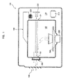
- an oven body 100 is provided with a cooking chamber 120 and an electric device chamber 110.
- a high-voltage transformer 210, a magnetron 220, and an air circulation fan 230 are located in the electric device chamber 110.
- the oven body 100 is provided with a wave guide 130 that transmits microwaves generated in the magnetron 220 to the cooking chamber 120. While not shown, it is understood that additional devices can be located in the electric device chamber 110.
- a tray 240 to hold the food to be cooked and a tray motor 250 to rotate the tray 240 are placed in the cooking chamber 120.
- Air inlets 121 are formed on one side of the wall of the cooking chamber 120 to allow air circulated by the fan 230 to enter the cooking chamber 120.
- Air outlets 122 are formed on another side of the wall of the cooking chamber 120 to allow air having entered the cooking chamber 120 through the air inlets 121 to be discharged from the cooking chamber 120.
- a humidity detector 260 is mounted on the outside of the wall of the cooking chamber 120 opposite the air outlets 122. It is understood that the tray 240 and the tray motor 250 need not be present in all circumstances. Further, it is understood that ones of the air outlets 122 may be disposed on additional walls.
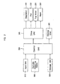
- the microwave oven has a control unit 330 to control an overall operation of the microwave oven.
- the control unit 330 may be a general or special purpose computer, depending on the circumstances.
- An input unit 210 to receive cooking commands from a user and which is in communication with the control unit 330.
- the humidity detector 260 is in communication with the control unit 330.
- a storage unit 320 to store operating software and cooking information data is in communication with the control unit 330.
- a drive unit 340 is used to operate the magnetron 220, the fan 230, the tray motor 250 and an alarm 350, which aurally informs a user of the operation of the microwave oven.
- the drive unit 340 is in communication with the control unit 330.
- a display unit 360 is in communication with the control unit 330 and is controlled by the control unit 330. It is understood that additional elements may be added or ones of the shown elements may be removed according to a desired functionality of the microwave oven.
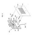
- FIG 3 is a perspective view showing humidity detector 260.
- a first electrode 262a and a second electrode 262b are formed on a non-conductive board 261, such as a printed circuit board (PCB) or a PCB having a coating such as a ceramic coating and/or a polymer coating.
- PCB printed circuit board
- a coating such as a ceramic coating and/or a polymer coating.
- the electrodes 262a, 262b are of copper, gold, or other conductive material.
- the first and second electrodes 262a and 262b are spaced apart from each other by a certain distance to form a gap there between.
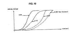
- the gap is shown as less than of equal to 0.18 mm, but may be wider up to 0.25 mm according to a desired resistance of the humidity detector 260.
- the air outlet from the cooking chamber 120 is deflected at the board 261 within the gap, wherein the moisture content of the air changes a resistance between the electrodes 262a, 262b indicating amount of the moisture in the air.
- the humidity detector 260 becomes susceptible to sudden changes in sensing values and is thus too sensitive for the purposes of cooking food in a microwave oven.
- the humidity detector 260 is not sensitive enough for the purposes of cooking food in a microwave oven.
- the humidity detector 260 is better suited for cooking food in a microwave oven.
- the gap is 0.15 mm.
- other gap distances can be used in microwave ovens, and that the gap distances can be varied based on uses other than in microwave ovens according to a desired sensitivity and other factors.
- a first detection electrode 263a is formed by plating one end of the first electrode 262a sequentially with nickel and gold so as to prevent oxidation due to moisture.
- a first wire 264a is attached to the other end of the first electrode 262a connect the first electrode 262a with the another device/element (not shown).
- a second detection electrode 263b is formed by plating one end of the second electrode 262b sequentially with nickel and gold so as to prevent oxidation due to moisture.
- a second wire 264b is connected to the other end of the second electrode 262a so as to connect the second electrode 262b with another device/element (not shown).
- other types of materials can be used for the board 261, electrodes 262a, 262b and the detection electrodes 263a, 263b.
- Two detection slits 265 are formed above and below the first and second electrodes 262a and 262b to allow air discharged through the air outlets 122 to pass through.
- the detecting slits 265 have an area equal to or greater than twice the area of the first and second detecting electrodes 263a and 263b. The detection slits 265 need not be used in all circumstances.
- Attaching holes 266 are formed to attach the humidity detector 260 to a wall of the cooking chamber 120.
- the humidity detector 260 is attached to the wall of the cooking chamber 120 with a plurality of spacers 267 inserted into the attaching holes 266 and a plurality of attaching holes 123 formed in the wall of the cooking chamber 120.
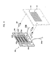
- the first and second electrodes 262a, 262b are provided in the form of interlocked combs by having multiple pairs of first and second detecting electrodes 263a and 236b such that the first and second detecting electrodes 263a and 263b are provided in the form of lines.
- the other construction of the humidity detector 260 is otherwise the same as the corresponding construction of the humidity detector of Figure 3 .
- the use of multiple pairs of detecting electrodes 263a, 263b increases a sensitivity of the humidity detector 260.
- the first wire 264a is connected to the first electrode 262a and to the anode of a direct current source DC of 5 volts.
- the cathode of the direct current source DC is grounded.
- the second wire 264b is connected to the second electrode 262b and to the control unit 330.
- a resistor R and a capacitor C are each connected in parallel with the second wire 264b and the ground.
- the resistor R has a value ranging 200 to 500k ⁇ , but can be varied depending on a voltage of the direct current source DC. It is understood that the connection directions of the first and second wires 264a and 264b respectively connected to the first and second electrodes 262a and 262b may be changed with each other.
- a direct current voltage of about 5 volts is supplied to the second electrode 262b through the second wire 264b from the control unit 330.
- the first electrode 262a is connected to the control unit 330 through the first wire 264a.
- a resistor R and a capacitor C are each connected in parallel with the first wire 264a and the ground.
- the resistor R has a value ranging 200 to 500k ⁇ , but can be varied depending on the direct current voltage. It is understood that the connection directions of the first and second wires 264a and 264b respectively connected to the first and second electrodes 262a and 262b may be changed with each other.
- the resistance between the first and second detecting electrodes 263a and 263b is determined by the cross section of and the length between the first and second detecting electrodes 263a and 263b.
- the length is constant, so the resistance only depends on the cross section of the first and second detecting electrodes 263a and 263b. If there is no moisture or vapour in the space between the first and second detecting electrodes 263a and 263b, the value of the resistance becomes infinite, thus forming an open circuit. If there moisture or vapour in the space between the first and second detecting electrodes 263a and 263b, the value of the resistance is reduced, thereby allowing a current to flow between the first and second detecting electrodes 263a and 263b. The amount of the current reflects the moisture content of the air received between the detecting electrodes 263a, 263b.
- the food is heated by microwaves generated by the magnetron 220.
- Moisture formed while heating the food is detected by the humidity detector 260.
- the heating time of the microwave oven is varied depending on the amount of food.
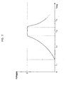
- the load according to the amount of food is determined by measuring a first time period T1, during which no moisture was formed after the initiation of the cooking operation (i.e., the humidity detector 260 does not produce a voltage).
- the first time period T1 When a certain time period according to the amount of food (the first time period T1), has elapsed, the formation of moisture from the food begins and the amount of moisture in the air output from the cooking chamber 120 increases. The moisture or gas remains on the board 261 in the space between the first and second detecting electrodes 263a and 263b of the humidity detector 260.
- the resistance between the first and second detecting electrodes 263a and 263b is reduced, thereby increasing the output voltage of the humidity detector 260.
- the output voltage of the humidity detector 260 gradually increases to reach the voltage of the direct current source DC.
- the output voltage of the humidity detector 260 equals the voltage provided by the direct current source DC, the food has reached its boiling point.
- the time period between which the output voltage of the humidity detector 260 has reached the voltage of the direct current source DC and when the formation of moisture begins is a second time period T2.
- the output voltage of the humidity detector 260 remains constant. In the shown embodiment, the voltage would be 5 Volts, which is the voltage of the direct current source DC.
- the third time period T3, during which the output voltage of the humidity detector 260 remaining constant, varies depending on the amount of food and the amount of the moisture contained in the food. Accordingly, the amount of the moisture contained in the food can be determined by measuring the third time period T3.
- the drying time period of the food can be determined by measuring the fourth time period T4.
- the cooking state determination data relating to the first to fourth time period T1 to T4 are stored in the storage unit 320 for various foods.
- the storage unit 320 can be updated to account for new foods and refined cooking techniques using portable storage media or through a network connection such as through the internet.
- the control unit 330 automatically or manually sets the cooking information so as to cook the food (S10).
- a user inputs an automatic cooking command, or directly inputs the cooking information through the input unit 310.
- the input unit 310 transmits a signal corresponding to the information provided by the user to the control unit 330.
- the control unit 330 automatically or manually sets the cooking information in response to the signal transmitted from the input unit 310.
- control unit 330 After the cooking information has been set, the control unit 330 starts the cooking operation through the drive unit 340, which operates the magnetron 220, the tray motor 250, the fan 230, and any other similar devices (S20). Additionally, the control unit 330 controls the display unit 360 to display a variety of messages related to the cooking operation.
- the control unit 330 detects the humidity (S30) in the air from the cooking chamber 120 using the humidity detector 260.
- the control unit 330 converts a voltage signal transmitted from the humidity detector 260 into a digital signal, and detects the humidity according to the value of the digital signal.
- the control unit 330 determines the cooking state of the food according to the value of humidity detected by the humidity detector 260 at the step S30 (S40). Specifically, the control unit 330 determines the cooking state of the food according to the cooking state determination data set in advance (i.e., based upon known values for T 1 , T 2 , T 3 and/or T 4 ). The control unit 330 resets the cooking information, such as the cooking time and an amount of cooking electricity, according to the cooking state determined at the step S40 (S50).
- control unit 330 determines whether the cooking operation is completed (S60). If the cooking operation is not completed because a cooking time has not elapsed, the control unit 300 continues the cooking operation. If the cooking operation is completed because the cooking time elapses, the control unit 300 controls the drive unit 340 to stop the operation of the magnetron 220, the tray motor 250 and the fan 230, thus stopping the cooking operation (S70).
- the present invention provides a microwave oven with a humidity detector, which has simple construction, so the humidity detector can be easily and inexpensively fabricated with a superior reliability.
- the humidity detector according to the present invention could be used with other appliances such as convection ovens or other heating devices, in air conditioning systems such as in HVAC or humidifying systems, or in any application where humidity needs to be detected.
Landscapes
- Chemical & Material Sciences (AREA)
- Engineering & Computer Science (AREA)
- Physics & Mathematics (AREA)
- Life Sciences & Earth Sciences (AREA)
- Biochemistry (AREA)
- Mechanical Engineering (AREA)
- General Engineering & Computer Science (AREA)
- Chemical Kinetics & Catalysis (AREA)
- Electrochemistry (AREA)
- Health & Medical Sciences (AREA)
- Electromagnetism (AREA)
- Analytical Chemistry (AREA)
- Combustion & Propulsion (AREA)
- General Health & Medical Sciences (AREA)
- General Physics & Mathematics (AREA)
- Immunology (AREA)
- Pathology (AREA)
- Electric Ovens (AREA)
- Control Of High-Frequency Heating Circuits (AREA)
- Investigating Or Analyzing Materials By The Use Of Electric Means (AREA)
- Investigating Or Analyzing Materials By The Use Of Fluid Adsorption Or Reactions (AREA)
Claims (10)
- Four à micro-ondes possédant un capteur d'humidité (260) caractérisé en ce que le capteur d'humidité (260) comprend un substrat non conducteur (261) ayant au moins un évent (265) disposé de manière à permettre à l'air de passer à travers, et des première et deuxième électrodes (263a, 263b) sur le substrat (261), les électrodes (263a, 263b) étant séparées par un entrefer.
- Four à micro-ondes selon la revendication 1, dans lequel le substrat non conducteur (261) comprend une couche en céramique ou polymère qui est formée sur le substrat (261) afin de former le fond de l'entrefer.
- Four à micro-ondes selon la revendication 1 ou la revendication 2, dans lequel le substrat (261) comprend un circuit imprimé.
- Four à micro-ondes selon la revendication 1, la revendication 2 ou la revendication 3, dans lequel les électrodes (263a, 263b) comportent des couches anticorrosion.
- Four à micro-ondes selon la revendication 4, dans lequel les couches anticorrosion comprennent une couche d'or et une couche de nickel.
- Four à micro-ondes selon l'une quelconque des revendications précédentes, dans lequel la largeur de l'entrefer entre les électrodes se situe dans la plage de 0,05 mm à 0,25 mm.
- Four à micro-ondes selon l'une quelconque des revendications précédentes, dans lequel l'évent (265) comprend une pluralité de fentes de détection ayant une aire de surface égale ou supérieure à deux fois l'aire de surface des première et deuxième électrodes de détection.
- Four à micro-ondes selon l'une quelconque des revendications précédentes, comprenant en plus une résistance et un condensateur, ladite résistance et ledit condensateur étant connectés chacun en parallèle entre la deuxième électrode (263b) et une masse.
- Four à micro-ondes selon l'une quelconque des revendications précédentes, comprenant:un magnétron (260) pour générer des ondes micrométriques ;une chambre de cuisson (120) pour la cuisson des aliments à cuire en utilisant les ondes micrométriques générées ;le capteur d'humidité (260) étant prévu pour recevoir l'air chargé d'humidité qui est évacué de ladite chambre de cuisson (120) ; etun module de commande (330) pour commander ledit magnétron (220) en fonction de l'humidité détectée par ledit capteur d'humidité (260).
- Four à micro-ondes selon la revendication 10, comprenant en plus :des trous de fixation (123, 266) formés dans une paroi de ladite chambre de cuisson (120) et dans le substrat (261), etdes entretoises (267),dans lequel ledit capteur d'humidité (260) est monté sur la paroi de ladite chambre de cuisson (120) en utilisant lesdites entretoises (267) introduites dans lesdits trous de fixation.
Applications Claiming Priority (4)
| Application Number | Priority Date | Filing Date | Title |
|---|---|---|---|
| US5312 | 1995-10-16 | ||
| KR2001047535 | 2001-08-07 | ||
| KR20010047535 | 2001-08-07 | ||
| US10/005,312 US6835920B2 (en) | 2001-08-07 | 2001-12-07 | Microwave oven |
Publications (3)
| Publication Number | Publication Date |
|---|---|
| EP1283661A2 EP1283661A2 (fr) | 2003-02-12 |
| EP1283661A3 EP1283661A3 (fr) | 2005-08-17 |
| EP1283661B1 true EP1283661B1 (fr) | 2010-12-15 |
Family
ID=26639282
Family Applications (1)
| Application Number | Title | Priority Date | Filing Date |
|---|---|---|---|
| EP02253058A Expired - Lifetime EP1283661B1 (fr) | 2001-08-07 | 2002-04-30 | Capteur d'humidité et four à micro-ondes possédant un capteur d'humidité |
Country Status (3)
| Country | Link |
|---|---|
| EP (1) | EP1283661B1 (fr) |
| KR (1) | KR20030013234A (fr) |
| CN (1) | CN1172561C (fr) |
Cited By (1)
| Publication number | Priority date | Publication date | Assignee | Title |
|---|---|---|---|---|
| TWI495871B (zh) * | 2011-11-04 | 2015-08-11 | Grand Mate Co Ltd | Humidity detection device and detection method thereof |
Families Citing this family (2)
| Publication number | Priority date | Publication date | Assignee | Title |
|---|---|---|---|---|
| CN105276813B (zh) * | 2015-11-21 | 2018-11-09 | 滁州博明信息科技有限公司 | 一种电力加热设备 |
| CN106610037A (zh) * | 2016-12-06 | 2017-05-03 | 广东美的厨房电器制造有限公司 | 微波炉 |
Family Cites Families (9)
| Publication number | Priority date | Publication date | Assignee | Title |
|---|---|---|---|---|
| GB930737A (en) * | 1959-09-02 | 1963-07-10 | Secr Defence Brit | Sweat rate indicator |
| US4015230A (en) * | 1975-02-03 | 1977-03-29 | Matsushita Electric Industrial Co., Ltd. | Humidity sensitive ceramic resistor |
| JPS60111143A (ja) * | 1983-11-21 | 1985-06-17 | Daido Steel Co Ltd | 湿度感知素子 |
| JPH02150754A (ja) * | 1988-11-30 | 1990-06-11 | Toshiba Corp | 感応素子の製造方法 |
| KR940002558A (ko) * | 1992-07-14 | 1994-02-17 | 이헌조 | 전자레인지의 자동 요리 방법 및 장치 |
| JP3531971B2 (ja) * | 1994-05-16 | 2004-05-31 | フィガロ技研株式会社 | ガスまたは湿度を検出するセンサとその製造方法 |
| DE19600108C2 (de) * | 1995-03-07 | 1997-11-27 | Mannesmann Vdo Ag | Verfahren und Anordnung zum Betrieb eines resistiven Feuchtesensors |
| KR0154643B1 (ko) * | 1995-09-29 | 1998-11-16 | 배순훈 | 증기센서의 출력신호를 이용한 적응 제어방법 |
| KR19990005167A (ko) * | 1997-06-30 | 1999-01-25 | 배순훈 | 전자렌지의 습도센서 및 습도검출 회로 |
-
2002
- 2002-03-21 KR KR1020020015272A patent/KR20030013234A/ko not_active Ceased
- 2002-04-30 EP EP02253058A patent/EP1283661B1/fr not_active Expired - Lifetime
- 2002-05-13 CN CNB02119338XA patent/CN1172561C/zh not_active Expired - Fee Related
Cited By (1)
| Publication number | Priority date | Publication date | Assignee | Title |
|---|---|---|---|---|
| TWI495871B (zh) * | 2011-11-04 | 2015-08-11 | Grand Mate Co Ltd | Humidity detection device and detection method thereof |
Also Published As
| Publication number | Publication date |
|---|---|
| EP1283661A2 (fr) | 2003-02-12 |
| KR20030013234A (ko) | 2003-02-14 |
| CN1172561C (zh) | 2004-10-20 |
| CN1402596A (zh) | 2003-03-12 |
| EP1283661A3 (fr) | 2005-08-17 |
Similar Documents
| Publication | Publication Date | Title |
|---|---|---|
| US6875969B2 (en) | Microwave oven and method of controlling the same | |
| CA1138938A (fr) | Four combine a microondes et elements electriques a commande selective sensible a la sortie du detecteur de gaz ou d'une thermistance | |
| KR100503757B1 (ko) | 전자레인지와 그 제어방법 | |
| EP0031156B1 (fr) | Four de cuisine avec détecteur d'humidité en céramique | |
| US6774347B2 (en) | Microwave oven with humidity sensor | |
| EP1283661B1 (fr) | Capteur d'humidité et four à micro-ondes possédant un capteur d'humidité | |
| US6835920B2 (en) | Microwave oven | |
| EP1790913A2 (fr) | Plaque chauffante et appareil de cuisson à vapeur comportant celle-ci | |
| KR20030081844A (ko) | 전자레인지 | |
| KR20030079385A (ko) | 전자렌지 및 그 제어방법 | |
| CN1972538A (zh) | 板式加热器及包含板式加热器的蒸汽烹饪装置 | |
| KR20060122128A (ko) | 전자레인지의 쿨링시간 제어장치 및 그 방법 | |
| EP1353535B1 (fr) | Procédé et appareillage de commande d'un four à micro-ondes | |
| KR100248781B1 (ko) | 전자 렌지의 운전 제어 장치 | |
| KR200224579Y1 (ko) | 후드겸용 전자레인지의 벤트팬 구동장치 | |
| KR20260026405A (ko) | 조리 기기 | |
| KR100730934B1 (ko) | 다수의 습도센서를 구비한 전자레인지 | |
| JPH05312326A (ja) | 加熱調理器 | |
| JP2984476B2 (ja) | 加熱調理器 | |
| KR100283655B1 (ko) | 전자렌지의 조리상태 자기진단방법 | |
| JPH06313553A (ja) | 電子レンジ | |
| JPH05240445A (ja) | 加熱調理器 | |
| JPH0831563A (ja) | 自動加熱装置および気体センサ | |
| JP2006162181A (ja) | 高周波加熱調理装置 | |
| KR19980017806U (ko) | 전자렌지의 구동제어방법 |
Legal Events
| Date | Code | Title | Description |
|---|---|---|---|
| PUAI | Public reference made under article 153(3) epc to a published international application that has entered the european phase |
Free format text: ORIGINAL CODE: 0009012 |
|
| AK | Designated contracting states |
Designated state(s): AT BE CH CY DE DK ES FI FR GB GR IE IT LI LU MC NL PT SE TR |
|
| AX | Request for extension of the european patent |
Extension state: AL LT LV MK RO SI |
|
| RAP1 | Party data changed (applicant data changed or rights of an application transferred) |
Owner name: SAMSUNG ELECTRONICS CO., LTD. |
|
| PUAL | Search report despatched |
Free format text: ORIGINAL CODE: 0009013 |
|
| AK | Designated contracting states |
Kind code of ref document: A3 Designated state(s): AT BE CH CY DE DK ES FI FR GB GR IE IT LI LU MC NL PT SE TR |
|
| AX | Request for extension of the european patent |
Extension state: AL LT LV MK RO SI |
|
| RIC1 | Information provided on ipc code assigned before grant |
Ipc: 7H 05B 6/68 A Ipc: 7G 01N 27/04 B |
|
| 17P | Request for examination filed |
Effective date: 20051222 |
|
| AKX | Designation fees paid |
Designated state(s): DE FR GB |
|
| GRAP | Despatch of communication of intention to grant a patent |
Free format text: ORIGINAL CODE: EPIDOSNIGR1 |
|
| GRAS | Grant fee paid |
Free format text: ORIGINAL CODE: EPIDOSNIGR3 |
|
| GRAA | (expected) grant |
Free format text: ORIGINAL CODE: 0009210 |
|
| AK | Designated contracting states |
Kind code of ref document: B1 Designated state(s): DE FR GB |
|
| REG | Reference to a national code |
Ref country code: GB Ref legal event code: FG4D |
|
| REF | Corresponds to: |
Ref document number: 60238584 Country of ref document: DE Date of ref document: 20110127 Kind code of ref document: P |
|
| PLBE | No opposition filed within time limit |
Free format text: ORIGINAL CODE: 0009261 |
|
| STAA | Information on the status of an ep patent application or granted ep patent |
Free format text: STATUS: NO OPPOSITION FILED WITHIN TIME LIMIT |
|
| 26N | No opposition filed |
Effective date: 20110916 |
|
| REG | Reference to a national code |
Ref country code: DE Ref legal event code: R097 Ref document number: 60238584 Country of ref document: DE Effective date: 20110916 |
|
| REG | Reference to a national code |
Ref country code: FR Ref legal event code: PLFP Year of fee payment: 14 |
|
| PGFP | Annual fee paid to national office [announced via postgrant information from national office to epo] |
Ref country code: DE Payment date: 20150409 Year of fee payment: 14 Ref country code: GB Payment date: 20150410 Year of fee payment: 14 |
|
| PGFP | Annual fee paid to national office [announced via postgrant information from national office to epo] |
Ref country code: FR Payment date: 20150413 Year of fee payment: 14 |
|
| REG | Reference to a national code |
Ref country code: DE Ref legal event code: R119 Ref document number: 60238584 Country of ref document: DE |
|
| GBPC | Gb: european patent ceased through non-payment of renewal fee |
Effective date: 20160430 |
|
| REG | Reference to a national code |
Ref country code: FR Ref legal event code: ST Effective date: 20161230 |
|
| PG25 | Lapsed in a contracting state [announced via postgrant information from national office to epo] |
Ref country code: GB Free format text: LAPSE BECAUSE OF NON-PAYMENT OF DUE FEES Effective date: 20160430 Ref country code: DE Free format text: LAPSE BECAUSE OF NON-PAYMENT OF DUE FEES Effective date: 20161101 Ref country code: FR Free format text: LAPSE BECAUSE OF NON-PAYMENT OF DUE FEES Effective date: 20160502 |