EP1283802B1 - Transport- und lagervorrichtung - Google Patents
Transport- und lagervorrichtung Download PDFInfo
- Publication number
- EP1283802B1 EP1283802B1 EP01921159A EP01921159A EP1283802B1 EP 1283802 B1 EP1283802 B1 EP 1283802B1 EP 01921159 A EP01921159 A EP 01921159A EP 01921159 A EP01921159 A EP 01921159A EP 1283802 B1 EP1283802 B1 EP 1283802B1
- Authority
- EP
- European Patent Office
- Prior art keywords
- inner container
- cover plate
- container
- outer container
- opening
- Prior art date
- Legal status (The legal status is an assumption and is not a legal conclusion. Google has not performed a legal analysis and makes no representation as to the accuracy of the status listed.)
- Revoked
Links
- 239000007788 liquid Substances 0.000 claims abstract description 6
- 239000003566 sealing material Substances 0.000 claims 1
- 239000000463 material Substances 0.000 description 7
- 239000002184 metal Substances 0.000 description 4
- 238000005429 filling process Methods 0.000 description 3
- 238000007789 sealing Methods 0.000 description 3
- 239000000945 filler Substances 0.000 description 2
- 238000000034 method Methods 0.000 description 1
- 238000012986 modification Methods 0.000 description 1
- 230000004048 modification Effects 0.000 description 1
- 230000000087 stabilizing effect Effects 0.000 description 1
- 239000000126 substance Substances 0.000 description 1
Images

Classifications
-
- B—PERFORMING OPERATIONS; TRANSPORTING
- B65—CONVEYING; PACKING; STORING; HANDLING THIN OR FILAMENTARY MATERIAL
- B65D—CONTAINERS FOR STORAGE OR TRANSPORT OF ARTICLES OR MATERIALS, e.g. BAGS, BARRELS, BOTTLES, BOXES, CANS, CARTONS, CRATES, DRUMS, JARS, TANKS, HOPPERS, FORWARDING CONTAINERS; ACCESSORIES, CLOSURES, OR FITTINGS THEREFOR; PACKAGING ELEMENTS; PACKAGES
- B65D77/00—Packages formed by enclosing articles or materials in preformed containers, e.g. boxes, cartons, sacks or bags
- B65D77/04—Articles or materials enclosed in two or more containers disposed one within another
- B65D77/06—Liquids or semi-liquids or other materials or articles enclosed in flexible containers disposed within rigid containers
-
- B—PERFORMING OPERATIONS; TRANSPORTING
- B65—CONVEYING; PACKING; STORING; HANDLING THIN OR FILAMENTARY MATERIAL
- B65D—CONTAINERS FOR STORAGE OR TRANSPORT OF ARTICLES OR MATERIALS, e.g. BAGS, BARRELS, BOTTLES, BOXES, CANS, CARTONS, CRATES, DRUMS, JARS, TANKS, HOPPERS, FORWARDING CONTAINERS; ACCESSORIES, CLOSURES, OR FITTINGS THEREFOR; PACKAGING ELEMENTS; PACKAGES
- B65D77/00—Packages formed by enclosing articles or materials in preformed containers, e.g. boxes, cartons, sacks or bags
- B65D77/04—Articles or materials enclosed in two or more containers disposed one within another
- B65D77/0446—Articles or materials enclosed in two or more containers disposed one within another the inner and outer containers being rigid or semi-rigid and the outer container being of polygonal cross-section not formed by folding or erecting one or more blanks
- B65D77/0453—Articles or materials enclosed in two or more containers disposed one within another the inner and outer containers being rigid or semi-rigid and the outer container being of polygonal cross-section not formed by folding or erecting one or more blanks the inner container having a polygonal cross-section
- B65D77/0466—Articles or materials enclosed in two or more containers disposed one within another the inner and outer containers being rigid or semi-rigid and the outer container being of polygonal cross-section not formed by folding or erecting one or more blanks the inner container having a polygonal cross-section the containers being mounted on a pallet
Definitions
- the invention relates to a device for transport and / or storage of an in particular liquid medium from a relatively thin-walled, the medium absorbing Inner container made of plastic and the same tub-like enclosing outer container, the inner container at the top is a filler opening designed as a threaded socket and if necessary has an emptying opening at the bottom, the outer container from a pallet like the inner container on his Underside supporting support body and one on the support body subsequent jacket body and the inner container through a cover plate attached to the outer container in the outer container is secured.
- Liquid media such as chemicals
- transport containers recorded, transported and stored, the one Have a volume of about 500 to 1500 1.
- Such Devices consist of an inner container and an outer container.
- the inner container is thin-walled and made of plastic and has a top as a nozzle with external thread shaped filler opening, which is formed by a Screw lid can be closed. Usually below is one with provided a closure part emptying opening.
- the outer container has a tub-like shape.
- the outer container consists of one pallet-like support body on which the inner container is supported. To the Support body is followed by a jacket body made of metal or plastic can exist.
- the jacket body of the outer container is almost over his entire surface firmly, i.e. without any noticeable play, on the jacket side of the inner container on.
- the inner container is in the outer container via a special cover plate secured, usually with a collar to the top of the outer container engages and is screwed to it.
- the document DE-A-198 02 307 describes a device according to the preamble of claim 1.
- the device has a cover plate with the edge of a Outer container is screwed.
- the cover plate has an opening that seals with a nozzle for the inner container. Overflowing material is going along the cover plate forwarded laterally and via a drain device dissipated outside.
- the container wall 41 has a nozzle in the upper area, which is opposite an upper edge of the container is sunk.
- the sink is as an overflow channel trained along the overflowing material is guided to the outside.
- WO-A-95/03231 From WO-A-95/03231 is a pallet container with a bottom pallet and one plastic inner container arranged thereon described.
- the inner container has a nozzle that sinks towards the top of the inner container is arranged.
- the recess in the inner container forms a channel in which overflowing material is led outside.
- the invention has for its object to continue the known device form that filling material running alongside it no longer between the inner container and the outer container can get.
- the device according to the invention Genus described above suggested that on the top of the inner container a cover plate provided with a recess is provided that the depression has an opening sealingly against the nozzle and that from this recess at least one overflow channel to the side of the outer container extends.
- This configuration means that there is an ongoing process during the filling process Medium or product is first collected from the recess and then immediately over the overflow channel to the side derived. In the area between the inner container and outer container this means that no filling material running alongside can reach it.
- Fig. 1 of the drawing is a device for storage and / or for transporting in particular liquid medium in Perspective representation shown, which first of all relatively thin-walled inner container 1 from a suitable Plastic is made.
- the inner container 1 has a cubic, rounded at the corners and edges and has above one formed by a socket 2 with an external thread Filling opening closed by a screw cap is.
- a socket 2 with an external thread Filling opening closed by a screw cap is.
- the inner container 1 is inserted into an outer container 4, which is also made of plastic, for example.
- the outer container but can also be made of metal, for example sheet metal his.
- This outer container 4 has a pallet-like Support body 5 on which the inner container 1 is supported.
- At the side edges of the support body 5 includes Sheath body 6 on which the inner container 1 largely over its entire circumferential outer surface is in contact. So that supports Sheath body 6 also the relatively thin inner container 1 lateral off.
- the top protrudes Edge 7 of the jacket body 6 by a predetermined amount over the top surface of the inner container 1 also.
- On this edge 7 is a cover plate 8 made of metal or plastic with a mounting edge 14 attached.
- the fastening edge 14 can for example be screwed to the edge 7.
- the cover plate 8 has a recess 9 with an opening 10 the nozzle 2 engages and is sealed against the same.
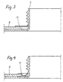
- This seal is achieved according to Figures 3 and 4 by a seal 11, which are either glued to the cover plate 8 or in the opening of the cover plate 8 is attached. With appropriate Design of the seal 11 and the cover plate 8 is prevented that the so-called top of the inner container 1 can lower.
- the mounting edge 14 of the cover plate 8, the engages around the opposite edges 7 of the jacket body 6, causes a stabilizing function of the Sheath body 6 and thus the device.
- the recess 9 surrounding the nozzle 2 goes seamlessly into two overflow channels 12 over, which lead to the outside and in Embodiment of FIG. 1 each open into an opening 13, which are incorporated into the mounting edge 14 of the cover plate 8 are. If necessary, the upper edge 7 of the Sheath body 6 has a recess. Via the recess 9, the Overflow channels 12 and the openings 13 can during the filling process adjacent filling material can be easily discharged to the outside.
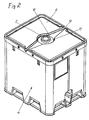
- the exemplary embodiment according to FIG. 2 differs from that the embodiment of FIG. 1 in that 2, the cover plate 8 over the entire upper surface of the Sheath body 6 and thus the device extends. Further there are no openings in the mounting edge 14 of the cover plate 8 13 provided. The fastening edge 14 is rather interrupted, so that the overflow channels 12 lead directly to the outside. Such a configuration can also be used for the cover plate 8 1 and vice versa.
- the Seal 11 can also be designed and arranged differently. It is possible, the cover plate 8 itself from a sealing elastic Form material. It is also possible to attach the edge 14 differently.
Landscapes
- Engineering & Computer Science (AREA)
- Mechanical Engineering (AREA)
- Packages (AREA)
- Pallets (AREA)
- Details Of Rigid Or Semi-Rigid Containers (AREA)
- Rigid Containers With Two Or More Constituent Elements (AREA)
- Refuse Collection And Transfer (AREA)
- Automatic Disk Changers (AREA)
Description
- Fig. 1
- eine erfindungsgemäße Vorrichtung,
- Fig. 2
- eine andere Ausgestaltung einer Vorrichtung gemäß der Erfindung,
- Fig. 3
- eine Abdichtung des Stutzens des Innenbehälters und
- Fig. 4
- eine andere Ausbildung einer Abdichtung.
Claims (6)
- Vorrichtung zum Transport und/oder Lagerung eines insbesondere flüssiger Mediums, bestehend aus einem verhältnismäßig dünnwandigen, das Medium aufnehmenden Innenbehälter (1) aus Kunststoff und einem denselben wannenartig umschließenden Außenbehälter (4), wobei der lnnenbehälter (1) oben eine als Stutzen (2) mit Gewinde ausgebildete Einfüllöffnung und bedarfsweise unten eine Entleeröffnung aufweist, der Außenbehälter (4) aus einem palettenartigen, den Innenbehälter (1) an seiner Unterseite abstützenden Tragkörper (5) und einem sich an den Tragkörper (5) anschließenden Mantelkörper (6) besteht und der Innenbehälter (1) durch eine am Außenbehälter (4) befestigte Deckplatte (8) im Außenbehälter (4) gesichert ist;
dadurch gekennzeichnet, daß die an der Oberseite des Innenbehälters (1) vorgesehene Deckplatte (8) mit einer Vertiefung (9) versehen ist, dass die Vertiefung (9) eine dichtend am Stutzen (2) anliegende Öffnung (10) besitzt und dass sich von dieser Vertiefung (9) mindestens eine Überlaufrinne (12) bis seitlich über den Außenbehälter (4) erstreckt. - Vorrichtung nach Anspruch 1,
dadurch gekennzeichnet, daß die Deckplatte (8) zwei sich gegenüberliegende Überlaufrinnen (12) aufweist. - Vorrichtung nach Anspruch 1 oder 2,
dadurch gekennzeichnet, dass die Deckplatte (8) einen Befestigungsrand (14) aufweist und sich die Überlaufrinne (12) durch den Befestigungsrand (14) erstreckt. - Vorrichtung nach Anspruch 1 oder 2,
dadurch gekennzeichnet, dass die Überlaufrinne (12) in einen Befestigungsrand (14) der Deckplatte (8) eingeformt ist. - Vorrichtung nach mindestens einem der Ansprüche 1 bis 4,
dadurch gekennzeichnet, dass die Öffnung (10) der Deckplatte (8) über einen Dichtring (11) an dem Stutzen (2) anliegt - Vorrichtung nach mindestens einem der Ansprüche 1 bis 4,
dadurch gekennzeichnet, dass die Deckplatte (8) aus einem dichtungselastischen Werkstoff gebildet ist.
Applications Claiming Priority (3)
| Application Number | Priority Date | Filing Date | Title |
|---|---|---|---|
| DE20009113U | 2000-05-22 | ||
| DE20009113U DE20009113U1 (de) | 2000-05-22 | 2000-05-22 | Transport- und Lagervorrichtung |
| PCT/DE2001/000799 WO2001089942A1 (de) | 2000-05-22 | 2001-03-02 | Transport- und lagervorrichtung |
Publications (2)
| Publication Number | Publication Date |
|---|---|
| EP1283802A1 EP1283802A1 (de) | 2003-02-19 |
| EP1283802B1 true EP1283802B1 (de) | 2004-06-23 |
Family
ID=7941813
Family Applications (1)
| Application Number | Title | Priority Date | Filing Date |
|---|---|---|---|
| EP01921159A Revoked EP1283802B1 (de) | 2000-05-22 | 2001-03-02 | Transport- und lagervorrichtung |
Country Status (11)
| Country | Link |
|---|---|
| US (1) | US7150373B2 (de) |
| EP (1) | EP1283802B1 (de) |
| JP (1) | JP2003534207A (de) |
| KR (1) | KR100774037B1 (de) |
| CN (1) | CN1164461C (de) |
| AT (1) | ATE269815T1 (de) |
| BR (1) | BR0110958A (de) |
| CA (1) | CA2410301C (de) |
| DE (2) | DE20009113U1 (de) |
| MX (1) | MXPA02011239A (de) |
| WO (1) | WO2001089942A1 (de) |
Families Citing this family (6)
| Publication number | Priority date | Publication date | Assignee | Title |
|---|---|---|---|---|
| DE20107962U1 (de) | 2001-05-11 | 2002-06-20 | Honeywell Speciality Chemicals Seelze GmbH, 30926 Seelze | Transport- und/oder Lagerungsvorrichtung |
| US20040173615A1 (en) * | 2003-03-07 | 2004-09-09 | Goodman John B. | Fuel storage container for a fuel cell |
| US8162164B2 (en) * | 2007-04-19 | 2012-04-24 | Podd Stephen D | Bulk liquid transport system |
| US10179333B2 (en) * | 2015-09-23 | 2019-01-15 | Premier Lab Supply Inc. | Integral cap sample cup |
| DE102017211560B3 (de) * | 2017-07-06 | 2018-07-26 | BSH Hausgeräte GmbH | Wäschepflegegerät mit einer Verschlussklappe |
| CN111517270B (zh) * | 2020-04-24 | 2023-04-07 | 华东师范大学 | 一种可实现高效更换与安装原子气室的高适配性容器 |
Family Cites Families (24)
| Publication number | Priority date | Publication date | Assignee | Title |
|---|---|---|---|---|
| US2952379A (en) * | 1955-09-12 | 1960-09-13 | Clifford S Potter | Collapsible containers |
| US3964636A (en) * | 1974-02-27 | 1976-06-22 | Houston Rehrig | Box for encasing a bag containing liquid |
| US4054219A (en) * | 1976-05-26 | 1977-10-18 | Beatrice Foods | Drainable container base |
| US4676373A (en) * | 1984-11-20 | 1987-06-30 | Helmhold Schneider | Plastic pallet container |
| DE3711728A1 (de) | 1987-04-07 | 1988-10-27 | Richter Guenter | Palettencontainer mit auslaufarmatur aus kunststoff und verfahren zur herstellung desselben |
| DE8908528U1 (de) * | 1989-07-13 | 1989-08-31 | Schütz-Werke GmbH & Co KG, 5418 Selters | Spundfaß |
| DE4041749C1 (en) | 1990-12-24 | 1992-06-11 | Henkel Kgaa, 4000 Duesseldorf, De | Container with integral pallet base - has built=in fan unit in roof with recessed ducts |
| US5226558A (en) | 1992-05-01 | 1993-07-13 | Rotonics Manufacturing, Inc. | Transportable multi-use storage container and pallet system |
| JP3076457B2 (ja) * | 1992-08-28 | 2000-08-14 | ヒゲタ醤油株式会社 | リサイクル容器 |
| FR2697810B1 (fr) | 1992-11-12 | 1995-02-24 | Monoplast | Caisse de conservation. |
| DE9306177U1 (de) * | 1993-04-23 | 1993-08-05 | Mauser-Werke GmbH, 50321 Brühl | Palettencontainer |
| DE4318966C2 (de) | 1993-06-08 | 1996-06-27 | Protechna Sa | Palettenbehälter |
| DE9311004U1 (de) | 1993-07-23 | 1993-10-14 | Mauser-Werke GmbH, 50321 Brühl | Palettencontainer |
| DE4341338A1 (de) | 1993-12-04 | 1995-06-08 | Schuetz Werke Gmbh Co Kg | Metallbehälter für den Transport und die Lagerung von Flüssigkeiten |
| US5474197A (en) | 1993-12-27 | 1995-12-12 | Perstorp Xytec | Collapsible container with reduced deflection |
| US5615798A (en) * | 1994-09-08 | 1997-04-01 | Ropak Corporation | Container incorporating liquid draining means, and related method |
| DE9414911U1 (de) | 1994-09-14 | 1994-11-10 | Protechna S.A., Freiburg/Fribourg | Palettenbehälter für den Transport und die Lagerung von Flüssigkeiten |
| DE4438739C1 (de) * | 1994-10-29 | 1995-10-26 | Schuetz Werke Gmbh Co Kg | Palettenbehälter für den Transport und die Lagerung von Flüssigkeiten |
| DE19535707A1 (de) * | 1995-09-26 | 1997-03-27 | Protechna Sa | Palettenbehälter |
| US6202844B1 (en) * | 1996-09-19 | 2001-03-20 | Roth Werke Gmbh | Pallet container |
| DE19722194C2 (de) * | 1997-05-27 | 1999-03-18 | Protechna Sa | Transport- und Lagerbehälter für Flüssigkeiten |
| US6019242A (en) * | 1997-09-11 | 2000-02-01 | Cascade Engineering, Inc. | Multi-compartment container and lid therefor |
| DE29800415U1 (de) | 1998-01-13 | 1998-04-09 | Protechna S.A., Freiburg/Fribourg | Transport- und Lagerbehälter für Flüssigkeiten |
| JP2914953B1 (ja) * | 1998-03-17 | 1999-07-05 | 株式会社シンワコーポレーション | 鋼製輸送容器の天板構造 |
-
2000
- 2000-05-22 DE DE20009113U patent/DE20009113U1/de not_active Expired - Lifetime
-
2001
- 2001-03-02 CA CA002410301A patent/CA2410301C/en not_active Expired - Fee Related
- 2001-03-02 BR BR0110958-8A patent/BR0110958A/pt not_active IP Right Cessation
- 2001-03-02 KR KR1020027015242A patent/KR100774037B1/ko not_active Expired - Fee Related
- 2001-03-02 US US10/296,183 patent/US7150373B2/en not_active Expired - Fee Related
- 2001-03-02 WO PCT/DE2001/000799 patent/WO2001089942A1/de not_active Ceased
- 2001-03-02 DE DE50102681T patent/DE50102681D1/de not_active Revoked
- 2001-03-02 MX MXPA02011239A patent/MXPA02011239A/es active IP Right Grant
- 2001-03-02 AT AT01921159T patent/ATE269815T1/de not_active IP Right Cessation
- 2001-03-02 JP JP2001586143A patent/JP2003534207A/ja active Pending
- 2001-03-02 EP EP01921159A patent/EP1283802B1/de not_active Revoked
- 2001-03-02 CN CNB018097677A patent/CN1164461C/zh not_active Expired - Fee Related
Also Published As
| Publication number | Publication date |
|---|---|
| CA2410301C (en) | 2009-06-02 |
| KR20030007613A (ko) | 2003-01-23 |
| MXPA02011239A (es) | 2003-03-10 |
| BR0110958A (pt) | 2003-04-15 |
| DE50102681D1 (de) | 2004-07-29 |
| US7150373B2 (en) | 2006-12-19 |
| CN1164461C (zh) | 2004-09-01 |
| KR100774037B1 (ko) | 2007-11-06 |
| CA2410301A1 (en) | 2002-11-21 |
| WO2001089942A1 (de) | 2001-11-29 |
| CN1430567A (zh) | 2003-07-16 |
| JP2003534207A (ja) | 2003-11-18 |
| DE20009113U1 (de) | 2000-09-14 |
| US20040050850A1 (en) | 2004-03-18 |
| EP1283802A1 (de) | 2003-02-19 |
| ATE269815T1 (de) | 2004-07-15 |
Similar Documents
| Publication | Publication Date | Title |
|---|---|---|
| DE69214107T2 (de) | Ausgabebehälter für eine viskose Flüssigkeit | |
| EP0275833A2 (de) | Kunststoffverschluss für einen Behälter mit einem als Deckel dienenden Messbecher | |
| DE1486690A1 (de) | Behaelter zum Abgeben eines fluessigen oder pulverfoermigen Materials | |
| CH651267A5 (de) | Mit einer aus kunststoff bestehenden schraubverschlusskappe versehener behaelter. | |
| DE19722628A1 (de) | Getränkedose | |
| DE602004010429T2 (de) | Behälterabdichtungssystem | |
| DE2711591A1 (de) | Behaelter fuer die abgabe von fluessigkeiten | |
| EP1387801B1 (de) | Behälteranordnung zum entnehmen und applizieren von teilmengen eines flüssigen produkts | |
| EP1283802B1 (de) | Transport- und lagervorrichtung | |
| DE9307083U1 (de) | Selbstschließender Verschluß | |
| DE2756350C2 (de) | Futterlose Verschlußkappe aus Kunststoff | |
| DE60013728T2 (de) | Vorrichtung zum Verschliessen von Flaschen, die unter Druck stehende Feüssigkeiten enthalten | |
| EP0868360B1 (de) | Verschlusskappe | |
| DE60306197T2 (de) | Gewindeverpackung mit"klick"-funktion | |
| CH687319A5 (de) | Verschluss. | |
| DE19735696A1 (de) | Flaschenausgießer | |
| DE8008018U1 (de) | Behaelter aus elastomerem Plastikmaterial | |
| DE1432236A1 (de) | Hohlstopfenverschluss aus elastischem Werkstoff fuer Kanister u.dgl.,insbesondere zur Aufnahme von unter UEberdruck stehenden Fluessigkeiten,insbesondere Bier u.dgl. | |
| DE7703482U1 (de) | Behaelter zur aufnahme einer milchdose | |
| DE9011045U1 (de) | Verschlußeinrichtung bei einem Transportbehälter | |
| CH681797A5 (en) | Integral plastics closure for pourable media - is of snap hinge type with lower part attached to cap via hinge, and spout in cover surface of lower part. | |
| DE8913144U1 (de) | Behälter für flüssiges Füllgut | |
| DE3810799A1 (de) | Becherfoermiger behaelter | |
| EP1256463A2 (de) | Aufsatz für Dosen | |
| DE7506692U (de) | Selbsttaetiges Druckausgleichsventil |
Legal Events
| Date | Code | Title | Description |
|---|---|---|---|
| PUAI | Public reference made under article 153(3) epc to a published international application that has entered the european phase |
Free format text: ORIGINAL CODE: 0009012 |
|
| 17P | Request for examination filed |
Effective date: 20021119 |
|
| AK | Designated contracting states |
Designated state(s): AT BE CH CY DE DK ES FI FR GB GR IE IT LI LU MC NL PT SE TR |
|
| AX | Request for extension of the european patent |
Extension state: AL LT LV MK RO SI |
|
| GRAP | Despatch of communication of intention to grant a patent |
Free format text: ORIGINAL CODE: EPIDOSNIGR1 |
|
| GRAS | Grant fee paid |
Free format text: ORIGINAL CODE: EPIDOSNIGR3 |
|
| GRAA | (expected) grant |
Free format text: ORIGINAL CODE: 0009210 |
|
| AK | Designated contracting states |
Kind code of ref document: B1 Designated state(s): AT BE CH CY DE DK ES FI FR GB GR IE IT LI LU MC NL PT SE TR |
|
| PG25 | Lapsed in a contracting state [announced via postgrant information from national office to epo] |
Ref country code: IT Free format text: LAPSE BECAUSE OF FAILURE TO SUBMIT A TRANSLATION OF THE DESCRIPTION OR TO PAY THE FEE WITHIN THE PRESCRIBED TIME-LIMIT;WARNING: LAPSES OF ITALIAN PATENTS WITH EFFECTIVE DATE BEFORE 2007 MAY HAVE OCCURRED AT ANY TIME BEFORE 2007. THE CORRECT EFFECTIVE DATE MAY BE DIFFERENT FROM THE ONE RECORDED. Effective date: 20040623 Ref country code: TR Free format text: LAPSE BECAUSE OF FAILURE TO SUBMIT A TRANSLATION OF THE DESCRIPTION OR TO PAY THE FEE WITHIN THE PRESCRIBED TIME-LIMIT Effective date: 20040623 Ref country code: IE Free format text: LAPSE BECAUSE OF FAILURE TO SUBMIT A TRANSLATION OF THE DESCRIPTION OR TO PAY THE FEE WITHIN THE PRESCRIBED TIME-LIMIT Effective date: 20040623 Ref country code: FI Free format text: LAPSE BECAUSE OF FAILURE TO SUBMIT A TRANSLATION OF THE DESCRIPTION OR TO PAY THE FEE WITHIN THE PRESCRIBED TIME-LIMIT Effective date: 20040623 |
|
| REG | Reference to a national code |
Ref country code: GB Ref legal event code: FG4D Free format text: NOT ENGLISH |
|
| REG | Reference to a national code |
Ref country code: CH Ref legal event code: EP |
|
| REG | Reference to a national code |
Ref country code: IE Ref legal event code: FG4D Free format text: GERMAN |
|
| REF | Corresponds to: |
Ref document number: 50102681 Country of ref document: DE Date of ref document: 20040729 Kind code of ref document: P |
|
| GBT | Gb: translation of ep patent filed (gb section 77(6)(a)/1977) |
Effective date: 20040824 |
|
| PG25 | Lapsed in a contracting state [announced via postgrant information from national office to epo] |
Ref country code: SE Free format text: LAPSE BECAUSE OF FAILURE TO SUBMIT A TRANSLATION OF THE DESCRIPTION OR TO PAY THE FEE WITHIN THE PRESCRIBED TIME-LIMIT Effective date: 20040923 Ref country code: GR Free format text: LAPSE BECAUSE OF FAILURE TO SUBMIT A TRANSLATION OF THE DESCRIPTION OR TO PAY THE FEE WITHIN THE PRESCRIBED TIME-LIMIT Effective date: 20040923 Ref country code: DK Free format text: LAPSE BECAUSE OF FAILURE TO SUBMIT A TRANSLATION OF THE DESCRIPTION OR TO PAY THE FEE WITHIN THE PRESCRIBED TIME-LIMIT Effective date: 20040923 |
|
| PG25 | Lapsed in a contracting state [announced via postgrant information from national office to epo] |
Ref country code: ES Free format text: LAPSE BECAUSE OF FAILURE TO SUBMIT A TRANSLATION OF THE DESCRIPTION OR TO PAY THE FEE WITHIN THE PRESCRIBED TIME-LIMIT Effective date: 20041004 |
|
| LTIE | Lt: invalidation of european patent or patent extension |
Effective date: 20040623 |
|
| PG25 | Lapsed in a contracting state [announced via postgrant information from national office to epo] |
Ref country code: CY Free format text: LAPSE BECAUSE OF FAILURE TO SUBMIT A TRANSLATION OF THE DESCRIPTION OR TO PAY THE FEE WITHIN THE PRESCRIBED TIME-LIMIT Effective date: 20050302 Ref country code: LU Free format text: LAPSE BECAUSE OF NON-PAYMENT OF DUE FEES Effective date: 20050302 Ref country code: AT Free format text: LAPSE BECAUSE OF NON-PAYMENT OF DUE FEES Effective date: 20050302 |
|
| PLAQ | Examination of admissibility of opposition: information related to despatch of communication + time limit deleted |
Free format text: ORIGINAL CODE: EPIDOSDOPE2 |
|
| PLBQ | Unpublished change to opponent data |
Free format text: ORIGINAL CODE: EPIDOS OPPO |
|
| REG | Reference to a national code |
Ref country code: IE Ref legal event code: FD4D |
|
| ET | Fr: translation filed | ||
| PLBI | Opposition filed |
Free format text: ORIGINAL CODE: 0009260 |
|
| PLAQ | Examination of admissibility of opposition: information related to despatch of communication + time limit deleted |
Free format text: ORIGINAL CODE: EPIDOSDOPE2 |
|
| PLAR | Examination of admissibility of opposition: information related to receipt of reply deleted |
Free format text: ORIGINAL CODE: EPIDOSDOPE4 |
|
| PLBQ | Unpublished change to opponent data |
Free format text: ORIGINAL CODE: EPIDOS OPPO |
|
| PG25 | Lapsed in a contracting state [announced via postgrant information from national office to epo] |
Ref country code: MC Free format text: LAPSE BECAUSE OF NON-PAYMENT OF DUE FEES Effective date: 20050331 Ref country code: LI Free format text: LAPSE BECAUSE OF NON-PAYMENT OF DUE FEES Effective date: 20050331 Ref country code: CH Free format text: LAPSE BECAUSE OF NON-PAYMENT OF DUE FEES Effective date: 20050331 |
|
| PLAB | Opposition data, opponent's data or that of the opponent's representative modified |
Free format text: ORIGINAL CODE: 0009299OPPO |
|
| PLAX | Notice of opposition and request to file observation + time limit sent |
Free format text: ORIGINAL CODE: EPIDOSNOBS2 |
|
| 26 | Opposition filed |
Opponent name: PROTECHNA S.A. Effective date: 20050318 |
|
| R26 | Opposition filed (corrected) |
Opponent name: PROTECHNA S.A. Effective date: 20050318 |
|
| PLBB | Reply of patent proprietor to notice(s) of opposition received |
Free format text: ORIGINAL CODE: EPIDOSNOBS3 |
|
| NLR1 | Nl: opposition has been filed with the epo |
Opponent name: PROTECHNA S.A. |
|
| PLAB | Opposition data, opponent's data or that of the opponent's representative modified |
Free format text: ORIGINAL CODE: 0009299OPPO |
|
| REG | Reference to a national code |
Ref country code: CH Ref legal event code: PL |
|
| PLCK | Communication despatched that opposition was rejected |
Free format text: ORIGINAL CODE: EPIDOSNREJ1 |
|
| APBP | Date of receipt of notice of appeal recorded |
Free format text: ORIGINAL CODE: EPIDOSNNOA2O |
|
| APAH | Appeal reference modified |
Free format text: ORIGINAL CODE: EPIDOSCREFNO |
|
| APBQ | Date of receipt of statement of grounds of appeal recorded |
Free format text: ORIGINAL CODE: EPIDOSNNOA3O |
|
| PG25 | Lapsed in a contracting state [announced via postgrant information from national office to epo] |
Ref country code: PT Free format text: LAPSE BECAUSE OF NON-PAYMENT OF DUE FEES Effective date: 20041123 |
|
| APBU | Appeal procedure closed |
Free format text: ORIGINAL CODE: EPIDOSNNOA9O |
|
| PGFP | Annual fee paid to national office [announced via postgrant information from national office to epo] |
Ref country code: GB Payment date: 20080318 Year of fee payment: 8 |
|
| PGFP | Annual fee paid to national office [announced via postgrant information from national office to epo] |
Ref country code: DE Payment date: 20080430 Year of fee payment: 8 Ref country code: FR Payment date: 20080314 Year of fee payment: 8 |
|
| PGFP | Annual fee paid to national office [announced via postgrant information from national office to epo] |
Ref country code: BE Payment date: 20080321 Year of fee payment: 8 |
|
| RDAF | Communication despatched that patent is revoked |
Free format text: ORIGINAL CODE: EPIDOSNREV1 |
|
| RDAG | Patent revoked |
Free format text: ORIGINAL CODE: 0009271 |
|
| STAA | Information on the status of an ep patent application or granted ep patent |
Free format text: STATUS: PATENT REVOKED |
|
| PGFP | Annual fee paid to national office [announced via postgrant information from national office to epo] |
Ref country code: NL Payment date: 20080318 Year of fee payment: 8 |
|
| 27W | Patent revoked |
Effective date: 20080424 |
|
| GBPR | Gb: patent revoked under art. 102 of the ep convention designating the uk as contracting state |
Effective date: 20080424 |