EP1284055B1 - Procede de commande de la formation de faisceau de liaison descendante - Google Patents
Procede de commande de la formation de faisceau de liaison descendante Download PDFInfo
- Publication number
- EP1284055B1 EP1284055B1 EP01947170A EP01947170A EP1284055B1 EP 1284055 B1 EP1284055 B1 EP 1284055B1 EP 01947170 A EP01947170 A EP 01947170A EP 01947170 A EP01947170 A EP 01947170A EP 1284055 B1 EP1284055 B1 EP 1284055B1
- Authority
- EP
- European Patent Office
- Prior art keywords
- uplink signal
- signal
- diversity
- downlink
- phase correlation
- Prior art date
- Legal status (The legal status is an assumption and is not a legal conclusion. Google has not performed a legal analysis and makes no representation as to the accuracy of the status listed.)
- Expired - Lifetime
Links
Images


Classifications
-
- H—ELECTRICITY
- H04—ELECTRIC COMMUNICATION TECHNIQUE
- H04B—TRANSMISSION
- H04B7/00—Radio transmission systems, i.e. using radiation field
- H04B7/02—Diversity systems; Multi-antenna system, i.e. transmission or reception using multiple antennas
-
- H—ELECTRICITY
- H04—ELECTRIC COMMUNICATION TECHNIQUE
- H04B—TRANSMISSION
- H04B7/00—Radio transmission systems, i.e. using radiation field
- H04B7/02—Diversity systems; Multi-antenna system, i.e. transmission or reception using multiple antennas
- H04B7/04—Diversity systems; Multi-antenna system, i.e. transmission or reception using multiple antennas using two or more spaced independent antennas
- H04B7/06—Diversity systems; Multi-antenna system, i.e. transmission or reception using multiple antennas using two or more spaced independent antennas at the transmitting station
- H04B7/0613—Diversity systems; Multi-antenna system, i.e. transmission or reception using multiple antennas using two or more spaced independent antennas at the transmitting station using simultaneous transmission
- H04B7/0615—Diversity systems; Multi-antenna system, i.e. transmission or reception using multiple antennas using two or more spaced independent antennas at the transmitting station using simultaneous transmission of weighted versions of same signal
-
- H—ELECTRICITY
- H01—ELECTRIC ELEMENTS
- H01Q—ANTENNAS, i.e. RADIO AERIALS
- H01Q1/00—Details of, or arrangements associated with, antennas
- H01Q1/12—Supports; Mounting means
- H01Q1/22—Supports; Mounting means by structural association with other equipment or articles
- H01Q1/24—Supports; Mounting means by structural association with other equipment or articles with receiving set
- H01Q1/241—Supports; Mounting means by structural association with other equipment or articles with receiving set used in mobile communications, e.g. GSM
- H01Q1/246—Supports; Mounting means by structural association with other equipment or articles with receiving set used in mobile communications, e.g. GSM specially adapted for base stations
-
- H—ELECTRICITY
- H01—ELECTRIC ELEMENTS
- H01Q—ANTENNAS, i.e. RADIO AERIALS
- H01Q25/00—Antennas or antenna systems providing at least two radiating patterns
-
- H—ELECTRICITY
- H01—ELECTRIC ELEMENTS
- H01Q—ANTENNAS, i.e. RADIO AERIALS
- H01Q3/00—Arrangements for changing or varying the orientation or the shape of the directional pattern of the waves radiated from an antenna or antenna system
- H01Q3/26—Arrangements for changing or varying the orientation or the shape of the directional pattern of the waves radiated from an antenna or antenna system varying the relative phase or relative amplitude of energisation between two or more active radiating elements; varying the distribution of energy across a radiating aperture
-
- H—ELECTRICITY
- H04—ELECTRIC COMMUNICATION TECHNIQUE
- H04W—WIRELESS COMMUNICATION NETWORKS
- H04W16/00—Network planning, e.g. coverage or traffic planning tools; Network deployment, e.g. resource partitioning or cells structures
- H04W16/24—Cell structures
- H04W16/28—Cell structures using beam steering
-
- H—ELECTRICITY
- H04—ELECTRIC COMMUNICATION TECHNIQUE
- H04B—TRANSMISSION
- H04B7/00—Radio transmission systems, i.e. using radiation field
- H04B7/02—Diversity systems; Multi-antenna system, i.e. transmission or reception using multiple antennas
- H04B7/04—Diversity systems; Multi-antenna system, i.e. transmission or reception using multiple antennas using two or more spaced independent antennas
- H04B7/06—Diversity systems; Multi-antenna system, i.e. transmission or reception using multiple antennas using two or more spaced independent antennas at the transmitting station
- H04B7/0613—Diversity systems; Multi-antenna system, i.e. transmission or reception using multiple antennas using two or more spaced independent antennas at the transmitting station using simultaneous transmission
- H04B7/0615—Diversity systems; Multi-antenna system, i.e. transmission or reception using multiple antennas using two or more spaced independent antennas at the transmitting station using simultaneous transmission of weighted versions of same signal
- H04B7/0617—Diversity systems; Multi-antenna system, i.e. transmission or reception using multiple antennas using two or more spaced independent antennas at the transmitting station using simultaneous transmission of weighted versions of same signal for beam forming
Definitions
- the invention relates to a method for controlling downlink beamforming in a radio communication system with a a plurality of antenna elements comprising antenna device.
- radio communication systems In radio communication systems, messages (language, Image information or other data) via transmission channels with the help of electromagnetic waves (radio interface) transfer.
- the transmission takes place both in the downward direction (downlink) from a base station to a subscriber station, as well as uplink from the subscriber station to the base station.
- Signals transmitted with the electromagnetic waves be subject to their propagation in a propagation medium et al Interference due to interference. disorders noise can cause i.a. by noise of the input stage of the recipient arise. By diffractions and reflections signal components go through different propagation paths. This has the consequence that a signal at the receiver often is a mixture of several contributions, although by one same transmission signal, but the receiver several times, ' each from different directions, with different Achieve delays, attenuations and phase angles can. On the other hand, contributions of the received signal coherent with changing phase relations with the receiver interfere with themselves and extinction effects there on a short-term time scale (almost fading) lead.
- the first group is based on diversity techniques, which simply means that the downlink signal is transmitted on different channels at the same time, in the expectation that at least one of these channels will be receivable at the subscriber station.
- Various diversity techniques are known, eg Code Division Transmission Diversity (CDTD), Time Switch Transmission Diversity (TSTD) or Selection Transmission Diversity (STD). these techniques include et.al. in Raitola, transmission diversity in White band CDMA, Proceedings of 49 th IEEE Vehicular Technology Conference.
- Code diversity means that each antenna element of the antenna device the same payload stream radiates, however each using another orthogonal one Codes coded.
- the use ensures of space time block codes for encoding that posts different antenna elements to the downlink signal can not cancel each other out at the recipient's place.
- the self-erasure of a single post is not excluded.
- the downlink signal is from different antenna elements the antenna device in each case in time Change to a predetermined pattern broadcast.
- selection transfer diversity also at Raitola, ibid will be described based on feedback about the reception quality from the receiver to the transmitter switched between transmitter antenna elements back and forth. This technique allows the use of antenna elements, the at a given time no satisfactory transmission allow to deliberately avoid and the entire to reduce the transmitter's average transmission power.
- the receiver weight vectors determined by which of the individual antenna elements radiated contributions of the downlink signal averaged on the transmitter side should be to get an optimal signal-to-noise ratio to give, and these weighting values to the transmitter transferred to.
- this method determines in one Environment with multipath propagation a dispersion path with good Transmission characteristics and concentrates the transmission power the base station spatially on this propagation path.
- the object of the invention is to specify a method it's a transmitter in a radio communication system allows a downlink beam in one each adapted to the current transmission and reception situation Way to control.
- the object is achieved by the method having the feature of the claim 1 solved.
- the procedure is in a base station a radio communication system executable, the one Antenna device having a plurality of antenna elements. It sees the steps of examining one of a subscriber station incoming uplink signal to pass of phase correlations between different antenna elements the antenna device received portions of the uplink signal and the control of the downlink beam in Depending on the outcome of this investigation. If a phase correlation is detected, the uplink signal is detected associated with at least one origin direction, and that Downlink signal is sent directionally in this origin direction. If the failure of a phase correlation is detected is, the downlink signal is undirected in shape sent from several posts that are at least using a diversity technique are generated. This diversity technique can be among a variety of different possible ones Techniques such as time diversity, antenna diversity, code diversity, Frequency diversity selected.
- the downlink signal is expediently sent only in the direction of one uplink signal.
- the downlink signal is expediently sent only in the direction of one uplink signal.
- only a single transmission path used for the downlink signal but due to the low Susceptibility of direct transmission path for fast Fading is justifiable and effective use of available Transmission channels allowed by the base station.
- the existence of a direct transmission path is for the base station preferably recognizable by the temporal immutability that contribution of the uplink signal that the Base station with the lowest runtime reached.
- phase correlations In examining the uplink signal for the existence of Phase correlations will suitably be averaged generates spatial covariance matrix of the components of the uplink signal, and the failure of phase correlations is assumed when the averaged covariance matrix is substantially is diagonal. It is characterized by a substantially diagonal Matrix especially when the non-diagonal Coefficients of the matrix in the order of magnitude Measurement accuracy of the used for generating the covariance matrix Lie process.
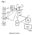
- Figure 1 shows the structure of a radio communication system in which the method according to the invention is applicable. It consists of a plurality of mobile switching centers MSC, which are networked with each other or provide access to a fixed network PSTN. Furthermore, these mobile switching centers MSC are each connected to at least one base station controller BSC. Each base station controller BSC in turn allows a connection to at least one base station BS. Such a base station BS can establish a communication link to subscriber stations MS via a radio interface. For this purpose, at least some of the base stations BS are equipped with antenna devices AE, which have a plurality of antenna elements (A 1 -A A M ).
- FIG. 1 shows, by way of example, connections V1, V2,..., Vk for transmitting useful information and signaling information between subscriber stations MS1, MS2,..., MSk,... MSn and a base station BS.
- connections V1, V2,..., Vk for transmitting useful information and signaling information between subscriber stations MS1, MS2,..., MSk,... MSn and a base station BS.
- Different transmission paths of the connection V k are symbolized by arrows between the base station BS and the subscriber station MSk.
- An Operations and Maintenance Center OMC implements control and maintenance functions for the mobile network or parts of it.
- the functionality of this structure is transferable to other radio communication systems in which the invention can be used, in particular for subscriber access networks with a wireless subscriber line.
- FIG. 2 shows schematically the structure of the receiving part of a base station BS for carrying out the method according to the invention.
- the base station BS comprises an antenna device AE with a plurality of antenna elements A 1 , A 2 ,..., A M , which receive the uplink signal transmitted by the subscriber station MSk.
- the baseband converted receive signal of each antenna element is fed to a so-called Rake Searcher RS, which serves to measure propagation time differences of contributions of the uplink signal that have reached the antenna element on different propagation paths.
- the receive signal is also applied to a rake amplifier RA which comprises a plurality of rake fingers, three of which are shown in the figure, and each having a delay DEL and a despreader EE.
- the delay elements DEL delay the received signal in each case by a delay value ⁇ 1 , ⁇ 2 , ⁇ 3 , .... supplied by the Rake-Searcher RS.
- the despreader descramblers EE deliver a sequence of estimated symbols at their outputs, the results of the estimation may be different for each descrambler due to different phase angles of the downlink signal Entscrambling- and spreading code in the individual fingers of the rake amplifier.
- the symbol sequences provided by despreader descramblers EE form input signals of a combiner C, which the Variety of symbol sequences to an estimated symbol sequence assembles.
- the symbol sequences supplied by the despreading descramblers EE also contain the results of the estimation of training sequences which are broadcast by the subscriber stations MS1, MS2,..., MSk,..., MSn and which are quasi identical for the individual subscriber stations. orthogonal and characteristic.
- a signal processor SP is used to compare the results of the estimation of these training sequences with the base station known, actually transmitted by the subscriber stations symbols of the training sequences. By carrying out this comparison individually for each finger of the rake amplifier RA, ie for each delay or tap found by the rake-searcher RS, the impulse response of the transmission channel between the base station BS and the subscriber station MSk can be determined for each antenna element A 1 , A 2 , ..., A M and each tap are obtained individually.
- the signal processor SP adds for each tap the impulse responses of all antenna elements A 1 , ..., A M in the manner known, for example, from the cited DE 198 03 188 to a spatial covariance matrix R xx together.
- the evaluation of the covariance matrices R xx thus obtained by a control unit SE will be explained in more detail with reference to the diagram of FIG.
- the control unit SE initially forms an average value R xx over a large number of successively generated covariance matrices R xx to average out the effects of fast fading on the channel.
- fluctuation ranges for coefficients of the covariance matrices are determined (section S1, channel estimation). If these fluctuation margins are smaller than a suitably set limit value, ie the transmission channel does not change over time, this is an indication that the subscriber stations and also reflectors to which the uplink signal radiated by the subscriber station travels on its way to Base station is reflected, do not move. In such a case, the fast fading evaluation is not possible, and the shape of the covariance matrix does not allow conclusions about channel characteristics such as origin direction of the uplink signal, average attenuation, etc.
- This result is forwarded by the control unit SE to the transmitting section TX (FIG. 2) of the base station in order to cause an undirected transmission of the downlink signal (step S2).
- the control unit SE decides whether a direction of origin can be assigned to the received uplink signal. This possibility exists whenever there is a phase relationship between uplink signals received from different antenna elements of the base station, ie, when the covariance matrix R xx has non-disappearing off-diagonal components.
- the information about the origin direction of the uplink signal is in the eigenvectors of the covariance matrix R xx included; their coefficients indicate the relative phase angles with which a coherent uplink signal reaches the individual antenna elements.
- step S3 If a phase relationship exists between the uplink signals arriving at the individual antenna elements, in other words, if the channel is spatially correlated (step S3), and the control unit SE does so at the non-diagonal elements of the covariance matrix R xx detects, it determines in the sequence, whether a direct transmission connection between the base station and the subscriber station exists.
- a direct transmission path is always the shortest possible transmission path, therefore, among several contributions of the received uplink signal offset in time, only the earliest one can correspond to a direct transmission connection.
- control unit SE recognizes that there is a direct transmission path (step S4), and causes directional broadcasting of the downlink signal in the origin direction corresponding to the direct transmission path (step S5). If uplink and downlink use the same frequencies, it is sufficient for such beam shaping of the downlink beam to weight the contributions of the downlink signal to be radiated by the individual antenna elements with the coefficients of the eigenvector w (k) corresponding to this transmission path.
- the phases of the components of this eigenvector can be converted into phase differences, as is familiar to one skilled in the art, and these can again be converted into phase differences using the downlink frequency, so as to produce a weighting vector w (k) for beamforming To get downlink beam.
- step S6 If no direct transmission connection between the base station and the subscriber station is detected (step S6), ie the existing transmission paths contain at least one reflection, then there is a risk that one of these transmission paths will fail for a short time due to fast fading.
- the control unit SE not only determines a single eigenvector w (k) of the covariance matrix in such a case, but selects from the totality of the eigenvectors of the covariance matrix those having the largest eigenvalues. These eigenvectors correspond to the transmission paths with the lowest attenuation.
- step S7 By simultaneously broadcasting the downlink signal in the directions of origin of at least two of these transmission paths (step S7), the risk of transmission interruption is minimized.
- the control unit SE in the case of non-existence of a direct transmission path additionally a differentiation depending on from the speed with which the subscriber station moved relative to the base station. If that speed is very large, this leads to an inherent Time diversity because the subscriber station is in places involving a destructive interference of the downlink signal takes place, in each case only very briefly stops, and thereby Conditional receive interruptions due to error correction can be compensated.
- the control unit is able to the speed of movement of the subscriber station on the basis of Estimate speed with which the eigenvectors change the averaged spatial covariance matrix.
- step S8 is the downlink beam on multiple transmission paths simultaneously radiated (step S7) when the speed of Subscriber station is larger (step S9), is only in the direction the transmission path with the lowest attenuation radiated (Step S5).
- Step S10 If the channel turns out to be spatially uncorrelated (Step S10), is through to the averaged spatial covariance supported beamforming no improvement in transmission quality to reach.
- the control unit according to a simpler embodiment of Process the broadcast of the downlink signal using one or more diversity techniques such as OTD, TSTD or STD (step S11).
- step S11 it is additionally possible to distinguish between fast and slow moving subscriber stations, whereby the use of said diversity techniques step S11) remains limited to fast moving subscriber stations (step S13).
- step S12 in which the characteristics of the transmission channel also change slowly, as in the case of the invariable channel already discussed above, the transmission of the downlink signal using weighting vectors optimized by feedback from the subscriber station (step S14) is preferred.
- step S14 directed emission of the downlink signal is also possible in those situations where the uplink signal has a direction of origin at any time, or at least most of the time, but this origin varies so rapidly that it is in the averaged covariance matrix R xx is no longer recognizable.
Landscapes
- Engineering & Computer Science (AREA)
- Computer Networks & Wireless Communication (AREA)
- Signal Processing (AREA)
- Mobile Radio Communication Systems (AREA)
- Radio Transmission System (AREA)
Claims (9)
- Procédé pour la commande du faisceau de liaison descendante dans un système de radiocommunication comprenant un dispositif d'antenne (AE) comprenant plusieurs éléments d'antenne, caractérisé par les étapes suivantesen cas de non-existence d'une corrélation de phases, émission non dirigée du signal descendant sous la forme de plusieurs apports générés avec l'utilisation d'au moins une technique de diversité.a) analyse d'un signal ascendant reçu d'un émetteur (MSK) au niveau de l'existence de corrélations de phases entre des parties du signal ascendant reçues de différents éléments d'antenne du dispositif d'antenne (AE), etb) en cas d'existence d'une corrélation de phases, attribution d'au moins une direction d'origine au signal ascendant et émission dirigée du signal descendant dans la direction d'origine, et
- Procédé selon la revendication 1, caractérisé en ce que, avec un canal constant, le signal descendant est émis de façon non dirigée sous la forme de plusieurs apports générés avec l'utilisation d'au moins une technique de diversité.
- Procédé selon la revendication 1 ou 2, caractérisé en ce que la technique de diversité est choisie parmi la diversité de temps, la diversité d'antenne, la diversité de code, la diversité de fréquence.
- Procédé selon la revendication 2 et la revendication 3, caractérisé en ce que, avec un canal constant et/ou variable lentement, une information concernant des puissances d'émission relatives des apports, à utiliser dans le signal descendant, est transmise dans le signal ascendant.
- Procédé selon l'une quelconque des revendications précédentes, caractérisé en ce que, en cas d'existence d'une corrélation de phases et d'existence d'un trajet de transmission direct pour le signal ascendant, la direction d'origine du signal ascendant est déterminée et le signal descendant est envoyé exclusivement dans la direction de l'un signal ascendant.
- Procédé selon la revendication 5, caractérisé en ce que l'existence d'un trajet de transmission direct est constatée lorsque l'amplitude de l'apport la plus précoce dans le temps du signal ascendant est non variable dans le temps.
- Procédé selon l'une quelconque des revendications précédentes, caractérisé en ce que, en cas d'existence d'une corrélation de phases et de non-existence d'un trajet de transmission direct pour le signal ascendant, plusieurs directions d'origine du signal ascendant sont déterminées et le signal descendant est envoyé orienté respectivement dans plusieurs directions.
- Procédé selon la revendication 7, caractérisé en ce que la vitesse de variation des directions d'origine est enregistrée et en ce que le signal descendant est envoyé uniquement dans la direction d'origine de l'apport le plus important au signal ascendant, lorsque la vitesse dépasse une valeur limite.
- Procédé selon l'une quelconque des revendications précédentes, caractérisé en ce que, lors de l'analyse du signal ascendant au niveau de l'existence de corrélations de phases, une matrice de covariance moyenne des parties du signal ascendant est générée et la non-existence de corrélations de phases est supposée lorsque la matrice de covariance moyenne est sensiblement diagonale.
Applications Claiming Priority (3)
| Application Number | Priority Date | Filing Date | Title |
|---|---|---|---|
| DE10025987A DE10025987C2 (de) | 2000-05-25 | 2000-05-25 | Verfahren zum Steuern der Downlink-Strahlformung |
| DE10025987 | 2000-05-25 | ||
| PCT/DE2001/001970 WO2001091325A1 (fr) | 2000-05-25 | 2001-05-22 | Procede de commande de la formation de faisceau de liaison descendante |
Publications (2)
| Publication Number | Publication Date |
|---|---|
| EP1284055A1 EP1284055A1 (fr) | 2003-02-19 |
| EP1284055B1 true EP1284055B1 (fr) | 2005-08-17 |
Family
ID=7643575
Family Applications (1)
| Application Number | Title | Priority Date | Filing Date |
|---|---|---|---|
| EP01947170A Expired - Lifetime EP1284055B1 (fr) | 2000-05-25 | 2001-05-22 | Procede de commande de la formation de faisceau de liaison descendante |
Country Status (6)
| Country | Link |
|---|---|
| US (1) | US7039368B2 (fr) |
| EP (1) | EP1284055B1 (fr) |
| KR (1) | KR100767129B1 (fr) |
| AU (1) | AU2001268940A1 (fr) |
| DE (2) | DE10025987C2 (fr) |
| WO (1) | WO2001091325A1 (fr) |
Families Citing this family (13)
| Publication number | Priority date | Publication date | Assignee | Title |
|---|---|---|---|---|
| RU2237379C2 (ru) | 2002-02-08 | 2004-09-27 | Самсунг Электроникс | Способ формирования диаграммы направленности адаптивной антенной решетки базовой станции и устройство для его реализации (варианты) |
| US7372911B1 (en) * | 2002-06-28 | 2008-05-13 | Arraycomm, Llc | Beam forming and transmit diversity in a multiple array radio communications system |
| US20040008648A1 (en) * | 2002-07-11 | 2004-01-15 | Schmidl Timothy M. | Diversity decisions for downlink antenna transmission |
| JP4289854B2 (ja) * | 2002-09-20 | 2009-07-01 | 京セラ株式会社 | 無線基地装置、移動端末装置、参照信号制御方法および参照信号制御プログラム |
| US7057555B2 (en) * | 2002-11-27 | 2006-06-06 | Cisco Technology, Inc. | Wireless LAN with distributed access points for space management |
| FI20030777A0 (fi) * | 2003-05-22 | 2003-05-22 | Nokia Corp | Lähetysdiversiteetin kertaluvun ja lähetyshaarojen määritys |
| US7054664B2 (en) * | 2003-10-30 | 2006-05-30 | Lucent Technologies Inc. | Method and apparatus for providing user specific downlink beamforming in a fixed beam network |
| US20080267142A1 (en) * | 2004-06-18 | 2008-10-30 | Stellaris Ltd. | Distributed Antenna Wlan Access-Point System and Method |
| KR20070046832A (ko) | 2004-07-30 | 2007-05-03 | 마쓰시다 일렉트릭 인더스트리얼 컴패니 리미티드 | 무선 통신 장치 및 무선 통신 방법 |
| WO2009083680A1 (fr) * | 2008-01-03 | 2009-07-09 | France Telecom | Communication par voie de retour d'un terminal vers un emetteur pour reduire notamment une interference entre faisceaux issus de l'emetteur |
| JP4730677B1 (ja) * | 2011-01-27 | 2011-07-20 | 日本電気株式会社 | 情報処理装置及び情報処理方法並びに情報処理プログラム |
| US10587329B2 (en) * | 2017-09-22 | 2020-03-10 | Qualcomm Incorporated | Transmit antenna diversity in radio front end architectures |
| EP4084358B1 (fr) * | 2021-04-29 | 2025-05-14 | Nxp B.V. | Unité de récepteur sans fil, circuit de correcteur de phase spatiale pour modulation d'amplitude correcteur et procédé associé |
Family Cites Families (11)
| Publication number | Priority date | Publication date | Assignee | Title |
|---|---|---|---|---|
| SE514000C2 (sv) * | 1992-04-29 | 2000-12-11 | Telia Ab | Förfarande och anordning för att minska fädningen mellan basstation och mobila enheter |
| JPH08195703A (ja) * | 1995-01-17 | 1996-07-30 | Toshiba Corp | 無線通信装置 |
| IT1285217B1 (it) * | 1996-07-04 | 1998-06-03 | Italtel Spa | Metodo per la selezione automatica di un fascio tra quelli formati da un'antenna multifascio,in particolare per sistemi radiomobili |
| US6122260A (en) | 1996-12-16 | 2000-09-19 | Civil Telecommunications, Inc. | Smart antenna CDMA wireless communication system |
| FI106669B (fi) * | 1997-08-20 | 2001-03-15 | Nokia Networks Oy | Lähetysmenetelmä ja radiojärjestelmä |
| FI980035A7 (fi) * | 1998-01-09 | 1999-07-10 | Nokia Corp | Menetelmä antennikeilan suuntaamiseksi ja lähetinvastaanotin |
| DE19803188B4 (de) * | 1998-01-28 | 2006-04-20 | Siemens Ag | Verfahren und Basisstation zur Datenübertragung in einem Funk-Kommunikationssystem |
| US6989797B2 (en) * | 1998-09-21 | 2006-01-24 | Ipr Licensing, Inc. | Adaptive antenna for use in wireless communication systems |
| JP3641961B2 (ja) * | 1999-02-01 | 2005-04-27 | 株式会社日立製作所 | アダプティブアレイアンテナを使用した無線通信装置 |
| US6489923B1 (en) * | 1999-09-16 | 2002-12-03 | Nortel Networks Limited | Position location method and apparatus for a mobile telecommunications system |
| US7039441B1 (en) * | 1999-10-19 | 2006-05-02 | Kathrein-Werke Kg | High speed fixed wireless voice/data systems and methods |
-
2000
- 2000-05-25 DE DE10025987A patent/DE10025987C2/de not_active Expired - Fee Related
-
2001
- 2001-05-22 EP EP01947170A patent/EP1284055B1/fr not_active Expired - Lifetime
- 2001-05-22 AU AU2001268940A patent/AU2001268940A1/en not_active Abandoned
- 2001-05-22 DE DE50107123T patent/DE50107123D1/de not_active Expired - Fee Related
- 2001-05-22 WO PCT/DE2001/001970 patent/WO2001091325A1/fr not_active Ceased
- 2001-05-22 KR KR1020027015808A patent/KR100767129B1/ko not_active Expired - Fee Related
- 2001-05-22 US US10/296,097 patent/US7039368B2/en not_active Expired - Fee Related
Also Published As
| Publication number | Publication date |
|---|---|
| DE10025987A1 (de) | 2001-12-20 |
| KR20030003757A (ko) | 2003-01-10 |
| KR100767129B1 (ko) | 2007-10-15 |
| DE10025987C2 (de) | 2002-04-04 |
| WO2001091325A1 (fr) | 2001-11-29 |
| EP1284055A1 (fr) | 2003-02-19 |
| US20040082299A1 (en) | 2004-04-29 |
| AU2001268940A1 (en) | 2001-12-03 |
| DE50107123D1 (de) | 2005-09-22 |
| US7039368B2 (en) | 2006-05-02 |
Similar Documents
| Publication | Publication Date | Title |
|---|---|---|
| DE10026077B4 (de) | Strahlformungsverfahren | |
| EP1297639B1 (fr) | Procede de formation de faisceau | |
| DE60029012T2 (de) | Verfahren und vorrichtung für sende-diversity | |
| DE60316385T2 (de) | Vorrichtung und Verfahren zur Datenübertragung mit Sendeantennendiversität in einem Kommunikationssystem mit Paketdiensten | |
| DE19803188B4 (de) | Verfahren und Basisstation zur Datenübertragung in einem Funk-Kommunikationssystem | |
| DE69900645T2 (de) | Sende-Diversity Verfahren und System mit Phasenregelung für Funkübertragungssysteme | |
| DE60021772T2 (de) | Verfahren und vorrichtung zur übertragung mit mehreren antennen | |
| DE602004012136T2 (de) | Verfahren und vorrichtung für ein mehrstrahl-antennensystem | |
| DE60306430T2 (de) | Vorrichtung und verfahren zur verwendung von strahlformung und sende-diversität mit geschlossenem regelkreis in einem mehrfachstrahl-antennensystem | |
| EP1402657B1 (fr) | Procede de traitement de signaux adaptatif dans un systeme a entrees multiples et sorties multiples | |
| DE69630616T2 (de) | Winkeldiversitätsverfahren und basisstationsvorrichtung | |
| DE10051144C2 (de) | Verfahren zur Verbesserung einer Kanalabschätzung in einem Funk-Kommunikationssystem | |
| EP1284055B1 (fr) | Procede de commande de la formation de faisceau de liaison descendante | |
| DE60118280T2 (de) | Funkanlage, die zur Echtzeitveränderung der Antennenrichtwirkung fähig ist, und für die Funkanlage verwendete Dopplerfrequenzschätzschaltung | |
| DE60128999T2 (de) | Diversitätsübertragung | |
| EP1224749B1 (fr) | Formation d'un faisceau dans un systeme de communication radio | |
| DE10026076C2 (de) | Verfahren und Vorrichtung zum Auswerten eines Uplink-Funksignals | |
| DE10032427A1 (de) | Verfahren und Vorrichtung zum Auswerten eines Funksignals | |
| DE10025287B4 (de) | Verfahren und Kommunikationssystem zur Schätzung einer Störungs-Kovarianzmatrix für die Abwärtsverbindung in zellularen Mobilfunknetzen mit adaptiven Antennen | |
| EP1284053B1 (fr) | Procede de formation de faisceau destine au sens descendant dans un systeme de communication radio | |
| EP1352483B1 (fr) | Procede de transmission d'une information de retroaction dans un systeme de communication radio, et stations pour un systeme de communication radio | |
| DE10058336B4 (de) | Verfahren zur Strahlformung in Systemen mit Gruppenantennen an Sende- und Empfangsstationen | |
| EP1383250B1 (fr) | Procédé d'adaptation dynamique de la formation de faisceaux dans un système de communication radio | |
| EP1352484B1 (fr) | Procede de transfert en retour dans un systeme de radiocommunication, et stations pour un systeme de radiocommunication | |
| DE102004027290A1 (de) | Empfang von Signalen in einem Funkkommunikationssystem mittels zweier Richtcharakteristiken |
Legal Events
| Date | Code | Title | Description |
|---|---|---|---|
| PUAI | Public reference made under article 153(3) epc to a published international application that has entered the european phase |
Free format text: ORIGINAL CODE: 0009012 |
|
| 17P | Request for examination filed |
Effective date: 20021105 |
|
| AK | Designated contracting states |
Designated state(s): AT BE CH CY DE DK ES FI FR GB GR IE IT LI LU MC NL PT SE TR |
|
| AX | Request for extension of the european patent |
Extension state: AL LT LV MK RO SI |
|
| RBV | Designated contracting states (corrected) |
Designated state(s): DE ES FR GB IT TR |
|
| GRAP | Despatch of communication of intention to grant a patent |
Free format text: ORIGINAL CODE: EPIDOSNIGR1 |
|
| GRAS | Grant fee paid |
Free format text: ORIGINAL CODE: EPIDOSNIGR3 |
|
| GRAA | (expected) grant |
Free format text: ORIGINAL CODE: 0009210 |
|
| AK | Designated contracting states |
Kind code of ref document: B1 Designated state(s): DE ES FR GB IT TR |
|
| PG25 | Lapsed in a contracting state [announced via postgrant information from national office to epo] |
Ref country code: TR Free format text: LAPSE BECAUSE OF FAILURE TO SUBMIT A TRANSLATION OF THE DESCRIPTION OR TO PAY THE FEE WITHIN THE PRESCRIBED TIME-LIMIT Effective date: 20050817 |
|
| REG | Reference to a national code |
Ref country code: GB Ref legal event code: FG4D Free format text: NOT ENGLISH |
|
| GBT | Gb: translation of ep patent filed (gb section 77(6)(a)/1977) |
Effective date: 20050818 |
|
| REF | Corresponds to: |
Ref document number: 50107123 Country of ref document: DE Date of ref document: 20050922 Kind code of ref document: P |
|
| PG25 | Lapsed in a contracting state [announced via postgrant information from national office to epo] |
Ref country code: ES Free format text: LAPSE BECAUSE OF FAILURE TO SUBMIT A TRANSLATION OF THE DESCRIPTION OR TO PAY THE FEE WITHIN THE PRESCRIBED TIME-LIMIT Effective date: 20051128 |
|
| PLBE | No opposition filed within time limit |
Free format text: ORIGINAL CODE: 0009261 |
|
| STAA | Information on the status of an ep patent application or granted ep patent |
Free format text: STATUS: NO OPPOSITION FILED WITHIN TIME LIMIT |
|
| 26N | No opposition filed |
Effective date: 20060518 |
|
| PG25 | Lapsed in a contracting state [announced via postgrant information from national office to epo] |
Ref country code: FR Free format text: LAPSE BECAUSE OF FAILURE TO SUBMIT A TRANSLATION OF THE DESCRIPTION OR TO PAY THE FEE WITHIN THE PRESCRIBED TIME-LIMIT Effective date: 20060818 |
|
| EN | Fr: translation not filed | ||
| PGFP | Annual fee paid to national office [announced via postgrant information from national office to epo] |
Ref country code: DE Payment date: 20080523 Year of fee payment: 8 |
|
| PG25 | Lapsed in a contracting state [announced via postgrant information from national office to epo] |
Ref country code: FR Free format text: LAPSE BECAUSE OF FAILURE TO SUBMIT A TRANSLATION OF THE DESCRIPTION OR TO PAY THE FEE WITHIN THE PRESCRIBED TIME-LIMIT Effective date: 20050817 |
|
| REG | Reference to a national code |
Ref country code: GB Ref legal event code: 732E Free format text: REGISTERED BETWEEN 20090205 AND 20090211 |
|
| PG25 | Lapsed in a contracting state [announced via postgrant information from national office to epo] |
Ref country code: DE Free format text: LAPSE BECAUSE OF NON-PAYMENT OF DUE FEES Effective date: 20091201 |
|
| PGFP | Annual fee paid to national office [announced via postgrant information from national office to epo] |
Ref country code: IT Payment date: 20100522 Year of fee payment: 10 |
|
| PG25 | Lapsed in a contracting state [announced via postgrant information from national office to epo] |
Ref country code: IT Free format text: LAPSE BECAUSE OF NON-PAYMENT OF DUE FEES Effective date: 20110522 |
|
| PGFP | Annual fee paid to national office [announced via postgrant information from national office to epo] |
Ref country code: GB Payment date: 20140521 Year of fee payment: 14 |
|
| GBPC | Gb: european patent ceased through non-payment of renewal fee |
Effective date: 20150522 |
|
| PG25 | Lapsed in a contracting state [announced via postgrant information from national office to epo] |
Ref country code: GB Free format text: LAPSE BECAUSE OF NON-PAYMENT OF DUE FEES Effective date: 20150522 |