EP1402657B1 - Procede de traitement de signaux adaptatif dans un systeme a entrees multiples et sorties multiples - Google Patents
Procede de traitement de signaux adaptatif dans un systeme a entrees multiples et sorties multiples Download PDFInfo
- Publication number
- EP1402657B1 EP1402657B1 EP02758084A EP02758084A EP1402657B1 EP 1402657 B1 EP1402657 B1 EP 1402657B1 EP 02758084 A EP02758084 A EP 02758084A EP 02758084 A EP02758084 A EP 02758084A EP 1402657 B1 EP1402657 B1 EP 1402657B1
- Authority
- EP
- European Patent Office
- Prior art keywords
- transmission
- channel
- matrix
- signal processing
- signals
- Prior art date
- Legal status (The legal status is an assumption and is not a legal conclusion. Google has not performed a legal analysis and makes no representation as to the accuracy of the status listed.)
- Expired - Lifetime
Links
Images




Classifications
-
- H—ELECTRICITY
- H04—ELECTRIC COMMUNICATION TECHNIQUE
- H04B—TRANSMISSION
- H04B7/00—Radio transmission systems, i.e. using radiation field
- H04B7/02—Diversity systems; Multi-antenna system, i.e. transmission or reception using multiple antennas
- H04B7/04—Diversity systems; Multi-antenna system, i.e. transmission or reception using multiple antennas using two or more spaced independent antennas
- H04B7/0413—MIMO systems
-
- H—ELECTRICITY
- H04—ELECTRIC COMMUNICATION TECHNIQUE
- H04B—TRANSMISSION
- H04B7/00—Radio transmission systems, i.e. using radiation field
- H04B7/02—Diversity systems; Multi-antenna system, i.e. transmission or reception using multiple antennas
- H04B7/04—Diversity systems; Multi-antenna system, i.e. transmission or reception using multiple antennas using two or more spaced independent antennas
- H04B7/06—Diversity systems; Multi-antenna system, i.e. transmission or reception using multiple antennas using two or more spaced independent antennas at the transmitting station
- H04B7/0613—Diversity systems; Multi-antenna system, i.e. transmission or reception using multiple antennas using two or more spaced independent antennas at the transmitting station using simultaneous transmission
- H04B7/0615—Diversity systems; Multi-antenna system, i.e. transmission or reception using multiple antennas using two or more spaced independent antennas at the transmitting station using simultaneous transmission of weighted versions of same signal
-
- H—ELECTRICITY
- H04—ELECTRIC COMMUNICATION TECHNIQUE
- H04B—TRANSMISSION
- H04B7/00—Radio transmission systems, i.e. using radiation field
- H04B7/02—Diversity systems; Multi-antenna system, i.e. transmission or reception using multiple antennas
- H04B7/04—Diversity systems; Multi-antenna system, i.e. transmission or reception using multiple antennas using two or more spaced independent antennas
- H04B7/08—Diversity systems; Multi-antenna system, i.e. transmission or reception using multiple antennas using two or more spaced independent antennas at the receiving station
- H04B7/0837—Diversity systems; Multi-antenna system, i.e. transmission or reception using multiple antennas using two or more spaced independent antennas at the receiving station using pre-detection combining
- H04B7/0842—Weighted combining
- H04B7/0848—Joint weighting
- H04B7/0854—Joint weighting using error minimizing algorithms, e.g. minimum mean squared error [MMSE], "cross-correlation" or matrix inversion
-
- H—ELECTRICITY
- H04—ELECTRIC COMMUNICATION TECHNIQUE
- H04B—TRANSMISSION
- H04B7/00—Radio transmission systems, i.e. using radiation field
- H04B7/02—Diversity systems; Multi-antenna system, i.e. transmission or reception using multiple antennas
- H04B7/04—Diversity systems; Multi-antenna system, i.e. transmission or reception using multiple antennas using two or more spaced independent antennas
- H04B7/0413—MIMO systems
- H04B7/0426—Power distribution
- H04B7/0434—Power distribution using multiple eigenmodes
- H04B7/0443—Power distribution using multiple eigenmodes utilizing "waterfilling" technique
Definitions
- the invention relates to an adaptive signal processing method for a bidirectional radio transmission of digital data streams in up and down Downlink direction via a MIMO channel with n antennas on one side and m antennas on the other side of the channel and with a transmitting side Signal preprocessing of the transmission signals x and a reception-side signal post-processing the received signals y, both on an estimate of the complex channel matrix based, and on a MIMO system with at least an uplink transmitting station with n antennas, a downlink transmitting station with m antennas and a signal processing unit at least in the m Antenna equipped station for performing the adaptive signal processing method.
- Modern mobile communication systems are expected to be in use Narrow frequency bands High bit rate data at low transmission power transmitted as error-free as possible. This ideal is the random nature the radio channel whose amplitude and phase response is temporally, vary greatly locally and depending on the carrier frequency (fading). Radio channels can be statistically transmitted through a Rayleigh (without line of sight) or Rice distribution (with line of sight).
- the invention relates to an adaptive transmission method on the basis of multi-element antennas at a mobile station on one side and one Base station on the other side of the channel, between which a bidirectional Radio operation takes place so that both sides act as sender and receiver may occur.
- MIMO multiple-input-multiple-output
- Such multiple-input-multiple-output (MIMO) systems are being investigated worldwide, so that the per 1 Hz bandwidth. transferable amount of data (“spectral efficiency”) are significantly increased can. This is done by sending multiple streams simultaneously same frequency band (co-channel operation) achieved.
- MIMO systems play an important role in radio transmission since Foschini has shown that it can significantly improve the spectral efficiency, ie the use of the scarce resource "bandwidth" [1].
- H here is called the "channel matrix” in which the Amplitude and phase values of the individual channels between each possible Pair of transmit and receive antennas ("data signal paths").
- the vector n describes the noise at the individual receiving antennas.
- the transmitted data signals can at the receiving end by a suitable Signal processing are separated again.
- Separation of the data signals is the knowledge of the channel matrix H required to be achieved in practice by an advance and in periodically repeated estimation of the channel matrix H on the Based on reference signals can [1].
- the recursive signal processing method eg Turbo-BLAST [3] or BLAST in combination with MMSE detection [4] ). Weak points are the time-consuming recursive signal processing, which makes a real-time transmission at high data rates difficult, as well as the nonlinear decisions made within the recursion, which can lead to further erroneous decisions on the later detected data streams in the event of an error.
- a channel may be considered “flat” if the complex valued channel coefficient changes only slightly as a function of the frequency in the transmission band. This is the case only for narrow-band transmission systems, where the propagation delay of the radio signals between transmitter and receiver is smaller than the symbol duration. Otherwise, the channel is frequency-selective, and it also requires a temporal equalization of the signals. In the work by Wong et al., 2000 [6] , the common spatial-temporal equalization for a MIMO system in frequency-selective channels is investigated.
- the data to be transmitted is multiplied by a transmission matrix T and the data to be received by a reception matrix R.
- a common signal model is used in which the actually necessary convolution of the transmission signal with the matrix channel impulse response is reformulated as multiplication by a Töplitz matrix.
- the structure of the matrices R and T is derived which minimizes the signal-to-interference and noise ratio at the detector (minimum mean square error solution, MMSE).
- MMSE minimum mean square error solution
- Task complex for the present invention is therefore the well-known Adaptive signal processing method of the type mentioned in one MIMO channel so that an optimization of the bit error rate in the Sense of a significant reduction is achieved. It should be the inventive method show a basic system solution. At the same time as little as possible with the inventive method Transmissions and transmissions in real time can be achieved. In the Implementation into a concrete MIMO system should be ensured by the improved procedures achieved efficiency simple and therefore easy manageable and cost-effective implementation possibilities arise.
- the solution to this problem complex is in the present invention basically by the characterizing features of the main claim for an adaptive signal processing method in a MIMO channel of the generic type Kind and by the characteristic features of the sibling Claim for a MIMO system of the generic type for characterized advantageous embodiment of the method according to the invention.
- Preferred embodiments of the invention are the respective subordinate ones Claims to be taken.
- the adaptive signal processing method according to the invention is complete. Redundancy and feedback free. It does not work on the principle of recursive error compensation, but avoids the occurrence of errors in advance.
- the method is characterized by a consistently linear Signal processing in particular in the upward sending direction with a very low signal processing effort.
- the signal-to-noise power ratio is signal preprocessed at the transmitter in all individual channels of the MIMO transmission channel made equal. This one reaches over a pre-determined Number of single channels one transmission with equal quality for all Channels. One can therefore the same symbol rate in all single channels use and use the same modulation method.
- the present invention provides for an innovative, wireless Communication system good transmission characteristics and is relative to the efficiency in the practical implementation in the area of the optimum, since the Effort is relatively low.
- the data signals to be sent can be optimally transmitted to the radio transmission channel bessenkoppeit.
- the noise characteristics at the receiver remain of the signal reconstruction largely untouched and you reach already at low transmission power comparatively low bit error rates, which otherwise only in the wired transmission or in directed radio communications with Visual connection is possible.
- the MIMO system for implementing the Signal processing method according to the invention comes without Viewing connection off.
- the proposed transmitter and receiver side Signal processing has a linear-algebraic structure, which is a simple, real-time capable implementation even at high data rates.
- the adaptive signal processing method of the invention is based on a linear decomposition of the channel matrix. For linear decomposition of matrices, various methods of mathematics are well known and well established.
- the singular values are the roots of the eigenvalues of the channel matrix H.
- the number of eigenvalues corresponds to the number of parallel (virtual) individual channels in the MIMO channel.
- the size of the eigenvalues is a measure of the power transfer in a single channel.
- the maximum number of parallel individual channels corresponds to the rank of the channel matrix, which is given by the smaller number.
- the singular values are continuously distributed over a broad band, which means that within certain limits there are small and large singular values.
- the signal vector x is multiplied by the matrix V H. This corresponds to a rotation or illustratively a projection onto the directions of the parallel (virtual) individual channels.
- V H the matrix of the signal vector x
- each data signal sent by one antenna is distributed to all parallel individual channels.
- the diagonal matrix D the signal mixture projected onto each individual channel is now stretched by the value of the associated singular value.
- the multiplication by the matrix U which is not even square due to the inequality of the number of antennas between both channel sides (n ⁇ m), causes an image in the space of the receiving antennas.
- the previously stretched signals of the n vertical individual channels are thereby projected onto m orthogonal vectors in the space of the receiving antennas.
- H -1 ⁇ H provides the unit matrix.
- the diagonal matrix D -1 contains the inverse singular values which, like the singular values themselves, are distributed over a broad band. It can also be seen that in particular the smallest singular value, which occasionally can also be close to zero, has a decisive influence on the noise remaining in equation (2) and correspondingly increased by multiplication with the inverse singular values after the reconstruction of the transmitted data signals.
- the singular value decomposition is real-time capable, that is, it can also be computed for larger channel matrices H with modem microprocessors in a time that is short compared to the temporal variation of the channel.
- the two types of channel inversion in the uplink according to equations (5) and (5a) differ in the way the data is distributed to the main axes in the transmission room. In the first case, the channel is inverted, but each data stream is transmitted across all major axes in the signal space. In the second case, each data stream is transformed to a main axis in the signal space and transmitted. From the signaling, no difference in the performance of both variants can be seen, but it can be assumed that the first variant is somewhat more robust with respect to channel estimation errors, because the data is spread over all main axes.
- Each transmitting antenna thus transmits another linear combination of the data signals x into the MIMO transmission channel, that is, the transmitting vector x is replaced in equation (1) by the modified transmitting vector x * according to equation (5).
- the following explanations serve to illustrate this transmitter-side signal pre-processing in the up-send direction.
- the signal preprocessing ensures that a data signal stream is now transmitted via all n antennas in such a way that it lies exactly in the projection direction of a single channel. This procedure is analogous for all parallel individual channels.
- each data signal stream then experiences the extension by the reciprocal of the singular value associated with the single channel, that is, all the data signal streams would be transmitted differently without signal preprocessing.
- the transmission power increases due to the transmitter-side signal processing in the uplink and downlink by the factor n / (nm).
- the noise is additionally multiplied by the matrices V and U H. This reduces the dimension of the randomly distributed random noise vector from m to n, that is, on average, the vector becomes shorter. If, instead of the received power as above, the transmission power is used as the evaluation criterion for the signal processing methods, then the bit error rate of channel inversion in the upward direction at the same number of antennas is approximately comparable to the bit error rate of the known V-BLAST method (see Figure 8).
- channel inversion requires only one linear matrix-vector multiplication at the transmitter and the receiver, while the V-BLAST method has to perform several matrix-vector multiplications one after the other at the receiver.
- channel inversion requires significantly longer pilot sequences than the V-BLAST method, which seems feasible only for higher data rates.
- the transmission signal is merely multiplied by a right-sided pseudoinverse of the channel matrix. If the channel estimation in the uplink transmission direction and the downlink transmission data are at the same frequency and the channel matrix is uplinked by H, then H T is the channel matrix in the downlink direction, ie in equation (1) H is transposed by the transposed H T replaced. This follows from the assumption of the so-called "reciprocity" of the radio channel. If one forms any pair from one antenna on both sides of the MIMO channel, then the associated up and down transmission distances in a time window have the same channel properties, as long as no temporal change has occurred.
- the concept of signal processing according to the present invention can be In practice, particularly easy to implement, because you have the data signal vector in the upstream transmitter direction at the transmitter and receiver side only in each case multiply by a matrix. In the downward sending direction, the Data signal vector only multiplied by a matrix on the transmitter side.
- the linear signal processing method according to Invention is much better for high-speed real-time transmission Data signal rates are suitable In addition, you can have the same reception power realize significantly lower bit error rates.
- one side of the MIMO transmission channel has to use at least one more antenna than on the other side for reasons of limited transmission power. More suitable, however, is the addition of additional antennas in the downlink transmitter to further reduce transmitter dynamics.
- the second requirement is that a relatively accurate channel estimation is needed.
- the dispersion of the estimation error should be smaller by about a factor of 3 than in the known BLAST method. In order to achieve the lowest possible bit error rates, therefore, with a possible implementation of the channel estimation, for example with orthogonal pilot sequences according to Jungnickel et al. [7] sequences with a length of about 100 symbols are used.
- the symbol rate which results from the data signal rate depending on the selected modulation method, should be greater than 150 ksymbols / s with a maximum of 20% relative time expenditure for the channel estimation. This requirement can be fulfilled, for example, indoors as a function of the channel properties without further ado.
- the MIMO channel inversion in the signal processing method according to the invention can therefore be meaningfully used only at higher symbol rates above 100 ksymbols / s, in particular from 150 ksymbols / s.
- Scheme A denotes the simplest conceivable MIMO system, which only uses receiver-side signal processing and is known from the prior art (cf., for example, [6]).
- Scheme B shows the transmit and receive signal pre- and post-processing of the invention for channel inversion in the uplink direction
- Scheme C shows the exclusive transmitter-side signal preprocessing of the invention for channel inversion in the downlink direction.
- the uplink station is formed by a mobile station with n antennas (1... N) and the downlink station is formed by a base station with m antennas (1 .... m). The following applies: n ⁇ m.
- the arithmetic operations to be applied to the transmit vectors x and the receive side to the receive vectors y which have been explained in the general description section on the example of the linear singular value decomposition, are assigned to the respective stations.
- the modified transmit signals are marked with an asterisk, the reconstructed data signals with a stroke, the upward transmit direction with "up” and the downward transmit direction with “down” (highlighted in gray).
- FIG. 2 shows an overview diagram of the MIMO transmission system according to the invention according to Scheme B with a transmission-side signal preprocessing (Tx signal processing) and a receiving side signal post-processing (Rx signal processing).
- the uplink transmission station and the downlink transmission station have been herein referred to as a "mobile unit” and "base station” cellular mobile radio scenario.
- Based on an estimate of the channel having the transposed channel matrix H T in the downlink direction, in the channel estimating and channel estimating unit & weight setting) in the mobile unit Calculates the weights for the transmitter signal processing using the channel matrix H and equation (5) They indicate how the individual data signals are fed into the respective signal to be transmitted via an antenna.
- the weighted contributions are then summed up separately and receive the transmit signals x * which are simultaneously transmitted over the MIMO channel. Subsequent signal processing at the receiver is based on an additional estimate of the channel matrix H in the uplink direction.
- the weights are calculated using equation (6) and the individual data signals x ' are reconstructed as already on the transmitter as a linear combination of the received signals y.
- the data signals x to be transmitted in the down-transmission direction are multiplied by weights according to equation (7) obtained from an estimation of the channel matrix H in the up-transmission direction. From the respective sums, the transmission signals x * result. As shown in equation (8), no signal processing is required at the receiver in the downlink direction. Consequently, the reconstructed data x 'results directly from the baseband signals y of the individual receivers.
- each antenna is similarly identified as in [7] by a pseudo-noise PN sequence p i which is preferably modulated on the carrier by binary phase shift keying and by a fast analog switch S Pilot / Data at specific times instead of the data signal is sent.
- PN sequence p i which is preferably modulated on the carrier by binary phase shift keying and by a fast analog switch S Pilot / Data at specific times instead of the data signal is sent.
- the coupling of the pilot signals after modulation and transmitter-side signal processing allows different modulation methods for pilot and data signals.
- FIG. 3 shows the principle of the channel estimation and weighting unit.
- one correlation unit real part I H and imaginary part Q H of each individual entry in the channel matrix H is estimated.
- the analog data is then digitized and read into a digital signal processor.
- the weight matrix W is calculated and output in the form of its real part I W and its imaginary part Q W.
- the weights would now have to be converted again from the digital to the analogue (but this should not exclude purely digital further processing of the signals).
- the signals are then applied to an IQ modulator (IQ-Mod). It is able to change the amplitude and phase of the local oscillator (LO) according to the respective weight.
- the LO serves as a carrier of the weight information. With the aid of the LO signal modified in this way, each individual received signal is converted individually into baseband.
- IQ-Mod IQ modulator
- FIG. 4 shows the unit for estimating a complex-value entry in the channel matrix H.
- the implementation in the transmission band is represented.
- a similar realization is also possible in the intermediate frequency or can also be done directly in the baseband by means of complex-valued multiplications.
- all antennas simultaneously transmit mutually orthogonal sequences that can be used to identify them in channel estimation.
- the matrix element H ij should be measured.
- the jth received signal e j is fed to a correlation circuit.
- a generator generates the same sequence that identifies the ith transmit antenna and modulates it first to the LO and to a 90 ° out of phase copy of the LO.
- the reciprocity of the radio channel is explicitly exploited in order to be able to dispense with a return channel according to US Pat. No. 6,131,016 [8] .
- Reciprocity means that, between an antenna at the mobile station and an antenna at the base station, the radio channel in the uplink and downlink transmission directions is completely identical except for a few very rare exceptions. From the idea that the received radio signal consists of a number of echo signals, each having gone their separate ways, it can be shown that amplitude and phase response of each echo signal in both directions of transmission are identical, that is reciprocal, are. From this follows the reciprocity also for the overall signal.
- the channel coefficients can already be known a priori to the sender in this way. It can adjust the signal power in each individual path by the transmitter-side signal preprocessing.
- the transmitter basically can not know the interference situation at the receiver a priori.
- the interference power P Stör is measured at the receiver in each individual data signal path according to the spatial signal processing and sends back only information about the size of the interference power in the individual data channels via the return channel to the transmitter.
- the data rate required for this is smaller by a factor of 24 in the above example than in the case of retransmission of all parameters for the channel estimation.
- the data signals to be transmitted are then adjusted in terms of their performance even before the transmitter-side signal processing (matrix multiplication), so that all received signals have the same signal-to-noise-plus-power ratio (SINR) (power control in the single channel).
- SINR signal-to-noise-plus-power ratio
- the base station also sends its pilot sequences on frequency A and the mobile station sets its transmission weights.
- channel estimation is needed only in the base station. Since the transmitters in the mobile station can only operate on one frequency at a time, it is recommended that the mobile station transmit its pilot sequences at the same time on frequency B, in which it carries out the channel estimation in the downlink on the frequency A.
- the send / receive switch S up / down on the antennas according to Figure 2 must be replaced by frequency-selective filter (circulators).
- the base station performs a channel estimation on frequency B, adjusts its transmission weights, and transmits data in the downward direction to frequency B.
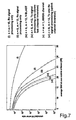
- Figure 7 shows various bit error rate curves as a function of the average signal-to-noise ratio at a receiving antenna as simulation results. Shown is the bit error rate of a system simulation with random errors in the channel estimate corresponding to a sequence length of 128 symbols (BPSK modulation for the pilot sequences, 16-QAM modulation for the data signals) as a function of the signal-to-noise ratio at a receiving antenna for the three transmission schemes A, B and C according to Figure 1. For orientation, V-BLAST and a single-channel transmission in the white noise channel (AWGN) were shown.
- BPSK modulation for the pilot sequences
- 16-QAM modulation 16-QAM modulation for the data signals
- the 12-dimensional noise vector n is projected into an 8-dimensional hyperplane. This initially reduces the noise power by a factor of 8/12, which corresponds to a gain of 1.5 dB.
- the bit error rate for channel inversion in the up and down transmitter direction is essentially the same. Differences arise only in that the signal processing in the downlink transmission direction is based only on a channel estimation at the base station, while in the uplink transmission direction two independent estimates of H at the base station and H T at the mobile station are used. However, this does not include the fact that the transmission power is modified on the basis of the transmitter-side signal processing depending on the current channel matrix H.
- FIG. 8 shows various bit error rate curves as a function of the total transmission power relative to the noise power at a receiver from a simulation (V-BLAST) or from analytical considerations (LCI, AWGN in the single channel). Since the transmit power is statistically distributed at channel inversion, it is fair to plot the curves over the average transmit power relative to the noise at a receiver.
- V-BLAST simulation
- LCI analytical considerations
- FIG. 9 shows the transmit and receive power distributions (power at each Tx antenna, power at each Rx antenna) for the individual schemes A, B, C according to FIG. 1.
- scheme A only receive-side signal processing
- three discrete ones are found at each transmitter Lines that differ in their location only by the number of transmit antennas. All transmit antennas emit the same power on average and the lines result from the possible symbol energies in the selected 16-QAM modulation.
- a broad scattered ⁇ 2 distribution with two degrees of freedom is obtained for the power. The distribution does not depend on the number of transmit antennas because the overall power of the data streams is normalized and the individual transmission channels are statistically independent.
Landscapes
- Engineering & Computer Science (AREA)
- Computer Networks & Wireless Communication (AREA)
- Signal Processing (AREA)
- Physics & Mathematics (AREA)
- Mathematical Physics (AREA)
- Radio Transmission System (AREA)
- Bidirectional Digital Transmission (AREA)
- Mobile Radio Communication Systems (AREA)
- Noise Elimination (AREA)
Claims (9)
- Procédé adaptatif de traitement de signaux pour une transmission radio bidirectionnelle de flux de données numériques dans le sens d'émission ascendant et le sens d'émission descendant au moyen d'un canal MIMO avec n antennes sur un côté de canal et m antennes sur l'autre côté de canal et avec un pré-traitement de signaux côté émission des signaux d'émission x et un post-traitement de signaux côté réception des signaux de réception y, qui sont basés tous deux sur une estimation de la matrice de canal à valeur complexe, dans lequelle pré-traitement de signaux côté émission comprend une multiplication des signaux de données à émettre avec une matrice d'émission et le post-traitement de signaux côté réception une multiplication des signaux de réception avec une matrice de réception, le post-traitement de signaux s'effectuant exclusivement dans le sens d'émission ascendant et les matrices d'émission et de réception étant obtenues à partir d'une décomposition linéaire de la matrice de canal H estimée,dans le sens d'émission ascendant, (n→m) sur le côté émission, on utilise au moins une antenne de plus que du côté émission et dans le sens d'émission descendant, (m→n), du côté émission, on utilise au moins une antenne de plus que sur le côté réception (n < m), etl'estimation pour la matrice de canal H est déterminée dans le cas d'un débit de symboles, choisi en fonction des propriétés du canal, d'au moins 100 ksymboles/s, la matrice du canal étant obtenue dans le sens d'émission descendant par transposition de la matrice de canal à partir de l'estimation dans le sens d'émission ascendant et inversement, avec l'utilisation de la réciprocité du canal MIMO à la même fréquence de transmission dans le sens d'émission ascendant et le sens d'émission descendant et en l'absence de perturbations sur le même canal.
- Procédé adaptatif de traitement de signaux selon la revendication 1,
caractérisé en ce que
dans le sens d'émission ascendant, la matrice d'émission pour la multiplication avec les signaux d'émission x est déterminée sur la base de la décomposition des valeurs singulières de la matrice de canal H avec n < m, qui est donnée par - Procédé adaptatif de traitement de signaux selon la revendication 2,
caractérisé en ce que
l'inverse généralisé est le pseudo-inverse de Moore-Penrose. - Procédé adaptatif de traitement de signaux selon l'une quelconque des revendications 1 à 3,
caractérisé en ce que
pour l'estimation la plus précise possible de la matrice de canal, des signaux pilotes spéciaux, pouvant être générés et reconnus facilement sont envoyés par intermittence ou par superposition en même temps que les signaux d'émission, qui caractérisent clairement chaque antenne. - Procédé adaptatif de traitement de signaux selon la revendication 4,
caractérisé en ce que
les signaux pilotes sont générés à partir de séquences orthogonales, en particulier selon Gold ou Hadamard, avec une longueur de plus de 100 symboles. - Procédé adaptatif de traitement de signaux selon l'une quelconque des revendications 1 à 5,
caractérisé en ce que
la transmission radio s'effectue dans le procédé de duplex temporel. - Procédé adaptatif de traitement de signaux selon l'une quelconque des revendications 1 à 5,
caractérisé en ce que
la transmission s'effectue dans le procédé de duplex de fréquence, les signaux pilotes étant diffusés et détectés toujours sur la même fréquence porteuse, sur laquelle les signaux d'émission sont également émis. - Procédé adaptatif de traitement de signaux selon l'une quelconque des revendications 1 à 7,
caractérisé en ce que
les puissances des perturbations qui apparaissent sur le même canal sont mesurées dans chaque chemin de signal de données apparaissant dans le canal MIMO après la reconstitution des signaux d'émission sur le côté réception et sont retransmis via un canal retour régulièrement au côté d'émission. - Procédé adaptatif de traitement de signaux selon la revendication 8,
caractérisé en ce que
la puissance dans chaque chemin de signal de données apparaissant dans le canal MIMO est adaptée avant le pré-traitement de signaux côté émission à la perturbation sur le même canal, mesurée sur le côté réception à chaque fois après le post-traitement de signaux de telle sorte que le rapport de puissance signal-parasite-plus-bruit est identique dans tous les chemins du signal de données.
Applications Claiming Priority (3)
| Application Number | Priority Date | Filing Date | Title |
|---|---|---|---|
| DE10132492A DE10132492A1 (de) | 2001-07-03 | 2001-07-03 | Adaptives Signalverarbeitungsverfahren zur bidirektionalen Funkübertragung in einem MIMO-Kanal und MIMO-System zur Verfahrensdurchführung |
| DE10132492 | 2001-07-03 | ||
| PCT/DE2002/002494 WO2003005606A1 (fr) | 2001-07-03 | 2002-07-03 | Procede de traitement de signaux adaptatif dans un systeme de simulation |
Publications (2)
| Publication Number | Publication Date |
|---|---|
| EP1402657A1 EP1402657A1 (fr) | 2004-03-31 |
| EP1402657B1 true EP1402657B1 (fr) | 2005-06-01 |
Family
ID=7690636
Family Applications (1)
| Application Number | Title | Priority Date | Filing Date |
|---|---|---|---|
| EP02758084A Expired - Lifetime EP1402657B1 (fr) | 2001-07-03 | 2002-07-03 | Procede de traitement de signaux adaptatif dans un systeme a entrees multiples et sorties multiples |
Country Status (7)
| Country | Link |
|---|---|
| US (1) | US7366520B2 (fr) |
| EP (1) | EP1402657B1 (fr) |
| JP (1) | JP4194038B2 (fr) |
| AT (1) | ATE297077T1 (fr) |
| DE (2) | DE10132492A1 (fr) |
| ES (1) | ES2240785T3 (fr) |
| WO (1) | WO2003005606A1 (fr) |
Families Citing this family (79)
| Publication number | Priority date | Publication date | Assignee | Title |
|---|---|---|---|---|
| US7952511B1 (en) | 1999-04-07 | 2011-05-31 | Geer James L | Method and apparatus for the detection of objects using electromagnetic wave attenuation patterns |
| US7295509B2 (en) | 2000-09-13 | 2007-11-13 | Qualcomm, Incorporated | Signaling method in an OFDM multiple access system |
| US9130810B2 (en) | 2000-09-13 | 2015-09-08 | Qualcomm Incorporated | OFDM communications methods and apparatus |
| US7145959B2 (en) | 2001-04-25 | 2006-12-05 | Magnolia Broadband Inc. | Smart antenna based spectrum multiplexing using existing pilot signals for orthogonal frequency division multiplexing (OFDM) modulations |
| US8249187B2 (en) | 2002-05-09 | 2012-08-21 | Google Inc. | System, method and apparatus for mobile transmit diversity using symmetric phase difference |
| CN1545770B (zh) | 2001-05-31 | 2013-03-06 | 马格诺利亚宽带股份有限公司 | 通信方法和设备以及用于改进通信设备的系统性能的方法 |
| JP2003032164A (ja) * | 2001-07-18 | 2003-01-31 | Hitachi Kokusai Electric Inc | 通信機 |
| US7327798B2 (en) | 2001-10-19 | 2008-02-05 | Lg Electronics Inc. | Method and apparatus for transmitting/receiving signals in multiple-input multiple-output communication system provided with plurality of antenna elements |
| KR100463526B1 (ko) * | 2002-01-04 | 2004-12-29 | 엘지전자 주식회사 | 다중 입력 다중 출력 시스템에서의 전력 할당 방법 |
| DK1540830T3 (da) * | 2002-07-30 | 2009-05-04 | Ipr Licensing Inc | System og metode til flerheds input (MIMO) radio kommunikation |
| US8179864B2 (en) | 2002-08-06 | 2012-05-15 | Rockstar Bidco Lp | Method of controlling a communications link |
| US7184500B2 (en) | 2002-12-30 | 2007-02-27 | Magnolia Broadband Inc. | Method and system for adaptively combining signals |
| US7099678B2 (en) * | 2003-04-10 | 2006-08-29 | Ipr Licensing, Inc. | System and method for transmit weight computation for vector beamforming radio communication |
| US7418067B1 (en) | 2003-04-14 | 2008-08-26 | Magnolia Broadband Inc. | Processing diversity signals at a mobile device using phase adjustments |
| JPWO2005008931A1 (ja) * | 2003-07-16 | 2006-09-28 | 日本電気株式会社 | 送信装置、受信装置、無線通信システム |
| US8712428B2 (en) * | 2003-07-19 | 2014-04-29 | Polaris Wireless, Inc. | Location estimation of wireless terminals through pattern matching of deduced signal strengths |
| WO2005011178A2 (fr) * | 2003-07-21 | 2005-02-03 | Zyray Wireless, Inc. | Procede de generation de poids destine a des systemes de communication a antennes multiples utilisant la ponderation et la combinaison de signaux bases rf et a bande de base basee sur un taux d'erreur binaire minimum |
| US8908496B2 (en) * | 2003-09-09 | 2014-12-09 | Qualcomm Incorporated | Incremental redundancy transmission in a MIMO communication system |
| US7120395B2 (en) * | 2003-10-20 | 2006-10-10 | Nortel Networks Limited | MIMO communications |
| US7430430B2 (en) | 2003-12-16 | 2008-09-30 | Magnolia Broadband Inc. | Adjusting a signal at a diversity system |
| US7272359B2 (en) * | 2004-01-26 | 2007-09-18 | Magnolia Broadband Inc. | Communicating signals according to a quality indicator using multiple antenna elements |
| GB2411328B (en) * | 2004-02-23 | 2007-05-16 | Toshiba Res Europ Ltd | Adaptive MIMO systems |
| JP4367659B2 (ja) * | 2004-03-26 | 2009-11-18 | 日本電気株式会社 | 無線通信機 |
| US7327983B2 (en) * | 2004-06-25 | 2008-02-05 | Mitsubishi Electric Research Laboratories, Inc. | RF-based antenna selection in MIMO systems |
| US9148256B2 (en) | 2004-07-21 | 2015-09-29 | Qualcomm Incorporated | Performance based rank prediction for MIMO design |
| US9137822B2 (en) | 2004-07-21 | 2015-09-15 | Qualcomm Incorporated | Efficient signaling over access channel |
| JP4744965B2 (ja) * | 2004-08-09 | 2011-08-10 | パナソニック株式会社 | 無線通信装置 |
| CN100375561C (zh) * | 2004-09-13 | 2008-03-12 | 大唐移动通信设备有限公司 | 多载波时分双工移动通信系统分配无线资源的方法 |
| US7239659B2 (en) * | 2004-11-04 | 2007-07-03 | Motorola, Inc. | Method and apparatus for channel feedback |
| US20070041322A1 (en) * | 2005-01-12 | 2007-02-22 | Won-Joon Choi | Rate adaptation using semi-open loop technique |
| JP4599192B2 (ja) * | 2005-03-02 | 2010-12-15 | 株式会社日立製作所 | 無線データ通信システム、および、無線データ通信方法 |
| US9246560B2 (en) | 2005-03-10 | 2016-01-26 | Qualcomm Incorporated | Systems and methods for beamforming and rate control in a multi-input multi-output communication systems |
| US9154211B2 (en) | 2005-03-11 | 2015-10-06 | Qualcomm Incorporated | Systems and methods for beamforming feedback in multi antenna communication systems |
| US8446892B2 (en) | 2005-03-16 | 2013-05-21 | Qualcomm Incorporated | Channel structures for a quasi-orthogonal multiple-access communication system |
| US9143305B2 (en) | 2005-03-17 | 2015-09-22 | Qualcomm Incorporated | Pilot signal transmission for an orthogonal frequency division wireless communication system |
| US9520972B2 (en) * | 2005-03-17 | 2016-12-13 | Qualcomm Incorporated | Pilot signal transmission for an orthogonal frequency division wireless communication system |
| US9461859B2 (en) | 2005-03-17 | 2016-10-04 | Qualcomm Incorporated | Pilot signal transmission for an orthogonal frequency division wireless communication system |
| US9184870B2 (en) | 2005-04-01 | 2015-11-10 | Qualcomm Incorporated | Systems and methods for control channel signaling |
| US20060229029A1 (en) * | 2005-04-07 | 2006-10-12 | Intel Corporation | Ultra high frequency / very high frequency (UHF/VHF) band enhancement |
| US9036538B2 (en) | 2005-04-19 | 2015-05-19 | Qualcomm Incorporated | Frequency hopping design for single carrier FDMA systems |
| US9408220B2 (en) | 2005-04-19 | 2016-08-02 | Qualcomm Incorporated | Channel quality reporting for adaptive sectorization |
| US8879511B2 (en) | 2005-10-27 | 2014-11-04 | Qualcomm Incorporated | Assignment acknowledgement for a wireless communication system |
| US8611284B2 (en) | 2005-05-31 | 2013-12-17 | Qualcomm Incorporated | Use of supplemental assignments to decrement resources |
| US8565194B2 (en) | 2005-10-27 | 2013-10-22 | Qualcomm Incorporated | Puncturing signaling channel for a wireless communication system |
| US8462859B2 (en) | 2005-06-01 | 2013-06-11 | Qualcomm Incorporated | Sphere decoding apparatus |
| US8599945B2 (en) | 2005-06-16 | 2013-12-03 | Qualcomm Incorporated | Robust rank prediction for a MIMO system |
| US9179319B2 (en) | 2005-06-16 | 2015-11-03 | Qualcomm Incorporated | Adaptive sectorization in cellular systems |
| US8885628B2 (en) | 2005-08-08 | 2014-11-11 | Qualcomm Incorporated | Code division multiplexing in a single-carrier frequency division multiple access system |
| US7907911B2 (en) * | 2005-08-16 | 2011-03-15 | Alcatel-Lucent Usa Inc. | Scheduling multi-user transmission in the downlink of a multi-antenna wireless communication system |
| US9209956B2 (en) | 2005-08-22 | 2015-12-08 | Qualcomm Incorporated | Segment sensitive scheduling |
| US20070041457A1 (en) | 2005-08-22 | 2007-02-22 | Tamer Kadous | Method and apparatus for providing antenna diversity in a wireless communication system |
| US8644292B2 (en) | 2005-08-24 | 2014-02-04 | Qualcomm Incorporated | Varied transmission time intervals for wireless communication system |
| US9136974B2 (en) | 2005-08-30 | 2015-09-15 | Qualcomm Incorporated | Precoding and SDMA support |
| US9225488B2 (en) | 2005-10-27 | 2015-12-29 | Qualcomm Incorporated | Shared signaling channel |
| US9225416B2 (en) | 2005-10-27 | 2015-12-29 | Qualcomm Incorporated | Varied signaling channels for a reverse link in a wireless communication system |
| US9172453B2 (en) | 2005-10-27 | 2015-10-27 | Qualcomm Incorporated | Method and apparatus for pre-coding frequency division duplexing system |
| US9088384B2 (en) | 2005-10-27 | 2015-07-21 | Qualcomm Incorporated | Pilot symbol transmission in wireless communication systems |
| US8582509B2 (en) | 2005-10-27 | 2013-11-12 | Qualcomm Incorporated | Scalable frequency band operation in wireless communication systems |
| US8045512B2 (en) | 2005-10-27 | 2011-10-25 | Qualcomm Incorporated | Scalable frequency band operation in wireless communication systems |
| US9210651B2 (en) | 2005-10-27 | 2015-12-08 | Qualcomm Incorporated | Method and apparatus for bootstraping information in a communication system |
| US8477684B2 (en) | 2005-10-27 | 2013-07-02 | Qualcomm Incorporated | Acknowledgement of control messages in a wireless communication system |
| US9144060B2 (en) | 2005-10-27 | 2015-09-22 | Qualcomm Incorporated | Resource allocation for shared signaling channels |
| US8693405B2 (en) | 2005-10-27 | 2014-04-08 | Qualcomm Incorporated | SDMA resource management |
| US8582548B2 (en) | 2005-11-18 | 2013-11-12 | Qualcomm Incorporated | Frequency division multiple access schemes for wireless communication |
| EP1799001A1 (fr) * | 2005-12-15 | 2007-06-20 | Siemens Aktiengesellschaft | Procédé pour l'attribution de ressources de bandes de fréquence d'un système de communication sans fil et appareil de réseau et station d'abonné |
| EP1858180B1 (fr) * | 2006-05-19 | 2009-05-20 | Rohde & Schwarz GmbH & Co. KG | Système et procédé pour l'essai et la simulation de canaux dans un système de radiocommunications mobiles |
| BRPI0714275A2 (pt) | 2006-08-07 | 2013-04-16 | Interdigital Tech Corp | mÉtodo, aparelho e sistema de implementaÇço de méltiplas entradas e méltiplas saÍdas virtual de méltiplos usuÁrios. |
| EP2100454B1 (fr) | 2006-11-20 | 2019-10-30 | Axis AB | Systèmes de réseau de caméras sans fil |
| US7801238B2 (en) * | 2007-03-30 | 2010-09-21 | Alcatel-Lucent Usa Inc. | MIMO communication system with user scheduling based on reduced channel state information |
| US8144759B2 (en) * | 2007-05-04 | 2012-03-27 | University Of Central Florida Research Foundation, Inc. | Adaptive methods employing optimal convergence factors for processing complex signals and systems |
| EP2238758A4 (fr) | 2008-01-24 | 2013-12-18 | Micropower Technologies Inc | Systèmes de distribution de vidéo utilisant des caméras sans fil |
| CN102055692B (zh) * | 2009-10-28 | 2013-11-06 | 中兴通讯股份有限公司 | 一种多天线系统中的信道估计方法及装置 |
| CN102843759B (zh) * | 2011-06-23 | 2016-03-02 | 华为技术有限公司 | 一种上行多入多出信道的功率控制方法和用户设备 |
| JP6151074B2 (ja) * | 2013-04-15 | 2017-06-21 | 京セラ株式会社 | 通信システムおよび通信制御方法 |
| US9397761B2 (en) | 2013-05-17 | 2016-07-19 | Crfs Limited | RF signal generating device |
| US9461698B2 (en) | 2013-11-27 | 2016-10-04 | Harris Corporation | Communications device with simultaneous transmit and receive and related methods |
| KR101599190B1 (ko) * | 2015-03-19 | 2016-03-04 | 전북대학교산학협력단 | 블록 순환 재킷 행렬을 이용한 mimo 통신 방법 및 시스템 |
| CN111371517B (zh) * | 2018-12-26 | 2021-06-25 | 大唐移动通信设备有限公司 | 一种远端干扰互易性评估方法及装置 |
| CN115765880A (zh) * | 2021-09-03 | 2023-03-07 | 华为技术有限公司 | 通信方法、装置及系统 |
Family Cites Families (6)
| Publication number | Priority date | Publication date | Assignee | Title |
|---|---|---|---|---|
| WO1998009385A2 (fr) * | 1996-08-29 | 1998-03-05 | Cisco Technology, Inc. | Traitement spatio-temporel pour telecommunications |
| US6141393A (en) * | 1999-03-03 | 2000-10-31 | Motorola, Inc. | Method and device for channel estimation, equalization, and interference suppression |
| US7062294B1 (en) * | 2000-09-29 | 2006-06-13 | Arraycomm, Llc. | Downlink transmission in a wireless data communication system having a base station with a smart antenna system |
| US6771706B2 (en) * | 2001-03-23 | 2004-08-03 | Qualcomm Incorporated | Method and apparatus for utilizing channel state information in a wireless communication system |
| US20030031264A1 (en) * | 2001-08-07 | 2003-02-13 | Barry John R. | System and method for adaptive channel diagonalization for array-to-array wireless communications |
| US7719993B2 (en) * | 2004-12-30 | 2010-05-18 | Intel Corporation | Downlink transmit beamforming |
-
2001
- 2001-07-03 DE DE10132492A patent/DE10132492A1/de not_active Withdrawn
-
2002
- 2002-07-03 DE DE50203286T patent/DE50203286D1/de not_active Expired - Lifetime
- 2002-07-03 US US10/483,012 patent/US7366520B2/en not_active Expired - Lifetime
- 2002-07-03 WO PCT/DE2002/002494 patent/WO2003005606A1/fr not_active Ceased
- 2002-07-03 JP JP2003511445A patent/JP4194038B2/ja not_active Expired - Fee Related
- 2002-07-03 EP EP02758084A patent/EP1402657B1/fr not_active Expired - Lifetime
- 2002-07-03 ES ES02758084T patent/ES2240785T3/es not_active Expired - Lifetime
- 2002-07-03 AT AT02758084T patent/ATE297077T1/de not_active IP Right Cessation
Also Published As
| Publication number | Publication date |
|---|---|
| JP2004537205A (ja) | 2004-12-09 |
| WO2003005606A1 (fr) | 2003-01-16 |
| ES2240785T3 (es) | 2005-10-16 |
| JP4194038B2 (ja) | 2008-12-10 |
| DE10132492A1 (de) | 2003-01-23 |
| US7366520B2 (en) | 2008-04-29 |
| US20040171385A1 (en) | 2004-09-02 |
| ATE297077T1 (de) | 2005-06-15 |
| EP1402657A1 (fr) | 2004-03-31 |
| DE50203286D1 (de) | 2005-07-07 |
Similar Documents
| Publication | Publication Date | Title |
|---|---|---|
| EP1402657B1 (fr) | Procede de traitement de signaux adaptatif dans un systeme a entrees multiples et sorties multiples | |
| DE60017836T2 (de) | Drahtloses System mit Mehrfachsendeantennenanordnung mit Kombination van Sende-Diversity mit offenem Regelkreis und mit geschlossenem Regelkreis | |
| EP1297639B1 (fr) | Procede de formation de faisceau | |
| EP1563630B1 (fr) | Procede de traitement bidirectionnel de signaux pour systeme mimo (a entrees multiples - a sorties multiples) avec adaptation de la vitesse de transmission adaptative au rang | |
| EP1374419B1 (fr) | Procede de radiotransmission dans la zone interieure pour assurer une radiotransmission parallele de flux partiels de donnees numeriques et systeme de radiotransmission mobile | |
| DE602004005896T2 (de) | Kalibrierverfahren zur erzielung von reziprozität bidirektionaler kommunikationskanäle | |
| DE69929788T2 (de) | Verfahren und vorrichtung zur diversitätsübertragung | |
| DE60029012T2 (de) | Verfahren und vorrichtung für sende-diversity | |
| DE60217706T2 (de) | Stfbc-kodierungs-/-dekodierungsvorrichtung und -verfahren in einem ofdm-mobilkommunikationssystem | |
| DE60316385T2 (de) | Vorrichtung und Verfahren zur Datenübertragung mit Sendeantennendiversität in einem Kommunikationssystem mit Paketdiensten | |
| DE10026077B4 (de) | Strahlformungsverfahren | |
| DE60028838T2 (de) | Verfahren, vorrichtungen und telekommunikationsnetzwerk zum regeln der antennengewichte eines transceivers | |
| DE60131576T2 (de) | Rückgekoppeltes regelungsverfahren für mehrere sendeantennenkeulen und entsprechender transceiver | |
| DE602004012136T2 (de) | Verfahren und vorrichtung für ein mehrstrahl-antennensystem | |
| DE60214340T2 (de) | Drahtlose Kommunikation mittels Vielfachsende- und Vielfachempfangs-Antennenanordnung | |
| DE60219605T2 (de) | Verfahren und vorrichtung zur verwendung von kanalzustandsinformationen (csi) in einem drahtlosen kommunikationssystem | |
| DE60308193T2 (de) | Gruppenempfänger mit subarraysauswahl, verfahren unter verwendung derselben, und empfänger derselben enthaltend | |
| DE69931521T2 (de) | Rake-Empfänger | |
| DE60036546T2 (de) | Verfahren und vorrichtung zur sendeleistungsregelung in einem übertragungssystem unter verwendung von orthogonaler sender-diversität | |
| DE60010408T2 (de) | Sende-diversity verfahren und system | |
| DE69725995T2 (de) | Raumzeitliche signalverarbeitung für übertragungssysteme | |
| DE60314924T2 (de) | Messverfahren zur räumlichen ablaufplanung | |
| DE69900645T2 (de) | Sende-Diversity Verfahren und System mit Phasenregelung für Funkübertragungssysteme | |
| DE60131391T2 (de) | Datenübertragungsverfahren | |
| EP1125376B1 (fr) | Procede et station radio pour la transmission de signaux predistordus par l'intermediaire de plusieurs canaux radio |
Legal Events
| Date | Code | Title | Description |
|---|---|---|---|
| PUAI | Public reference made under article 153(3) epc to a published international application that has entered the european phase |
Free format text: ORIGINAL CODE: 0009012 |
|
| 17P | Request for examination filed |
Effective date: 20031103 |
|
| AK | Designated contracting states |
Kind code of ref document: A1 Designated state(s): AT BE BG CH CY CZ DE DK EE ES FI FR GB GR IE IT LI LU MC NL PT SE SK TR |
|
| AX | Request for extension of the european patent |
Extension state: AL LT LV MK RO SI |
|
| RIN1 | Information on inventor provided before grant (corrected) |
Inventor name: WUNDER, GERHARD Inventor name: JORSWIECK, EDUARD Inventor name: HAUSTEIN, THOMAS Inventor name: KRUEGER, UDO Inventor name: V. HELMOT, CLEMENS Inventor name: JUNGNICKEL, VOLKER Inventor name: POHL, VOLKER |
|
| GRAP | Despatch of communication of intention to grant a patent |
Free format text: ORIGINAL CODE: EPIDOSNIGR1 |
|
| RAP1 | Party data changed (applicant data changed or rights of an application transferred) |
Owner name: FRAUNHOFER-GESELLSCHAFT ZUR FOERDERUNG DERANGEWAND |
|
| RIN1 | Information on inventor provided before grant (corrected) |
Inventor name: V. HELMOT, CLEMENS Inventor name: JORSWIECK, EDUARD Inventor name: WUNDER, GERHARD Inventor name: JUNGNICKEL, VOLKER Inventor name: HAUSTEIN, THOMAS Inventor name: POHL, VOLKER Inventor name: KRUEGER, UDO |
|
| RAP1 | Party data changed (applicant data changed or rights of an application transferred) |
Owner name: FRAUNHOFER-GESELLSCHAFT ZURFOERDERUNG DER ANGEWAND |
|
| GRAS | Grant fee paid |
Free format text: ORIGINAL CODE: EPIDOSNIGR3 |
|
| RAP1 | Party data changed (applicant data changed or rights of an application transferred) |
Owner name: SIEMENS AKTIENGESELLSCHAFT |
|
| GRAA | (expected) grant |
Free format text: ORIGINAL CODE: 0009210 |
|
| AK | Designated contracting states |
Kind code of ref document: B1 Designated state(s): AT BE BG CH CY CZ DE DK EE ES FI FR GB GR IE IT LI LU MC NL PT SE SK TR |
|
| PG25 | Lapsed in a contracting state [announced via postgrant information from national office to epo] |
Ref country code: IT Free format text: LAPSE BECAUSE OF FAILURE TO SUBMIT A TRANSLATION OF THE DESCRIPTION OR TO PAY THE FEE WITHIN THE PRESCRIBED TIME-LIMIT;WARNING: LAPSES OF ITALIAN PATENTS WITH EFFECTIVE DATE BEFORE 2007 MAY HAVE OCCURRED AT ANY TIME BEFORE 2007. THE CORRECT EFFECTIVE DATE MAY BE DIFFERENT FROM THE ONE RECORDED. Effective date: 20050601 Ref country code: EE Free format text: LAPSE BECAUSE OF FAILURE TO SUBMIT A TRANSLATION OF THE DESCRIPTION OR TO PAY THE FEE WITHIN THE PRESCRIBED TIME-LIMIT Effective date: 20050601 Ref country code: TR Free format text: LAPSE BECAUSE OF FAILURE TO SUBMIT A TRANSLATION OF THE DESCRIPTION OR TO PAY THE FEE WITHIN THE PRESCRIBED TIME-LIMIT Effective date: 20050601 Ref country code: IE Free format text: LAPSE BECAUSE OF FAILURE TO SUBMIT A TRANSLATION OF THE DESCRIPTION OR TO PAY THE FEE WITHIN THE PRESCRIBED TIME-LIMIT Effective date: 20050601 Ref country code: FI Free format text: LAPSE BECAUSE OF FAILURE TO SUBMIT A TRANSLATION OF THE DESCRIPTION OR TO PAY THE FEE WITHIN THE PRESCRIBED TIME-LIMIT Effective date: 20050601 Ref country code: NL Free format text: LAPSE BECAUSE OF FAILURE TO SUBMIT A TRANSLATION OF THE DESCRIPTION OR TO PAY THE FEE WITHIN THE PRESCRIBED TIME-LIMIT Effective date: 20050601 |
|
| REG | Reference to a national code |
Ref country code: GB Ref legal event code: FG4D Free format text: NOT ENGLISH |
|
| REG | Reference to a national code |
Ref country code: CH Ref legal event code: EP |
|
| GBT | Gb: translation of ep patent filed (gb section 77(6)(a)/1977) |
Effective date: 20050601 |
|
| PG25 | Lapsed in a contracting state [announced via postgrant information from national office to epo] |
Ref country code: LU Free format text: LAPSE BECAUSE OF NON-PAYMENT OF DUE FEES Effective date: 20050703 Ref country code: CY Free format text: LAPSE BECAUSE OF FAILURE TO SUBMIT A TRANSLATION OF THE DESCRIPTION OR TO PAY THE FEE WITHIN THE PRESCRIBED TIME-LIMIT Effective date: 20050703 Ref country code: AT Free format text: LAPSE BECAUSE OF NON-PAYMENT OF DUE FEES Effective date: 20050703 |
|
| REF | Corresponds to: |
Ref document number: 50203286 Country of ref document: DE Date of ref document: 20050707 Kind code of ref document: P |
|
| REG | Reference to a national code |
Ref country code: IE Ref legal event code: FG4D Free format text: LANGUAGE OF EP DOCUMENT: GERMAN |
|
| PG25 | Lapsed in a contracting state [announced via postgrant information from national office to epo] |
Ref country code: MC Free format text: LAPSE BECAUSE OF NON-PAYMENT OF DUE FEES Effective date: 20050731 Ref country code: BE Free format text: LAPSE BECAUSE OF NON-PAYMENT OF DUE FEES Effective date: 20050731 |
|
| PG25 | Lapsed in a contracting state [announced via postgrant information from national office to epo] |
Ref country code: SE Free format text: LAPSE BECAUSE OF FAILURE TO SUBMIT A TRANSLATION OF THE DESCRIPTION OR TO PAY THE FEE WITHIN THE PRESCRIBED TIME-LIMIT Effective date: 20050901 Ref country code: BG Free format text: LAPSE BECAUSE OF FAILURE TO SUBMIT A TRANSLATION OF THE DESCRIPTION OR TO PAY THE FEE WITHIN THE PRESCRIBED TIME-LIMIT Effective date: 20050901 Ref country code: DK Free format text: LAPSE BECAUSE OF FAILURE TO SUBMIT A TRANSLATION OF THE DESCRIPTION OR TO PAY THE FEE WITHIN THE PRESCRIBED TIME-LIMIT Effective date: 20050901 Ref country code: GR Free format text: LAPSE BECAUSE OF FAILURE TO SUBMIT A TRANSLATION OF THE DESCRIPTION OR TO PAY THE FEE WITHIN THE PRESCRIBED TIME-LIMIT Effective date: 20050901 |
|
| REG | Reference to a national code |
Ref country code: ES Ref legal event code: FG2A Ref document number: 2240785 Country of ref document: ES Kind code of ref document: T3 |
|
| PG25 | Lapsed in a contracting state [announced via postgrant information from national office to epo] |
Ref country code: PT Free format text: LAPSE BECAUSE OF FAILURE TO SUBMIT A TRANSLATION OF THE DESCRIPTION OR TO PAY THE FEE WITHIN THE PRESCRIBED TIME-LIMIT Effective date: 20051103 |
|
| NLV1 | Nl: lapsed or annulled due to failure to fulfill the requirements of art. 29p and 29m of the patents act | ||
| REG | Reference to a national code |
Ref country code: IE Ref legal event code: FD4D |
|
| PLBE | No opposition filed within time limit |
Free format text: ORIGINAL CODE: 0009261 |
|
| STAA | Information on the status of an ep patent application or granted ep patent |
Free format text: STATUS: NO OPPOSITION FILED WITHIN TIME LIMIT |
|
| ET | Fr: translation filed | ||
| 26N | No opposition filed |
Effective date: 20060302 |
|
| PG25 | Lapsed in a contracting state [announced via postgrant information from national office to epo] |
Ref country code: CH Free format text: LAPSE BECAUSE OF NON-PAYMENT OF DUE FEES Effective date: 20060731 Ref country code: LI Free format text: LAPSE BECAUSE OF NON-PAYMENT OF DUE FEES Effective date: 20060731 |
|
| REG | Reference to a national code |
Ref country code: CH Ref legal event code: PL |
|
| BERE | Be: lapsed |
Owner name: SIEMENS A.G. Effective date: 20050731 |
|
| PGFP | Annual fee paid to national office [announced via postgrant information from national office to epo] |
Ref country code: CZ Payment date: 20140627 Year of fee payment: 13 |
|
| PGFP | Annual fee paid to national office [announced via postgrant information from national office to epo] |
Ref country code: SK Payment date: 20140701 Year of fee payment: 13 |
|
| REG | Reference to a national code |
Ref country code: SK Ref legal event code: MM4A Ref document number: E 188 Country of ref document: SK Effective date: 20150703 |
|
| PG25 | Lapsed in a contracting state [announced via postgrant information from national office to epo] |
Ref country code: CZ Free format text: LAPSE BECAUSE OF NON-PAYMENT OF DUE FEES Effective date: 20150703 Ref country code: SK Free format text: LAPSE BECAUSE OF NON-PAYMENT OF DUE FEES Effective date: 20150703 |
|
| REG | Reference to a national code |
Ref country code: FR Ref legal event code: PLFP Year of fee payment: 15 |
|
| REG | Reference to a national code |
Ref country code: FR Ref legal event code: PLFP Year of fee payment: 16 |
|
| REG | Reference to a national code |
Ref country code: FR Ref legal event code: PLFP Year of fee payment: 17 |
|
| PGFP | Annual fee paid to national office [announced via postgrant information from national office to epo] |
Ref country code: ES Payment date: 20181026 Year of fee payment: 17 |
|
| PGFP | Annual fee paid to national office [announced via postgrant information from national office to epo] |
Ref country code: DE Payment date: 20190919 Year of fee payment: 18 Ref country code: FR Payment date: 20190716 Year of fee payment: 18 |
|
| PGFP | Annual fee paid to national office [announced via postgrant information from national office to epo] |
Ref country code: GB Payment date: 20190702 Year of fee payment: 18 |
|
| REG | Reference to a national code |
Ref country code: ES Ref legal event code: FD2A Effective date: 20201126 |
|
| PG25 | Lapsed in a contracting state [announced via postgrant information from national office to epo] |
Ref country code: ES Free format text: LAPSE BECAUSE OF NON-PAYMENT OF DUE FEES Effective date: 20190704 |
|
| REG | Reference to a national code |
Ref country code: DE Ref legal event code: R119 Ref document number: 50203286 Country of ref document: DE |
|
| GBPC | Gb: european patent ceased through non-payment of renewal fee |
Effective date: 20200703 |
|
| PG25 | Lapsed in a contracting state [announced via postgrant information from national office to epo] |
Ref country code: GB Free format text: LAPSE BECAUSE OF NON-PAYMENT OF DUE FEES Effective date: 20200703 Ref country code: FR Free format text: LAPSE BECAUSE OF NON-PAYMENT OF DUE FEES Effective date: 20200731 |
|
| PG25 | Lapsed in a contracting state [announced via postgrant information from national office to epo] |
Ref country code: DE Free format text: LAPSE BECAUSE OF NON-PAYMENT OF DUE FEES Effective date: 20210202 |