EP1284067B1 - Verfahren und vorrichtung zur kollisionsvermeidenden signalübertragung - Google Patents
Verfahren und vorrichtung zur kollisionsvermeidenden signalübertragung Download PDFInfo
- Publication number
- EP1284067B1 EP1284067B1 EP00974192A EP00974192A EP1284067B1 EP 1284067 B1 EP1284067 B1 EP 1284067B1 EP 00974192 A EP00974192 A EP 00974192A EP 00974192 A EP00974192 A EP 00974192A EP 1284067 B1 EP1284067 B1 EP 1284067B1
- Authority
- EP
- European Patent Office
- Prior art keywords
- signal
- signals
- signal part
- transmission
- transmission speed
- Prior art date
- Legal status (The legal status is an assumption and is not a legal conclusion. Google has not performed a legal analysis and makes no representation as to the accuracy of the status listed.)
- Expired - Lifetime
Links
- 238000000034 method Methods 0.000 title claims abstract description 30
- 230000008054 signal transmission Effects 0.000 title claims abstract description 18
- 230000005540 biological transmission Effects 0.000 claims abstract description 50
- 239000004020 conductor Substances 0.000 description 2
- 230000004075 alteration Effects 0.000 description 1
- 230000006735 deficit Effects 0.000 description 1
- 238000005259 measurement Methods 0.000 description 1
- 230000003287 optical effect Effects 0.000 description 1
Images
Classifications
-
- H—ELECTRICITY
- H04—ELECTRIC COMMUNICATION TECHNIQUE
- H04L—TRANSMISSION OF DIGITAL INFORMATION, e.g. TELEGRAPHIC COMMUNICATION
- H04L12/00—Data switching networks
- H04L12/28—Data switching networks characterised by path configuration, e.g. LAN [Local Area Networks] or WAN [Wide Area Networks]
- H04L12/40—Bus networks
- H04L12/407—Bus networks with decentralised control
-
- H—ELECTRICITY
- H04—ELECTRIC COMMUNICATION TECHNIQUE
- H04L—TRANSMISSION OF DIGITAL INFORMATION, e.g. TELEGRAPHIC COMMUNICATION
- H04L12/00—Data switching networks
- H04L12/28—Data switching networks characterised by path configuration, e.g. LAN [Local Area Networks] or WAN [Wide Area Networks]
- H04L12/40—Bus networks
- H04L12/4013—Management of data rate on the bus
Definitions
- the present invention relates to a method and a device for signal transmission.
- a large disadvantage of signal transmission as it is performed nowadays consists in that, by increasing the transmission speed, also the risk of so-called collisions is increased, which collisions occur as two or more signals are transmitted by two or more senders at approximately the same point in time over one and the same transmission network. Then, the two signals will interfere with each other, as a result of which they will be deformed in such a manner that it will no longer be possible to filter the original message out of it and both signals will have to be sent again, with the consequence that precious time will be lost. In other words, a saturation of the transmission network is created, as a result of which in some cases up to 80 or 90 % of the capacity is taken up by signals which have to be sent again after a collision has occurred.
- the present invention has as an aim to bring about a considerable increase of the usable capacity of a transmission network and to prevent the disturbance of signals as a consequence of the simultaneous transmission of several signals.
- the invention in the first place relates to a method for signal transmission, whereby use is made of signals consisting of at least a first signal part consisting of a pulse train and a second signal part, whereby the method consists in trans-mitting the first signal part with a first transmission speed, with the aim of preventing disturbances occurring as a result of the simultaneous presence of several signals; and subsequently transmitting the pertaining second signal part with a second transmission speed after having obtained, by the transmission of the first signal part, the certainty that the second signal part can be transmitted free of at least a number of disturbances, whereby the second transmission speed is higher than the first transmission speed.
- the aforementioned control can be performed with a high certainty.
- sending the second signal part with a higher transmission speed it is possible to subsequently send a large quantity of information in a safe manner, without a disturbance occuring.
- the first signal part will be used for giving priority to one signal when transmitting two or more different signals.
- the second signal part is transmitted only after priority has been obtained by means of the pertaining first signal part.
- the transmission speed of the second signal part is at least five times higher and even better is ten times higher than the transmission speed of the first signal part, as a result of which a lot of information can be transmitted in a short period of time.
- the transmission of the first signal part and/or of the second signal part preferably use is made of pulse width modulation, as, on the basis thereof, it is possible to easily perform a selection between the first signal parts of several signals, if these latter signals should be present on the transmission network at the same time.
- the first signal part and/or the second signal part can be double-modulated, in other words, can be processed such that a modulation is performed as well at the lower as at the higher level of the signals, more particularly the lower and higher levels of the pulses of which these signals are formed.
- the transmission speed of the first signal part is less than 20,000 bits/second.
- the transmission speed of the second signal part is higher than 60,000 bits/second.
- a disturbance may by created by signals which are put on the transmission network at the same time or approximately the same time, but that also, when putting a signal on the transmission network, it is immediately verified at the location where it is placed whether a signal is already present, in particular, it is verified whether during a certain period no other signal is present on the location where the first-mentioned signal is transmitted, and the first-mentioned signal only is passed when during the aforementioned period of time no other signal is detected at the aforementioned location, which period at least corresponds to the transmission time of the longest bit possible. As a result thereof, it is excluded that the control is performed just in between two pulses, whereby nothing would be detected.
- pulses shall be applied whereby the smallest period which can be covered by such pulse is larger than the time necessary for a fraction of a signal to travel the longest possible path over which the signals are transmitted in one time. This allows to compare the first signal parts of different signals bit by bit.
- the length of a pulse-shaped signal would be twice the aforementioned time.
- the length of the aforementioned pulse-shaped signal shall be at least of the order of magnitude of 50 ⁇ s.
- the invention also relates to devices, consisting of a transmission network with units for signal transmission and signal receiving in which the method described heretofore is applied.
- the invention is, amongst others, especially useful in domotics- or immotics-applications.
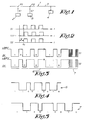
- a transmission network 1 is represented schematically, with units 2-3-4 by means of which signals can be transmitted over a carrier 5, in this case, for example, an electric conductor, and signals can be received, respectively.
- units 2 and 3 emit signals S1 and S2, whereas unit 4, for example, forms a unit which has to be commanded by means of the aforementioned signals.
- the aforementioned waiting time will have at least the duration of the longest bit of a signal in order to offer the certainty that the line is free at the location where the corresponding signal is put on carrier 5.
- Said waiting time does not allow to exclude any possibility of interference of signals, as hereafter explained by means of figure 2.
- Figure 2 shows three curves, respectively of the signal S1 on the location P1 in figure 1, of signal S2 on the location P2 in figure 1, whereby this signal then is denominated SIA, as well as of signal S2 at the location P2.
- the second and third curves of figure 2 show that, notwithstanding the fact that a waiting time W had been taken into account in which no signal had been detected on the location P2, there is a signal, namely, the signal S1, present on carrier 5. At the moment t1, signal S1 actually has not reached location P2, but nevertheless has left location P1. As signal S2 is put on carrier 5 at that moment, both signals S1 and S2 are present on this carrier 5 at the same time, which may lead to the aforementioned disadvantages.
- signals S1 and S2 which, according to the invention, substantially consist of two parts, namely, a first signal part 6 with a first transmission speed and a second signal part 7, with a second, higher transmission speed.
- transmission speed the speed has to be understood with which information is transmitted, in other words, the number of bits per second.
- Figure 3 shows that both signals S1 and S2 are simultaneously present on carrier 5.
- the course of the first signal parts 6 is followed up. From the moment that the signal detected at unit 2 on carrier 5 no longer corresponds to the signal emitted by unit 2, signal S1 is stopped immediately. The same is valid for unit 3 in the case that at said unit 3 a signal should be detected on carrier 5 which no longer corresponds to the signal S2 emitted by unit 3 itself. In such manner, it is obtained that signals S1 and S2 can be present on carrier 5 at the same time exclusively in the case that they are identical. If not, only one signal S1 or S2 will remain, as, such as aforementioned, then a priority will be given to one of the signals S1 or S2.
- the second signal part 7 of the signal which is let through, in this case, signal S1 is transmitted, preferably at a higher transmission speed than the first signal part 6.
- the capacity of the transmission network over which the corresponding signal is transmitted can be increased considerably.
- a second transmission speed is used which is at least five times and, still better, ten times higher than the first transmission speed and, in view of efficiency, will be up to hundred times higher.
- said speed is chosen in function of the applied pulses such that the smallest period which can be covered by such pulse is larger than the period of time required by an electronic signal for travelling the longest possible path over which the signals S1-S2 are transmitted at a time. In the represented example from figure 1, this is the distance between the extreme points of carrier 5.
- the aforementioned period covered by such pulse-covered signal is chosen such that it is at least twice the aforementioned time.
- a considerably larger period will be chosen for the pulses, preferably of the order of magnitude of 50 ⁇ s.
- the determination of the aforementioned priority preferably is performed by comparing the signals S1 and S2 to each other bit by bit, as well at unit 2 as at unit 3, whereby from the moment that a detectable difference is observed, the signal, emitted at the unit 2 or 3 detecting such difference, is stopped immediately.
- the aforementioned selection or, in other words, priority choice can be realized in a simple manner by using, for the first signal part 6, signals S1-S2 which are obtained by creating a voltage and drawing this voltage downward per pulse. In figure 3, this is indicated with the voltage of "+24V", whereby a pulse is created by drawing the voltage level to "0V". It is, however, clear that hereby any voltage level can be applied.
- this connection will be realized by means of one central common line termination which functions as a source of current.
- line termination offers the advantage that very straight flanks for the pulses are obtained.
- pulse width modulation is applied for the signal transmission of the first signal part 6 and preferably of the second signal part 7 as well.
Landscapes
- Engineering & Computer Science (AREA)
- Computer Networks & Wireless Communication (AREA)
- Signal Processing (AREA)
- Quality & Reliability (AREA)
- Small-Scale Networks (AREA)
- Dc Digital Transmission (AREA)
- Mobile Radio Communication Systems (AREA)
- Arrangements For Transmission Of Measured Signals (AREA)
- Alarm Systems (AREA)
Claims (18)
- Verfahren zur Signalübertragung, dadurch gekennzeichnet, dass Signale (S1-S2) verwendet werden, die aus zumindest einem aus einer Impulsfolge bestehenden ersten Signalteil (6) und einem zweiten Signalteil (7) bestehen, wobei das Verfahren daraus besteht, das erste Signalteil (6) mit einer ersten Übertragungsgeschwindigkeit zu übertragen, mit dem Ziel, Störungen zu verhindern, die als Ergebnis des gleichzeitigen Vorhandenseins mehrerer Signale (S1-S2) auftreten; und anschließend das zugehörige zweite Signalteil (7) mit einer zweiten Übertragungsgeschwindigkeit zu übertragen, nachdem, durch die Übertragung des ersten Signalteils (6), die Sicherheit erhalten wurde, dass das zweite Signalteil (7) frei von zumindest einer Anzahl von Störungen übertragen werden kann, wobei die Übertragungsgeschwindigkeit des zweiten Signalteils (7) höher als die Übertragungsgeschwindigkeit des ersten Signalteils (6) ist.
- Verfahren gemäß Anspruch 1, dadurch gekennzeichnet, dass die Übertragungsgeschwindigkeit des zweiten Signalteils (7) zumindest fünf Mal höher als die Übertragungsgeschwindigkeit des ersten Signalteils (6) ist.
- Verfahren gemäß Anspruch 2, dadurch gekennzeichnet, dass die Übertragungsgeschwindigkeit des zweiten Signalteils (7) zumindest zehn Mal höher als die Übertragungsgeschwindigkeit des ersten Signalteils (6) ist.
- Verfahren gemäß einem der vorgenannten Ansprüche, dadurch gekennzeichnet, dass die Übertragungsgeschwindigkeit des ersten Signalteils (6) weniger als 20.000 Bits/Sekunde beträgt.
- Verfahren gemäß einem der vorgenannten Ansprüche, dadurch gekennzeichnet, dass die Übertragungsgeschwindigkeit des zweiten Signalteils (7) höher als 60.000 Bits/Sekunde ist.
- Verfahren gemäß einem der vorgenannten Ansprüche, dadurch gekennzeichnet, dass das erste Signalteil (6) übertragen wird, um einem Signal Vorrang zu geben, wenn zwei oder mehr unterschiedliche Signale (S1-S2) übertragen werden, und dass das zweite Signalteil (7) nur übertragen wird, wenn mittels des zugehörigen ersten Signalteils (6) Vorrang erhalten wird.
- Verfahren gemäß einem der vorgenannten Ansprüche, dadurch gekennzeichnet, dass, wenn zwei oder mehr Signale (S1-S2) zur selben Zeit übertragen werden, die ersten Signalteile (6) dieser Signale (S1-S2) Bit für Bit miteinander verglichen werden und dass das Signal (S1), beziehungsweise die Signale, die einen feststellbaren Unterschied in Vergleich zu einem zur selben Zeit übertragenen anderen Signal (S2) aufweisen, unmittelbar gestoppt wird bzw. werden.
- Verfahren gemäß einem der vorgenannten Ansprüche, dadurch gekennzeichnet, dass für die Signalübertragung des ersten Signalteils (6) und/oder des zweiten Signalteils (7) Pulsbreitenmodulation angewendet wird.
- Verfahren gemäß Anspruch 8, dadurch gekennzeichnet, dass das erste Signalteil (6) und/oder das zweite Signalteil (7) doppelt moduliert werden, mit anderen Worten, dass eine Modulation sowohl an dem unteren als auch dem oberen Niveau der Signale (S1-S2) durchgeführt wird, insbesondere dem unteren und oberen Niveau der Impulse, aus denen diese Signale (S1-S2) zusammengesetzt sind.
- Verfahren gemäß einem der vorgenannten Ansprüche, dadurch gekennzeichnet, dass vor der Übertragung des Signals (S1) verifiziert wird, ob während einer bestimmten Zeitspanne irgendein anderes Signal (S2) an dem Standort vorhanden ist, wo das erstgenannte Signal (S1) ausgesandt wird, und dass das erstgenannte Signal (S1) nur durchgelassen wird, wenn während besagter Zeitspanne kein anderes Signal (S2) an besagtem Standort festgestellt wird, welche Zeitspanne zumindest der Übertragungszeit des längstmöglichen Bits entspricht.
- Verfahren gemäß einem der vorgenannten Ansprüche, dadurch gekennzeichnet, dass für die Signalübertragung der ersten Signalteile (6) pulsförmige Signale verwendet werden und dass zu diesem Zweck Pulse verwendet werden, wobei die kleinste Zeitspanne, die von einem solchen Puls abgedeckt werden kann, größer ist als die Zeit, die ein elektronisches Signal benötigt, um den längstmöglichen Weg zurückzulegen, über den die Signale (S1-S2) auf einmal übertragen werden.
- Verfahren gemäß Anspruch 11, dadurch gekennzeichnet, dass die Länge eines pulsförmigen Signals zumindest zwei Mal die vorgenannte Zeit beträgt.
- Verfahren gemäß Anspruch 12, dadurch gekennzeichnet, dass die Länge eines pulsförmigen Signals zumindest in der Größenordnung von 50 µs liegt.
- Verfahren gemäß einem der vorgenannten Ansprüche, dadurch gekennzeichnet, dass zumindest für das erste Signalteil (6) Signale (S1-S2) verwendet werden, die durch Erzeugen einer Spannung und Abwärtsziehen dieser Spannung in Pulsen erhalten werden.
- Verfahren gemäß Anspruch 14, dadurch gekennzeichnet, dass die Spannung mittels einer Verbindung zwischen der Leitung, worin besagte Spannung vorliegt, und einer Leitung, die auf einem niedrigeren Niveau, vorzugsweise Nullniveau, ist, abwärtsgezogen wird.
- Verfahren gemäß Anspruch 15, dadurch gekennzeichnet, dass die Verbindungen mittels eines Leitungsanschlusses verwirklicht werden, welcher als Stromquelle wirkt.
- Vorrichtung, bestehend aus einem Übertragungsnetzwerk mit Einheiten für Signalübertragung und Signalempfang, dadurch gekennzeichnet, dass sie das Verfahren gemäß einem der vorliegenden Ansprüche anwendet.
- Vorrichtung gemäß Anspruch 17, dadurch gekennzeichnet, dass sie Teil einer Domotica- oder Immotica-Anwendung ist.
Applications Claiming Priority (3)
| Application Number | Priority Date | Filing Date | Title |
|---|---|---|---|
| BE9900738A BE1013134A3 (nl) | 1999-11-12 | 1999-11-12 | Werkwijze en inrichting voor signaaltransmissie. |
| BE9900738 | 1999-11-12 | ||
| PCT/BE2000/000134 WO2001037491A1 (en) | 1999-11-12 | 2000-11-09 | Method and device for signal transmission avoiding collisions |
Publications (2)
| Publication Number | Publication Date |
|---|---|
| EP1284067A1 EP1284067A1 (de) | 2003-02-19 |
| EP1284067B1 true EP1284067B1 (de) | 2006-02-15 |
Family
ID=3892160
Family Applications (1)
| Application Number | Title | Priority Date | Filing Date |
|---|---|---|---|
| EP00974192A Expired - Lifetime EP1284067B1 (de) | 1999-11-12 | 2000-11-09 | Verfahren und vorrichtung zur kollisionsvermeidenden signalübertragung |
Country Status (8)
| Country | Link |
|---|---|
| EP (1) | EP1284067B1 (de) |
| AT (1) | ATE318037T1 (de) |
| AU (1) | AU769670B2 (de) |
| BE (1) | BE1013134A3 (de) |
| CA (1) | CA2391135A1 (de) |
| DE (1) | DE60026057T2 (de) |
| PT (1) | PT1284067E (de) |
| WO (1) | WO2001037491A1 (de) |
Family Cites Families (6)
| Publication number | Priority date | Publication date | Assignee | Title |
|---|---|---|---|---|
| JPS59205846A (ja) * | 1983-05-09 | 1984-11-21 | Canon Inc | デ−タ伝送制御方式 |
| JPS59212048A (ja) * | 1983-05-18 | 1984-11-30 | Canon Inc | デ−タ伝送制御方式 |
| US4723239A (en) * | 1984-05-12 | 1988-02-02 | Honeywell Gmbh | Serial bus system and method for selection of bus subscribers |
| US4745596A (en) * | 1985-07-16 | 1988-05-17 | Honda Giken Kogyo Kabushiki Kaisha | Multiplex communication system |
| US4888763A (en) * | 1988-03-11 | 1989-12-19 | Codenoll Technology Corporation | Method and apparatus for detecting the collision of data packets utilizing a preassigned transceiver code in the preamble |
| US5453987A (en) * | 1994-02-15 | 1995-09-26 | The Mitre Corporation | Random access protocol for multi-media networks |
-
1999
- 1999-11-12 BE BE9900738A patent/BE1013134A3/nl not_active IP Right Cessation
-
2000
- 2000-11-09 AU AU12599/01A patent/AU769670B2/en not_active Ceased
- 2000-11-09 AT AT00974192T patent/ATE318037T1/de not_active IP Right Cessation
- 2000-11-09 DE DE60026057T patent/DE60026057T2/de not_active Expired - Lifetime
- 2000-11-09 PT PT00974192T patent/PT1284067E/pt unknown
- 2000-11-09 EP EP00974192A patent/EP1284067B1/de not_active Expired - Lifetime
- 2000-11-09 CA CA002391135A patent/CA2391135A1/en not_active Abandoned
- 2000-11-09 WO PCT/BE2000/000134 patent/WO2001037491A1/en not_active Ceased
Also Published As
| Publication number | Publication date |
|---|---|
| AU769670B2 (en) | 2004-01-29 |
| WO2001037491A1 (en) | 2001-05-25 |
| DE60026057D1 (de) | 2006-04-20 |
| EP1284067A1 (de) | 2003-02-19 |
| CA2391135A1 (en) | 2001-05-25 |
| DE60026057T2 (de) | 2006-10-26 |
| ATE318037T1 (de) | 2006-03-15 |
| AU1259901A (en) | 2001-05-30 |
| WO2001037491A8 (en) | 2002-11-07 |
| BE1013134A3 (nl) | 2001-10-02 |
| PT1284067E (pt) | 2006-06-30 |
Similar Documents
| Publication | Publication Date | Title |
|---|---|---|
| DE3244851C2 (de) | ||
| US4560984A (en) | Method and apparatus for detecting the collision of data packets | |
| WO2003030393A2 (de) | Verfahren und übertragungseinrichtung zum erkennen des sendezustandes von an energieversorgungsleitungen angeschlossenen übertragungseinrichtungen | |
| EP0636292B1 (de) | System ungleicher Pulsbreitemodulation | |
| EP1284067B1 (de) | Verfahren und vorrichtung zur kollisionsvermeidenden signalübertragung | |
| EP1380326B1 (de) | Verfahren und Vorrichtung zur digitalen Steuerung von elektrischen Verbrauchern einer Modelleisenbahnanlage | |
| EP0216214B1 (de) | Verfahren zum automatischen Pegelabgleich in einem lokalen Netz, insbesondere für eine Mehrrechneranordnung, mit einem Bussystem mit Lichtwellenleitern, zum Zwecke einer Kollisionserkennung | |
| EP3192165A1 (de) | Übertragung von ansteuersignalen und datensignalen | |
| WO2004003274A1 (de) | Fadenverarbeitendes system und verfahren zum steuern und/oder überwachen des systems | |
| EP0059395A1 (de) | Verfahren zur Integration eines Dienstleitungsweges in Lichtleitübertragungsstrecken | |
| DE3327489C2 (de) | ||
| DE10003705A1 (de) | Datenübertragungsanordnung sowie zugehöriges Verfahren | |
| KR100417483B1 (ko) | 펄스 위치 변조 및 진폭 변조에 의한 데이터 전송 방법 | |
| US20030190122A1 (en) | Method and device for signal transmission | |
| EP1191731B1 (de) | Verfahren und Vorrichtung zur störsicheren Übertragung von Daten in einem Bus | |
| DE19549815B4 (de) | Anordnung zur Beseitigung von Störungen bzw. zur Ermöglichung einer Hochgeschwindigkeitsübertragung in einer seriellen Bus-Schaltung sowie mit letzterer verbundene Sende- und Empfangsgeräte | |
| DE19514696B4 (de) | System zur Beseitigung von Störungen bzw. zur Ermöglichung einer Hochgeschwindigkeitsübertragung in einer seriellen Bus-Schaltung sowie mit letzterer verbundene Sende- und Empfangsgeräte | |
| KR100244508B1 (ko) | 네트워크 효율 개선장치 및 방법 | |
| KR100210823B1 (ko) | 차재용 통신방법 | |
| JPS59127450A (ja) | 伝送制御方式 | |
| EP0334192A1 (de) | Überwachung in Glasfaser-Duplex-Übertragungssystemen | |
| JP2000241480A (ja) | マルチケーブルチェッカ | |
| MXPA01008484A (en) | Method for transmitting data via a traction control which carries an electrical driving current for vehicles | |
| HU187840B (en) | Data transfer circuit | |
| JPH06224973A (ja) | 信号伝送装置 |
Legal Events
| Date | Code | Title | Description |
|---|---|---|---|
| PUAI | Public reference made under article 153(3) epc to a published international application that has entered the european phase |
Free format text: ORIGINAL CODE: 0009012 |
|
| 17P | Request for examination filed |
Effective date: 20020516 |
|
| AK | Designated contracting states |
Designated state(s): AT BE CH CY DE DK ES FI FR GB GR IE IT LI LU MC NL PT SE TR |
|
| AX | Request for extension of the european patent |
Extension state: AL LT LV MK RO SI |
|
| GRAP | Despatch of communication of intention to grant a patent |
Free format text: ORIGINAL CODE: EPIDOSNIGR1 |
|
| GRAS | Grant fee paid |
Free format text: ORIGINAL CODE: EPIDOSNIGR3 |
|
| GRAA | (expected) grant |
Free format text: ORIGINAL CODE: 0009210 |
|
| RAP1 | Party data changed (applicant data changed or rights of an application transferred) |
Owner name: VAN DEN BERGH, KAREL MARIA |
|
| RIN1 | Information on inventor provided before grant (corrected) |
Inventor name: VAN DEN BERGH, KAREL MARIA |
|
| AK | Designated contracting states |
Kind code of ref document: B1 Designated state(s): AT BE CH CY DE DK ES FI FR GB GR IE IT LI LU MC NL PT SE TR |
|
| PG25 | Lapsed in a contracting state [announced via postgrant information from national office to epo] |
Ref country code: IT Free format text: LAPSE BECAUSE OF FAILURE TO SUBMIT A TRANSLATION OF THE DESCRIPTION OR TO PAY THE FEE WITHIN THE PRESCRIBED TIME-LIMIT;WARNING: LAPSES OF ITALIAN PATENTS WITH EFFECTIVE DATE BEFORE 2007 MAY HAVE OCCURRED AT ANY TIME BEFORE 2007. THE CORRECT EFFECTIVE DATE MAY BE DIFFERENT FROM THE ONE RECORDED. Effective date: 20060215 Ref country code: LI Free format text: LAPSE BECAUSE OF FAILURE TO SUBMIT A TRANSLATION OF THE DESCRIPTION OR TO PAY THE FEE WITHIN THE PRESCRIBED TIME-LIMIT Effective date: 20060215 Ref country code: CH Free format text: LAPSE BECAUSE OF FAILURE TO SUBMIT A TRANSLATION OF THE DESCRIPTION OR TO PAY THE FEE WITHIN THE PRESCRIBED TIME-LIMIT Effective date: 20060215 Ref country code: AT Free format text: LAPSE BECAUSE OF FAILURE TO SUBMIT A TRANSLATION OF THE DESCRIPTION OR TO PAY THE FEE WITHIN THE PRESCRIBED TIME-LIMIT Effective date: 20060215 |
|
| REG | Reference to a national code |
Ref country code: CH Ref legal event code: EP Ref country code: GB Ref legal event code: FG4D |
|
| REG | Reference to a national code |
Ref country code: IE Ref legal event code: FG4D |
|
| REF | Corresponds to: |
Ref document number: 60026057 Country of ref document: DE Date of ref document: 20060420 Kind code of ref document: P |
|
| PG25 | Lapsed in a contracting state [announced via postgrant information from national office to epo] |
Ref country code: SE Free format text: LAPSE BECAUSE OF FAILURE TO SUBMIT A TRANSLATION OF THE DESCRIPTION OR TO PAY THE FEE WITHIN THE PRESCRIBED TIME-LIMIT Effective date: 20060515 Ref country code: DK Free format text: LAPSE BECAUSE OF FAILURE TO SUBMIT A TRANSLATION OF THE DESCRIPTION OR TO PAY THE FEE WITHIN THE PRESCRIBED TIME-LIMIT Effective date: 20060515 |
|
| PG25 | Lapsed in a contracting state [announced via postgrant information from national office to epo] |
Ref country code: ES Free format text: LAPSE BECAUSE OF FAILURE TO SUBMIT A TRANSLATION OF THE DESCRIPTION OR TO PAY THE FEE WITHIN THE PRESCRIBED TIME-LIMIT Effective date: 20060526 |
|
| REG | Reference to a national code |
Ref country code: PT Ref legal event code: SC4A Effective date: 20060510 |
|
| REG | Reference to a national code |
Ref country code: CH Ref legal event code: PL |
|
| ET | Fr: translation filed | ||
| PLBE | No opposition filed within time limit |
Free format text: ORIGINAL CODE: 0009261 |
|
| STAA | Information on the status of an ep patent application or granted ep patent |
Free format text: STATUS: NO OPPOSITION FILED WITHIN TIME LIMIT |
|
| 26N | No opposition filed |
Effective date: 20061116 |
|
| REG | Reference to a national code |
Ref country code: FR Ref legal event code: ST Effective date: 20070731 |
|
| PG25 | Lapsed in a contracting state [announced via postgrant information from national office to epo] |
Ref country code: PT Free format text: LAPSE BECAUSE OF NON-PAYMENT OF DUE FEES Effective date: 20070809 |
|
| REG | Reference to a national code |
Ref country code: PT Ref legal event code: MM4A Free format text: LAPSE DUE TO NON-PAYMENT OF FEES Effective date: 20070809 |
|
| NLS | Nl: assignments of ep-patents |
Owner name: MICHEL GROSEMANS Effective date: 20070814 Owner name: LEEN GEEBELEN Effective date: 20070814 |
|
| PG25 | Lapsed in a contracting state [announced via postgrant information from national office to epo] |
Ref country code: GR Free format text: LAPSE BECAUSE OF FAILURE TO SUBMIT A TRANSLATION OF THE DESCRIPTION OR TO PAY THE FEE WITHIN THE PRESCRIBED TIME-LIMIT Effective date: 20060516 Ref country code: FR Free format text: LAPSE BECAUSE OF NON-PAYMENT OF DUE FEES Effective date: 20061130 |
|
| PG25 | Lapsed in a contracting state [announced via postgrant information from national office to epo] |
Ref country code: TR Free format text: LAPSE BECAUSE OF FAILURE TO SUBMIT A TRANSLATION OF THE DESCRIPTION OR TO PAY THE FEE WITHIN THE PRESCRIBED TIME-LIMIT Effective date: 20060215 |
|
| PG25 | Lapsed in a contracting state [announced via postgrant information from national office to epo] |
Ref country code: CY Free format text: LAPSE BECAUSE OF FAILURE TO SUBMIT A TRANSLATION OF THE DESCRIPTION OR TO PAY THE FEE WITHIN THE PRESCRIBED TIME-LIMIT Effective date: 20060215 |
|
| PGFP | Annual fee paid to national office [announced via postgrant information from national office to epo] |
Ref country code: DE Payment date: 20131108 Year of fee payment: 14 Ref country code: IE Payment date: 20131112 Year of fee payment: 14 Ref country code: LU Payment date: 20131031 Year of fee payment: 14 Ref country code: GB Payment date: 20131107 Year of fee payment: 14 Ref country code: MC Payment date: 20131122 Year of fee payment: 14 |
|
| PGFP | Annual fee paid to national office [announced via postgrant information from national office to epo] |
Ref country code: FI Payment date: 20131126 Year of fee payment: 14 |
|
| REG | Reference to a national code |
Ref country code: DE Ref legal event code: R119 Ref document number: 60026057 Country of ref document: DE |
|
| PG25 | Lapsed in a contracting state [announced via postgrant information from national office to epo] |
Ref country code: LU Free format text: LAPSE BECAUSE OF NON-PAYMENT OF DUE FEES Effective date: 20141109 Ref country code: MC Free format text: LAPSE BECAUSE OF NON-PAYMENT OF DUE FEES Effective date: 20141201 |
|
| GBPC | Gb: european patent ceased through non-payment of renewal fee |
Effective date: 20141109 |
|
| PG25 | Lapsed in a contracting state [announced via postgrant information from national office to epo] |
Ref country code: FI Free format text: LAPSE BECAUSE OF NON-PAYMENT OF DUE FEES Effective date: 20141109 |
|
| REG | Reference to a national code |
Ref country code: IE Ref legal event code: MM4A |
|
| PG25 | Lapsed in a contracting state [announced via postgrant information from national office to epo] |
Ref country code: IE Free format text: LAPSE BECAUSE OF NON-PAYMENT OF DUE FEES Effective date: 20141109 Ref country code: GB Free format text: LAPSE BECAUSE OF NON-PAYMENT OF DUE FEES Effective date: 20141109 Ref country code: DE Free format text: LAPSE BECAUSE OF NON-PAYMENT OF DUE FEES Effective date: 20150602 |
|
| PGFP | Annual fee paid to national office [announced via postgrant information from national office to epo] |
Ref country code: NL Payment date: 20191031 Year of fee payment: 20 |
|
| PGFP | Annual fee paid to national office [announced via postgrant information from national office to epo] |
Ref country code: BE Payment date: 20191030 Year of fee payment: 20 |
|
| REG | Reference to a national code |
Ref country code: NL Ref legal event code: MK Effective date: 20201108 |
|
| REG | Reference to a national code |
Ref country code: BE Ref legal event code: MK Effective date: 20201109 |