EP1284351A2 - Procede et dispositif de réglage de la composition du mélange d'un moteur à allumage comandé avec un catalyseur a accumulateur de NOx pendant le cycle de régénération - Google Patents
Procede et dispositif de réglage de la composition du mélange d'un moteur à allumage comandé avec un catalyseur a accumulateur de NOx pendant le cycle de régénération Download PDFInfo
- Publication number
- EP1284351A2 EP1284351A2 EP02015987A EP02015987A EP1284351A2 EP 1284351 A2 EP1284351 A2 EP 1284351A2 EP 02015987 A EP02015987 A EP 02015987A EP 02015987 A EP02015987 A EP 02015987A EP 1284351 A2 EP1284351 A2 EP 1284351A2
- Authority
- EP
- European Patent Office
- Prior art keywords
- value
- exhaust gas
- catalytic converter
- storage
- storage catalytic
- Prior art date
- Legal status (The legal status is an assumption and is not a legal conclusion. Google has not performed a legal analysis and makes no representation as to the accuracy of the status listed.)
- Granted
Links
Images


Classifications
-
- F—MECHANICAL ENGINEERING; LIGHTING; HEATING; WEAPONS; BLASTING
- F02—COMBUSTION ENGINES; HOT-GAS OR COMBUSTION-PRODUCT ENGINE PLANTS
- F02D—CONTROLLING COMBUSTION ENGINES
- F02D41/00—Electrical control of supply of combustible mixture or its constituents
- F02D41/02—Circuit arrangements for generating control signals
- F02D41/021—Introducing corrections for particular conditions exterior to the engine
- F02D41/0235—Introducing corrections for particular conditions exterior to the engine in relation with the state of the exhaust gas treating apparatus
- F02D41/027—Introducing corrections for particular conditions exterior to the engine in relation with the state of the exhaust gas treating apparatus to purge or regenerate the exhaust gas treating apparatus
- F02D41/0275—Introducing corrections for particular conditions exterior to the engine in relation with the state of the exhaust gas treating apparatus to purge or regenerate the exhaust gas treating apparatus the exhaust gas treating apparatus being a NOx trap or adsorbent
-
- F—MECHANICAL ENGINEERING; LIGHTING; HEATING; WEAPONS; BLASTING
- F01—MACHINES OR ENGINES IN GENERAL; ENGINE PLANTS IN GENERAL; STEAM ENGINES
- F01N—GAS-FLOW SILENCERS OR EXHAUST APPARATUS FOR MACHINES OR ENGINES IN GENERAL; GAS-FLOW SILENCERS OR EXHAUST APPARATUS FOR INTERNAL-COMBUSTION ENGINES
- F01N13/00—Exhaust or silencing apparatus characterised by constructional features
- F01N13/009—Exhaust or silencing apparatus characterised by constructional features having two or more separate purifying devices arranged in series
-
- F—MECHANICAL ENGINEERING; LIGHTING; HEATING; WEAPONS; BLASTING
- F01—MACHINES OR ENGINES IN GENERAL; ENGINE PLANTS IN GENERAL; STEAM ENGINES
- F01N—GAS-FLOW SILENCERS OR EXHAUST APPARATUS FOR MACHINES OR ENGINES IN GENERAL; GAS-FLOW SILENCERS OR EXHAUST APPARATUS FOR INTERNAL-COMBUSTION ENGINES
- F01N13/00—Exhaust or silencing apparatus characterised by constructional features
- F01N13/011—Exhaust or silencing apparatus characterised by constructional features having two or more purifying devices arranged in parallel
-
- F—MECHANICAL ENGINEERING; LIGHTING; HEATING; WEAPONS; BLASTING
- F01—MACHINES OR ENGINES IN GENERAL; ENGINE PLANTS IN GENERAL; STEAM ENGINES
- F01N—GAS-FLOW SILENCERS OR EXHAUST APPARATUS FOR MACHINES OR ENGINES IN GENERAL; GAS-FLOW SILENCERS OR EXHAUST APPARATUS FOR INTERNAL-COMBUSTION ENGINES
- F01N3/00—Exhaust or silencing apparatus having means for purifying, rendering innocuous, or otherwise treating exhaust
- F01N3/08—Exhaust or silencing apparatus having means for purifying, rendering innocuous, or otherwise treating exhaust for rendering innocuous
- F01N3/0807—Exhaust or silencing apparatus having means for purifying, rendering innocuous, or otherwise treating exhaust for rendering innocuous by using absorbents or adsorbents
- F01N3/0814—Exhaust or silencing apparatus having means for purifying, rendering innocuous, or otherwise treating exhaust for rendering innocuous by using absorbents or adsorbents combined with catalytic converters, e.g. NOx absorption/storage reduction catalysts
-
- F—MECHANICAL ENGINEERING; LIGHTING; HEATING; WEAPONS; BLASTING
- F01—MACHINES OR ENGINES IN GENERAL; ENGINE PLANTS IN GENERAL; STEAM ENGINES
- F01N—GAS-FLOW SILENCERS OR EXHAUST APPARATUS FOR MACHINES OR ENGINES IN GENERAL; GAS-FLOW SILENCERS OR EXHAUST APPARATUS FOR INTERNAL-COMBUSTION ENGINES
- F01N3/00—Exhaust or silencing apparatus having means for purifying, rendering innocuous, or otherwise treating exhaust
- F01N3/08—Exhaust or silencing apparatus having means for purifying, rendering innocuous, or otherwise treating exhaust for rendering innocuous
- F01N3/0807—Exhaust or silencing apparatus having means for purifying, rendering innocuous, or otherwise treating exhaust for rendering innocuous by using absorbents or adsorbents
- F01N3/0828—Exhaust or silencing apparatus having means for purifying, rendering innocuous, or otherwise treating exhaust for rendering innocuous by using absorbents or adsorbents characterised by the absorbed or adsorbed substances
- F01N3/0842—Nitrogen oxides
-
- F—MECHANICAL ENGINEERING; LIGHTING; HEATING; WEAPONS; BLASTING
- F01—MACHINES OR ENGINES IN GENERAL; ENGINE PLANTS IN GENERAL; STEAM ENGINES
- F01N—GAS-FLOW SILENCERS OR EXHAUST APPARATUS FOR MACHINES OR ENGINES IN GENERAL; GAS-FLOW SILENCERS OR EXHAUST APPARATUS FOR INTERNAL-COMBUSTION ENGINES
- F01N3/00—Exhaust or silencing apparatus having means for purifying, rendering innocuous, or otherwise treating exhaust
- F01N3/08—Exhaust or silencing apparatus having means for purifying, rendering innocuous, or otherwise treating exhaust for rendering innocuous
- F01N3/0807—Exhaust or silencing apparatus having means for purifying, rendering innocuous, or otherwise treating exhaust for rendering innocuous by using absorbents or adsorbents
- F01N3/0871—Exhaust or silencing apparatus having means for purifying, rendering innocuous, or otherwise treating exhaust for rendering innocuous by using absorbents or adsorbents using means for controlling, e.g. purging, the absorbents or adsorbents
- F01N3/0885—Regeneration of deteriorated absorbents or adsorbents, e.g. desulfurization of NOx traps
-
- F—MECHANICAL ENGINEERING; LIGHTING; HEATING; WEAPONS; BLASTING
- F02—COMBUSTION ENGINES; HOT-GAS OR COMBUSTION-PRODUCT ENGINE PLANTS
- F02D—CONTROLLING COMBUSTION ENGINES
- F02D41/00—Electrical control of supply of combustible mixture or its constituents
- F02D41/02—Circuit arrangements for generating control signals
- F02D41/14—Introducing closed-loop corrections
- F02D41/1438—Introducing closed-loop corrections using means for determining characteristics of the combustion gases; Sensors therefor
- F02D41/1444—Introducing closed-loop corrections using means for determining characteristics of the combustion gases; Sensors therefor characterised by the characteristics of the combustion gases
- F02D41/146—Introducing closed-loop corrections using means for determining characteristics of the combustion gases; Sensors therefor characterised by the characteristics of the combustion gases the characteristics being an NOx content or concentration
- F02D41/1463—Introducing closed-loop corrections using means for determining characteristics of the combustion gases; Sensors therefor characterised by the characteristics of the combustion gases the characteristics being an NOx content or concentration of the exhaust gases downstream of exhaust gas treatment apparatus
-
- F—MECHANICAL ENGINEERING; LIGHTING; HEATING; WEAPONS; BLASTING
- F01—MACHINES OR ENGINES IN GENERAL; ENGINE PLANTS IN GENERAL; STEAM ENGINES
- F01N—GAS-FLOW SILENCERS OR EXHAUST APPARATUS FOR MACHINES OR ENGINES IN GENERAL; GAS-FLOW SILENCERS OR EXHAUST APPARATUS FOR INTERNAL-COMBUSTION ENGINES
- F01N2570/00—Exhaust treating apparatus eliminating, absorbing or adsorbing specific elements or compounds
- F01N2570/14—Nitrogen oxides
-
- F—MECHANICAL ENGINEERING; LIGHTING; HEATING; WEAPONS; BLASTING
- F02—COMBUSTION ENGINES; HOT-GAS OR COMBUSTION-PRODUCT ENGINE PLANTS
- F02D—CONTROLLING COMBUSTION ENGINES
- F02D41/00—Electrical control of supply of combustible mixture or its constituents
- F02D41/02—Circuit arrangements for generating control signals
- F02D41/14—Introducing closed-loop corrections
- F02D41/1401—Introducing closed-loop corrections characterised by the control or regulation method
- F02D2041/141—Introducing closed-loop corrections characterised by the control or regulation method using a feed-forward control element
-
- F—MECHANICAL ENGINEERING; LIGHTING; HEATING; WEAPONS; BLASTING
- F02—COMBUSTION ENGINES; HOT-GAS OR COMBUSTION-PRODUCT ENGINE PLANTS
- F02D—CONTROLLING COMBUSTION ENGINES
- F02D41/00—Electrical control of supply of combustible mixture or its constituents
- F02D41/30—Controlling fuel injection
- F02D41/38—Controlling fuel injection of the high pressure type
- F02D41/40—Controlling fuel injection of the high pressure type with means for controlling injection timing or duration
- F02D41/402—Multiple injections
- F02D41/405—Multiple injections with post injections
-
- Y—GENERAL TAGGING OF NEW TECHNOLOGICAL DEVELOPMENTS; GENERAL TAGGING OF CROSS-SECTIONAL TECHNOLOGIES SPANNING OVER SEVERAL SECTIONS OF THE IPC; TECHNICAL SUBJECTS COVERED BY FORMER USPC CROSS-REFERENCE ART COLLECTIONS [XRACs] AND DIGESTS
- Y02—TECHNOLOGIES OR APPLICATIONS FOR MITIGATION OR ADAPTATION AGAINST CLIMATE CHANGE
- Y02A—TECHNOLOGIES FOR ADAPTATION TO CLIMATE CHANGE
- Y02A50/00—TECHNOLOGIES FOR ADAPTATION TO CLIMATE CHANGE in human health protection, e.g. against extreme weather
- Y02A50/20—Air quality improvement or preservation, e.g. vehicle emission control or emission reduction by using catalytic converters
Definitions
- the pollutant emission of gasoline engines can be effectively reduced by a catalytic aftertreatment. It is essentially about removing harmful components from the exhaust gas.
- a catalyst promotes the post-combustion of reactive CO and HC to harmless carbon dioxide (CO 2 ) and water (H 2 O) and simultaneously reduces nitrogen oxides (NO x ) occurring in the exhaust gas to neutral nitrogen (N 2 ).
- the Catalyst with a very high efficiency.
- a departure from just one Percent significantly affects the effectiveness of the pollutant conversion.
- the known ⁇ -probe provides a signal for use in the mixture control the instantaneous mixture composition to the controller.
- the ⁇ -probe is in Exhaust pipe of the engine installed at a location at the over the entire Operating range of the engine necessary for the function of the system exhaust gas homogeneity is available.
- NO x storage catalytic converters which remove NO x from the exhaust gas during lean operation by storing it.
- Regeneration phases are artificially generated by the engine control, for example, when the NO x content of the exhaust gas downstream of the NO x storage catalyst exceeds a predetermined threshold.
- the regeneration is usually started by setting the ⁇ -value of the main combustion ( ⁇ M ) from a lean value to a rich value smaller than 1, eg 0.76. It is terminated when a predetermined period of the rich phase has passed. At this moment, the mixture is set so lean again.
- the known methods require a considerable effort for coordination, especially when taking into account different load conditions.
- the aging behavior and the degree of sulfur poisoning of the NO x storage catalytic converter can be controlled only with considerable tax engineering effort and by no means reliable.
- the processing speed changes during the regeneration process because it depends on the aging and S-poisoning state. Fixed duration and unchangeable ⁇ M during regeneration thus inevitably lead to significant increases in CO and HC emissions in aged or poisoned NO x storage catalytic converters.
- Fig. 5 shows a schematic representation of a known direct injection gasoline engine with NO x storage catalytic converter.
- 1 denotes an internal combustion engine having four cylinders A to D, 2 an air filter, 3 a throttle valve, 20 intake pipes and 40 swirl flaps for generating turbulence for the respective cylinders A to D, 9 an exhaust pipe, 4a / 4b a respective three-way pre-catalyst for the cylinder group B, C or A, D, 5 an NO x storage catalytic converter, 10a a ⁇ M sensor, 10b a ⁇ K - / NO x sensor and 8 a rear silencer.
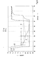
- FIG. 6 shows a time chart of the ⁇ values ⁇ M in front of the NO x storage catalytic converter and ⁇ K after the NO x storage catalytic converter during a regeneration phase of the NO x storage catalytic converter of the gasoline engine according to FIG. 5.
- the ⁇ M value is abruptly changed from a lean value of 1.45 to a rich value of 0.76 at a predetermined time.
- the regeneration phase of FIG. 6 lasts five seconds, after which the ⁇ M value is restored to the original lean value of 1.45.
- phase 1 a complete conversion of the offered reducing agent (CO, HC), which is why the value of ⁇ K is just above 1.
- phase 2 there is a slower reaction of the reducing agent offered and thus a breakthrough of HC and CO.
- phase 3 the reaction of the reducing agent offered is decayed, accompanied by a decrease in the ⁇ K value to the ⁇ M value. Accordingly, in this phase, the exhaust gas-harmful HC / CO breakthrough increases sharply.
- the present invention is based on the finding that a ⁇ K run would be desirable, as indicated in FIG. 6 by the dashed line S2 and approximately constant at ⁇ K approximately equal to 1 until the end of the regeneration phase.
- a corresponding course of the ⁇ M value is shown in FIG. 6 by the dot-dash line S1.
- the ⁇ M value is raised in front of the NO x storage catalyst with onset of the slower conversion of the offered reducing agent to counteract the HC / CO breakdown and the associated decrease in the ⁇ K value ,
- An object of the present invention is therefore to provide a method and an apparatus for controlling the mixture composition for a gasoline engine with NO x storage catalyst during a regeneration phase, which also in aged or poisoned NO x storage catalysts no increased CO and HC emissions entail.
- the inventive method for controlling the mixture composition for a gasoline engine with NO x storage catalyst during a regeneration phase according to claim 1 and the corresponding apparatus according to claim 8 have the advantage that an inventively designed or operated system the properties of different catalyst coatings or different aging - or sulfur poisoning conditions automatically adapts. From the control behavior can also draw conclusions about the state of the storage catalytic converter, so that information on sulfur regeneration requirements or for diagnostic purposes can be derived.
- the idea underlying the present invention is that the ⁇ M value of the exhaust gas supplied to the NO x storage catalytic converter in the course of the regeneration phase in a closed loop in the direction of a ⁇ K value of the exhaust gas emitted by the NO x storage catalytic converter Value of one is back-regulated.
- the control in the direction of the value of one preferably starts at a predetermined intervention value ⁇ i .
- the invention preferably provides for the use of a commercially available NO x sensor downstream of the NO x storage catalytic converter which, in addition to the NO x concentration, also measures the ⁇ k of the exhaust gas.
- control is set up such that the ⁇ K value of the exhaust gas ejected from the NO x storage catalytic converter does not fall below a value of one or only insignificantly.
- the regeneration phase is initiated when the NO x content of the exhaust gas ejected from the NO x storage catalytic converter exceeds a predetermined value.
- the regeneration phase is ended when the signal of an NO x sensor downstream of the NO x storage catalytic converter and / or its gradient exceeds a predetermined value.
- the NH 3 cross sensitivity of an NO x sensor can be used downstream of the NO x storage catalyst, which announces the completion of memory regeneration considerably before the ⁇ K signal. It makes sense to detect the end of the regeneration not only via the threshold value of the NO x signal (NH 3 signal), but also its slope.
- the regeneration phase is ended when the ⁇ K value of the exhaust gas ejected from the NO x storage catalytic converter falls below a predetermined value.
- this approach is less effective because of a long gas flow time between combustion chamber (reductant production) and measurement location (downstream NO x storage catalyst).
- the ⁇ M value of the exhaust gas supplied to the NO x storage catalytic converter is regulated at the beginning of the regeneration phase to a constant pilot control value ⁇ REG and the control in the direction of the value of one is not started until the ⁇ k value of the Exhaust gas emitted from the NO x storage catalyst falls below a predetermined intervention value ⁇ i . It has proven to be favorable to use the signal of the near-net ⁇ probe with a pre-control value 0.76 ⁇ REG ⁇ 1 adapted to the regeneration task in order to ensure the required regulating speed and accuracy in order to regulate the mixture composition.
- the ⁇ M value is modified according to the progress of the regeneration by a predetermined fixed or adaptive algorithm.
- the constant pilot control value ⁇ REG is obtained by carrying out a predetermined post-injection and controlling the ⁇ value of the main combustion such that the ⁇ M value of the exhaust gas supplied to the NO x storage catalytic converter assumes the constant pilot control value ⁇ REG ,
- the provision of the required reducing agent can be effected both by superfatting the combustion used for generating the power of the internal combustion engine (main combustion) and by post-injection.
- reducing agent by means of super-rich main combustion (0.76 ⁇ M ⁇ 1.0)
- preference is given to producing CO in the case of reducing agent addition by means of post-injection preferably HC as reducing agent.
- NO x which predominantly consists of NO (nitrogen monoxide)
- this NO x breakthrough does not arise or at least significantly reduced.
- the cause lies in the competitive situation that exists during phase 1 between NO x storage and O 2 storage of the catalysts. Only when the O 2 reservoirs are emptied can CO NO x be reliably reduced to N 2 .
- This embodiment therefore proposes during phase 1 of the regeneration to adjust the HC content of the exhaust gas by means of post-injection to, for example, a value of> 3000 ppm upstream of the NO x storage catalyst and to regenerate phases 2 and 3 by enriching the main combustion and thereby To fix the value of the main combustion. This is advantageous because high concentrations of HC are no longer reacted with progressive regeneration and lead to HC breakthroughs.
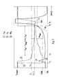
- FIG. 1 is a time chart of the ⁇ values ⁇ M in front of the NO x storage catalytic converter and ⁇ K after the NO x storage catalytic converter and the signal of the NO x sensor 10b during a regeneration phase of the NO x storage catalytic converter of the gasoline engine according to FIG. 5 for explaining an embodiment of the method according to the invention.
- the ⁇ -value ⁇ M of the main combustion at the time t 1 of a lean value ⁇ lean is abruptly set to a rich pilot value ⁇ Reg of, for example, 0.76 and held constant there until time t 2 .
- the value ⁇ K is also detected by the sensor 10b behind the NO x storage catalytic converter 5.
- the NO x signal detected by the sensor 10 b shows after the beginning of the regeneration phase a so-called desorption peak value DP, which is due to the fact that preferably CO is used as reducing agent in phase 1, ie until the intervention value ⁇ i is reached , by enriching the main combustion.
- the NO x signal drops sharply again. Only at the end of the regeneration phase, due to the NH 3 cross sensitivity of the sensor 10b, does the NO x signal strongly increase again and reach a slope SN at a value TNH at the time t 3 .
- the ⁇ value ⁇ M of the main combustion is reset to the value ⁇ lean again, which ends the regeneration phase.
- Another possibility to end the regeneration phase would be the detection of the decrease in the ⁇ K value after the end of the regeneration, in particular the setting of a threshold value T ⁇ for the ⁇ K value, as also indicated in FIG.
- this is not very effective if there is a long gas running time between the combustion chamber, that is to say the space of the reducing agent generation, and the measuring location of the sensor 10b downstream of the NO x storage catalytic converter 5.
- the system for controlling the mixture composition during the regeneration phase can be automatically adapted to aging and / or sulfur poisoning conditions.
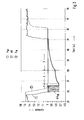
- FIG. 2 is a timing diagram of the ⁇ values ⁇ M in front of the NO x storage catalyst and ⁇ K after the NO x storage catalyst in a regeneration phase of the NO x storage catalytic converter of the gasoline engine according to FIG. 5 to explain a further embodiment of the method according to the invention.
- the reducing agent addition in phase 1 takes place by a post-injection NI.
- the constant pilot value ⁇ REG is obtained by performing the predetermined post-injection NI and controlling the ⁇ -value of the main combustion so that the ⁇ M value of the exhaust gas supplied to the NO x storage catalyst 5 is the constant pilot value ⁇ REG until the intervention value ⁇ i is reached by ⁇ K.
- FIG. 3 is an illustration for explaining regeneration with the main combustion
- Fig. 4 is an illustration for explaining a regeneration with a post-injection.
- the conclusion of the memory regeneration can be detected here even more simply by monitoring the rise of the NO x signal as a result of the NH 3 cross sensitivity of the sensor 10b.
Landscapes
- Engineering & Computer Science (AREA)
- Chemical & Material Sciences (AREA)
- Combustion & Propulsion (AREA)
- Mechanical Engineering (AREA)
- General Engineering & Computer Science (AREA)
- Chemical Kinetics & Catalysis (AREA)
- Exhaust Gas After Treatment (AREA)
Applications Claiming Priority (2)
| Application Number | Priority Date | Filing Date | Title |
|---|---|---|---|
| DE10139992 | 2001-08-16 | ||
| DE10139992A DE10139992B4 (de) | 2001-08-16 | 2001-08-16 | Verfahren zur Regelung der Gemischzusammensetzung für einen Ottomotor mit NOx-Speicherkatalysator während einer Regenerationsphase |
Publications (3)
| Publication Number | Publication Date |
|---|---|
| EP1284351A2 true EP1284351A2 (fr) | 2003-02-19 |
| EP1284351A3 EP1284351A3 (fr) | 2004-06-16 |
| EP1284351B1 EP1284351B1 (fr) | 2006-12-27 |
Family
ID=7695475
Family Applications (1)
| Application Number | Title | Priority Date | Filing Date |
|---|---|---|---|
| EP02015987A Expired - Lifetime EP1284351B1 (fr) | 2001-08-16 | 2002-07-18 | Procédé et dispositif de réglage de la composition du mélange d'un moteur à allumage comandé avec un catalyseur à accumulateur de NOx pendant le cycle de régénération |
Country Status (3)
| Country | Link |
|---|---|
| US (1) | US6871492B2 (fr) |
| EP (1) | EP1284351B1 (fr) |
| DE (2) | DE10139992B4 (fr) |
Cited By (1)
| Publication number | Priority date | Publication date | Assignee | Title |
|---|---|---|---|---|
| WO2007041092A3 (fr) * | 2005-09-29 | 2007-10-04 | Honeywell Int Inc | Utilisation de detecteurs dans un observateur de l'etats d'un moteur diesel |
Families Citing this family (24)
| Publication number | Priority date | Publication date | Assignee | Title |
|---|---|---|---|---|
| WO2003055638A1 (fr) | 2001-12-24 | 2003-07-10 | Digimarc Id Systems, Llc | Elements de securite grave au laser destines a des documents d'identification et procedes de fabrication de ces elements |
| US7694887B2 (en) | 2001-12-24 | 2010-04-13 | L-1 Secure Credentialing, Inc. | Optically variable personalized indicia for identification documents |
| ATE552120T1 (de) | 2001-12-24 | 2012-04-15 | L 1 Secure Credentialing Inc | Verdeckte variableninformationen auf id- dokumenten und verfahren zu ihrer herstellung |
| US7815124B2 (en) | 2002-04-09 | 2010-10-19 | L-1 Secure Credentialing, Inc. | Image processing techniques for printing identification cards and documents |
| US7824029B2 (en) | 2002-05-10 | 2010-11-02 | L-1 Secure Credentialing, Inc. | Identification card printer-assembler for over the counter card issuing |
| US7804982B2 (en) | 2002-11-26 | 2010-09-28 | L-1 Secure Credentialing, Inc. | Systems and methods for managing and detecting fraud in image databases used with identification documents |
| FR2849105B1 (fr) * | 2002-12-18 | 2007-03-16 | Renault Sa | Procede de commande d'un moteur a combustion interne pour la regeneration de moyens de purification des gaz d'echappement et dispositif associe |
| DE602004030434D1 (de) | 2003-04-16 | 2011-01-20 | L 1 Secure Credentialing Inc | Dreidimensionale datenspeicherung |
| US7018442B2 (en) * | 2003-11-25 | 2006-03-28 | Caterpillar Inc. | Method and apparatus for regenerating NOx adsorbers |
| DE10355037B4 (de) * | 2003-11-25 | 2013-10-10 | Robert Bosch Gmbh | Verfahren zum Optimieren der Abgaswerte einer Brennkraftmaschine |
| JP4349119B2 (ja) * | 2003-12-19 | 2009-10-21 | いすゞ自動車株式会社 | 排気ガス浄化方法及び排気ガス浄化システム |
| BRPI0511863A (pt) * | 2004-06-08 | 2008-01-15 | Cummins Inc | método para modificar o nìvel de disparo para regeneração de adsorvente |
| US7168243B2 (en) * | 2005-03-07 | 2007-01-30 | Caterpillar Inc | NOx adsorber and method of regenerating same |
| US7594392B2 (en) * | 2006-11-07 | 2009-09-29 | Cummins, Inc. | System for controlling adsorber regeneration |
| US7533523B2 (en) * | 2006-11-07 | 2009-05-19 | Cummins, Inc. | Optimized desulfation trigger control for an adsorber |
| US7707826B2 (en) * | 2006-11-07 | 2010-05-04 | Cummins, Inc. | System for controlling triggering of adsorber regeneration |
| US7654076B2 (en) * | 2006-11-07 | 2010-02-02 | Cummins, Inc. | System for controlling absorber regeneration |
| US7654079B2 (en) * | 2006-11-07 | 2010-02-02 | Cummins, Inc. | Diesel oxidation catalyst filter heating system |
| DE102007046353B3 (de) * | 2007-09-27 | 2009-04-16 | Continental Automotive Gmbh | Regenerationsverfahren für einen Speicherkatalysator |
| FR2926592B1 (fr) * | 2008-01-18 | 2012-07-13 | Peugeot Citroen Automobiles Sa | Procede d'injection d'agent reducteur dans une ligne d'echappement |
| US8701390B2 (en) * | 2010-11-23 | 2014-04-22 | International Engine Intellectual Property Company, Llc | Adaptive control strategy |
| DE102016218794A1 (de) | 2016-09-29 | 2018-03-29 | Robert Bosch Gmbh | Stationärer Erdgasmotor mit wenigstens einem Stickoxidsensor |
| DE102016015082A1 (de) | 2016-12-17 | 2018-06-21 | Daimler Ag | Verfahren zum Betreiben einer Abgasanlage eines Kraftwagens und Abgasanlage |
| US10920645B2 (en) | 2018-08-02 | 2021-02-16 | Ford Global Technologies, Llc | Systems and methods for on-board monitoring of a passive NOx adsorption catalyst |
Family Cites Families (16)
| Publication number | Priority date | Publication date | Assignee | Title |
|---|---|---|---|---|
| EP0598917B2 (fr) * | 1992-06-12 | 2009-04-15 | Toyota Jidosha Kabushiki Kaisha | Systeme de limitation d'emission de gaz d'echappement pour moteur a combustion interne |
| US5771685A (en) * | 1996-10-16 | 1998-06-30 | Ford Global Technologies, Inc. | Method for monitoring the performance of a NOx trap |
| DE19644407C2 (de) * | 1996-10-25 | 1999-09-23 | Daimler Chrysler Ag | Verfahren zur Reduzierung der Emissionen einer Brennkraftmaschine |
| US6105365A (en) * | 1997-04-08 | 2000-08-22 | Engelhard Corporation | Apparatus, method, and system for concentrating adsorbable pollutants and abatement thereof |
| DE59803438D1 (de) * | 1997-06-03 | 2002-04-25 | Siemens Ag | VERFAHREN ZUR REGENERATION EINES NOx-SPEICHERKATALYSATORS |
| JP3709655B2 (ja) * | 1997-06-09 | 2005-10-26 | 日産自動車株式会社 | 内燃機関の排気浄化装置 |
| DE19747222C1 (de) * | 1997-10-25 | 1999-03-04 | Daimler Benz Ag | Verbrennungsmotoranlage mit Stickoxid-Speicherkatalysator und Betriebsverfahren hierfür |
| DE19801815A1 (de) * | 1998-01-19 | 1999-07-22 | Volkswagen Ag | Mager-Regeneration von NOx-Speichern |
| JP3456401B2 (ja) * | 1998-02-12 | 2003-10-14 | 日産自動車株式会社 | 内燃機関の排気浄化装置 |
| DE19816276C2 (de) * | 1998-04-11 | 2000-05-18 | Audi Ag | Verfahren und Vorrichtung zum Betreiben einer Brennkraftmaschine |
| DE19823923C2 (de) * | 1998-05-28 | 2003-04-17 | Siemens Ag | Verfahren zur Stickoxidreduzierung im Abgas einer Brennkraftmaschine |
| DE19824915C1 (de) * | 1998-06-04 | 1999-02-18 | Daimler Benz Ag | Verfahren zum Wechseln der Betriebsart einer direkt-einspritzenden Otto-Brennkraftmaschine |
| DE19843879C2 (de) * | 1998-09-25 | 2003-05-08 | Bosch Gmbh Robert | Betrieb eines Verbrennungsmotors in Verbindung mit einem NOx-Speicherkatalysator und einem NOx-Sensor |
| DE19851843B4 (de) * | 1998-11-10 | 2005-06-09 | Siemens Ag | Verfahren zur Sulfatregeneration eines NOx-Speicherkatalysators für eine Mager-Brennkraftmaschine |
| DE19910664A1 (de) * | 1999-03-11 | 2000-09-14 | Volkswagen Ag | Verfahren zur De-Sulfatierung eines NOx-Speicherkatalysators |
| IT1310465B1 (it) * | 1999-09-07 | 2002-02-18 | Magneti Marelli Spa | Metodo autoadattativo di controllo di un sistema di scarico per motori a combustione interna ad accensione comandata. |
-
2001
- 2001-08-16 DE DE10139992A patent/DE10139992B4/de not_active Expired - Fee Related
-
2002
- 2002-07-18 DE DE50209061T patent/DE50209061D1/de not_active Expired - Fee Related
- 2002-07-18 EP EP02015987A patent/EP1284351B1/fr not_active Expired - Lifetime
- 2002-08-15 US US10/218,903 patent/US6871492B2/en not_active Expired - Fee Related
Cited By (1)
| Publication number | Priority date | Publication date | Assignee | Title |
|---|---|---|---|---|
| WO2007041092A3 (fr) * | 2005-09-29 | 2007-10-04 | Honeywell Int Inc | Utilisation de detecteurs dans un observateur de l'etats d'un moteur diesel |
Also Published As
| Publication number | Publication date |
|---|---|
| EP1284351B1 (fr) | 2006-12-27 |
| EP1284351A3 (fr) | 2004-06-16 |
| DE50209061D1 (de) | 2007-02-08 |
| DE10139992B4 (de) | 2006-04-27 |
| US6871492B2 (en) | 2005-03-29 |
| US20030056500A1 (en) | 2003-03-27 |
| DE10139992A1 (de) | 2003-03-06 |
Similar Documents
| Publication | Publication Date | Title |
|---|---|---|
| EP1284351B1 (fr) | Procédé et dispositif de réglage de la composition du mélange d'un moteur à allumage comandé avec un catalyseur à accumulateur de NOx pendant le cycle de régénération | |
| DE60303867T2 (de) | Vorrichtung und Verfahren zur Schwefelentgiftung eines Katalysators einer Dieselbrennkraftmaschine | |
| DE102015223934A1 (de) | System und Verfahren zur Abgasreinigung mittels Mager-NOx-Falle (LNT) und Katalysator mit selektiver katalytischer Reduktion | |
| DE102016209566A1 (de) | Steuern einer Stickoxidemission im Abgas einer Brennkraftmaschine | |
| EP3412880A1 (fr) | Methode de regeneration d'un filtre a particules dans l'echappement d'un moteur de combustion interne | |
| DE10126455B4 (de) | Verfahren zur Desulfatisierung eines Stickoxid-Speicherkatalysators | |
| DE102016112657A1 (de) | Verfahren und Vorrichtung zur Abgasnachbehandlung eines Verbrennungsmotors | |
| EP1192343B1 (fr) | PROCEDE PERMETTANT DE LANCER ET DE SURVEILLER LA DESULFURATION D'AU MOINS UN CATALYSEUR A STOCKAGE DE NOx PLACE DANS UN TUYAU D'ECHAPPEMENT D'UN MOTEUR A COMBUSTION INTERNE | |
| DE102017115399A1 (de) | Abgasnachbehandlungssystem und Verfahren zur Abgasnachbehandlung eines Verbrennungsmotors | |
| EP1106798B1 (fr) | Dispositif et procédé pour NOx- et/ou SOx régénération d'un catalyseur accumulateur de NOx | |
| DE10115967B4 (de) | Verfahren und eine Vorrichtung zur Nachbehandlung eines Abgases | |
| DE102017201401B4 (de) | Abgasnachbehandlung | |
| DE10361791A1 (de) | Vorrichtung zur Reinigung des Abgases einer Brennkraftmaschine und Verfahren zur Regeneration einer solchen Abgasreinigungsanlage | |
| EP1204815B1 (fr) | Procede de reglage de la temperature des gaz d'echappement d'un moteur a combustion interne a melange pauvre pendant une desulfuration d'un catalyseur | |
| EP1179124B1 (fr) | Procede de desulfuration | |
| EP1052382B1 (fr) | Purification de gaz d'échappement comprenant un catalyseur de stockage de NOx et un pré-catalyseur | |
| EP1099465B1 (fr) | Procédé et dispositif pour purifier le gaz d'échappement d'un moteur à combustion interne | |
| DE10153901A1 (de) | Verfahren und Vorrichtung zur Entschwefelung eines einem Dieselmotor nachgeschalteten NOx-Speicherkatalysators | |
| EP1252420B1 (fr) | Dispositif et procede de commande d'une regeneration de nox d'un catalyseur accumulateur de nox | |
| DE10010031B4 (de) | Verfahren und Vorrichtung zur Durchführung einer NOx-Regeneration eines in einem Abgaskanal einer Verbrennungskraftmaschine angeordneten NOx-Speicherkatalysators | |
| DE102017101610A1 (de) | Verfahren zur Reduzierung der Kaltstart-Emissionen bei einem fremdgezündeten Verbrennungsmotor | |
| DE102017201399B4 (de) | Abgasnachbehandlungssystem | |
| EP1188915B1 (fr) | Procédé de réglage de la régénération d'un catalyseur d'accumulation de NOx | |
| EP1365131B1 (fr) | Procédé de reglage d'un catalyseur d'accumulation de NOx | |
| DE102004052062A1 (de) | Verfahren und Vorrichtung zur Regenerierung von Speicherkatalysatoren |
Legal Events
| Date | Code | Title | Description |
|---|---|---|---|
| PUAI | Public reference made under article 153(3) epc to a published international application that has entered the european phase |
Free format text: ORIGINAL CODE: 0009012 |
|
| AK | Designated contracting states |
Designated state(s): AT BE BG CH CY CZ DE DK EE ES FI FR GB GR IE IT LI LU MC NL PT SE SK TR |
|
| AX | Request for extension of the european patent |
Extension state: AL LT LV MK RO SI |
|
| PUAL | Search report despatched |
Free format text: ORIGINAL CODE: 0009013 |
|
| AK | Designated contracting states |
Kind code of ref document: A3 Designated state(s): AT BE BG CH CY CZ DE DK EE ES FI FR GB GR IE IT LI LU MC NL PT SE SK TR |
|
| AX | Request for extension of the european patent |
Extension state: AL LT LV MK RO SI |
|
| RIC1 | Information provided on ipc code assigned before grant |
Ipc: 7F 02D 41/02 A Ipc: 7F 02D 41/14 B |
|
| 17P | Request for examination filed |
Effective date: 20041216 |
|
| AKX | Designation fees paid |
Designated state(s): DE FR GB IT |
|
| GRAP | Despatch of communication of intention to grant a patent |
Free format text: ORIGINAL CODE: EPIDOSNIGR1 |
|
| GRAS | Grant fee paid |
Free format text: ORIGINAL CODE: EPIDOSNIGR3 |
|
| GRAA | (expected) grant |
Free format text: ORIGINAL CODE: 0009210 |
|
| AK | Designated contracting states |
Kind code of ref document: B1 Designated state(s): DE FR GB IT |
|
| REG | Reference to a national code |
Ref country code: GB Ref legal event code: FG4D Free format text: NOT ENGLISH |
|
| REF | Corresponds to: |
Ref document number: 50209061 Country of ref document: DE Date of ref document: 20070208 Kind code of ref document: P |
|
| GBT | Gb: translation of ep patent filed (gb section 77(6)(a)/1977) |
Effective date: 20070319 |
|
| RAP2 | Party data changed (patent owner data changed or rights of a patent transferred) |
Owner name: VOLKSWAGEN AG Owner name: BAYERISCHE MOTOREN WERKE AKTIENGESELLSCHAFT Owner name: DAIMLERCHRYSLER AG Owner name: DR.ING. H.C.F. PORSCHE AKTIENGESELLSCHAFT Owner name: AUDI AG |
|
| ET | Fr: translation filed | ||
| PLBE | No opposition filed within time limit |
Free format text: ORIGINAL CODE: 0009261 |
|
| STAA | Information on the status of an ep patent application or granted ep patent |
Free format text: STATUS: NO OPPOSITION FILED WITHIN TIME LIMIT |
|
| 26N | No opposition filed |
Effective date: 20070928 |
|
| REG | Reference to a national code |
Ref country code: FR Ref legal event code: TQ |
|
| PGFP | Annual fee paid to national office [announced via postgrant information from national office to epo] |
Ref country code: FR Payment date: 20090716 Year of fee payment: 8 |
|
| REG | Reference to a national code |
Ref country code: FR Ref legal event code: CD |
|
| PGFP | Annual fee paid to national office [announced via postgrant information from national office to epo] |
Ref country code: DE Payment date: 20090722 Year of fee payment: 8 Ref country code: GB Payment date: 20090720 Year of fee payment: 8 |
|
| PGFP | Annual fee paid to national office [announced via postgrant information from national office to epo] |
Ref country code: IT Payment date: 20090728 Year of fee payment: 8 |
|
| GBPC | Gb: european patent ceased through non-payment of renewal fee |
Effective date: 20100718 |
|
| REG | Reference to a national code |
Ref country code: GB Ref legal event code: 732E Free format text: REGISTERED BETWEEN 20110310 AND 20110316 |
|
| REG | Reference to a national code |
Ref country code: FR Ref legal event code: ST Effective date: 20110331 |
|
| REG | Reference to a national code |
Ref country code: GB Ref legal event code: 732E Free format text: REGISTERED BETWEEN 20110331 AND 20110406 |
|
| PG25 | Lapsed in a contracting state [announced via postgrant information from national office to epo] |
Ref country code: DE Free format text: LAPSE BECAUSE OF NON-PAYMENT OF DUE FEES Effective date: 20110201 |
|
| REG | Reference to a national code |
Ref country code: DE Ref legal event code: R119 Ref document number: 50209061 Country of ref document: DE Effective date: 20110201 |
|
| PG25 | Lapsed in a contracting state [announced via postgrant information from national office to epo] |
Ref country code: FR Free format text: LAPSE BECAUSE OF NON-PAYMENT OF DUE FEES Effective date: 20100802 Ref country code: IT Free format text: LAPSE BECAUSE OF NON-PAYMENT OF DUE FEES Effective date: 20100718 |
|
| REG | Reference to a national code |
Ref country code: FR Ref legal event code: TQ |
|
| PG25 | Lapsed in a contracting state [announced via postgrant information from national office to epo] |
Ref country code: GB Free format text: LAPSE BECAUSE OF NON-PAYMENT OF DUE FEES Effective date: 20100718 |