EP1284525A2 - Steckverbinder - Google Patents
Steckverbinder Download PDFInfo
- Publication number
- EP1284525A2 EP1284525A2 EP02016916A EP02016916A EP1284525A2 EP 1284525 A2 EP1284525 A2 EP 1284525A2 EP 02016916 A EP02016916 A EP 02016916A EP 02016916 A EP02016916 A EP 02016916A EP 1284525 A2 EP1284525 A2 EP 1284525A2
- Authority
- EP
- European Patent Office
- Prior art keywords
- type connector
- plug type
- enclosure
- engaged
- arm portion
- Prior art date
- Legal status (The legal status is an assumption and is not a legal conclusion. Google has not performed a legal analysis and makes no representation as to the accuracy of the status listed.)
- Granted
Links
- 239000002184 metal Substances 0.000 claims abstract description 37
- 229920003002 synthetic resin Polymers 0.000 claims abstract description 27
- 239000000057 synthetic resin Substances 0.000 claims abstract description 27
- 238000005452 bending Methods 0.000 claims abstract description 8
- 239000000806 elastomer Substances 0.000 claims description 10
- 229920001971 elastomer Polymers 0.000 claims description 9
- 230000005489 elastic deformation Effects 0.000 claims description 3
- 238000013459 approach Methods 0.000 claims description 2
- 230000008878 coupling Effects 0.000 abstract description 3
- 238000010168 coupling process Methods 0.000 abstract description 3
- 238000005859 coupling reaction Methods 0.000 abstract description 3
- 230000014759 maintenance of location Effects 0.000 description 6
- 238000003825 pressing Methods 0.000 description 6
- 229920005989 resin Polymers 0.000 description 4
- 239000011347 resin Substances 0.000 description 4
- 230000001771 impaired effect Effects 0.000 description 3
- 238000006073 displacement reaction Methods 0.000 description 2
- 238000003780 insertion Methods 0.000 description 2
- 230000037431 insertion Effects 0.000 description 2
- 238000009434 installation Methods 0.000 description 2
- 238000000034 method Methods 0.000 description 2
- 230000002035 prolonged effect Effects 0.000 description 2
- 230000000717 retained effect Effects 0.000 description 2
- 229920003051 synthetic elastomer Polymers 0.000 description 2
- 238000004519 manufacturing process Methods 0.000 description 1
- 230000001737 promoting effect Effects 0.000 description 1
- 238000000638 solvent extraction Methods 0.000 description 1
- 239000005061 synthetic rubber Substances 0.000 description 1
Images


Classifications
-
- H—ELECTRICITY
- H01—ELECTRIC ELEMENTS
- H01R—ELECTRICALLY-CONDUCTIVE CONNECTIONS; STRUCTURAL ASSOCIATIONS OF A PLURALITY OF MUTUALLY-INSULATED ELECTRICAL CONNECTING ELEMENTS; COUPLING DEVICES; CURRENT COLLECTORS
- H01R13/00—Details of coupling devices of the kinds covered by groups H01R12/70 or H01R24/00 - H01R33/00
- H01R13/62—Means for facilitating engagement or disengagement of coupling parts or for holding them in engagement
- H01R13/627—Snap or like fastening
- H01R13/6271—Latching means integral with the housing
- H01R13/6273—Latching means integral with the housing comprising two latching arms
Definitions
- the present invention relates to a plug type connector, and more particularly to a plug type connector having a locking function of, when the connector is connected to a counter connector, coupling the connector to the counter connector.
- the level of the operation load which is required for flexurally deforming the locking piece can be increasingly or decreasingly adjusted.
- the enclosure of the counter connector is not shaved by a prying force applied on the counter connector, and hence the stability of the locked state can be enhanced.
- a measure for enabling such a plug type connector to be easily miniaturized is taken.
- Japanese Patent Application Laying-Open No. 2001-176620, Japanese Utility Model Application Laying-Open No. 6-19284, and U.S. Patent No. 6,071,141 disclose plug type connectors of this type.
- a spring plate configured by a sheet metal is employed as a locking member for exerting a locking function.
- a slender locking piece configured by a synthetic resin molded product which has the property of being bent more hardly than a sheet metal spring plate, as a locking member.
- the plug type connector of the invention of claims 1 to 6 comprises: a contact portion which is to be electrically connected to a counter connector; an elastic locking piece which is placed on each of both sides of the contact portion, and which is to be engaged with and disengaged from an engagement portion of the counter connector; and a press operating member which presses the locking piece positioned in a position of engagement with the engagement portion in a direction along which the locking piece approaches the contact portion, whereby the locking piece is displaced against resiliency to a position of disconnection from the engagement portion.
- the locking piece engaged with the engagement portion of the counter connector can be disconnected from the engagement portion by operating the press operating member.
- the locking piece can be returned by its resiliency to the position of engagement with the engagement portion of the counter connector.
- the connector has: the locking piece configured by a synthetic resin molded product having an elastic slender arm portion that is flexurally deformable, and a latch portion that is to be engaged with and disengaged from the engagement portion by means of flexural deformation of the arm portion; and a backup member which is placed behind the arm portion, and which has resiliency for adjusting a level of an operation load that is required for supporting and flexurally deforming the arm portion.
- the locking piece uses a synthetic resin molded product, and the synthetic resin molded product has the property of being bent more hardly than a metal. Even when the tip end of the locking piece configured by a synthetic resin molded product protrudes in front of an enclosure of the plug type connector to be exposed therefrom, therefore, accidental deformation does not occur.
- the level of the operation load that is required for flexurally deforming the arm portion of the locking piece can be adjusted simply by adjusting the degree of the resilient force of the backup member. Therefore, the level of a load which is required to be applied to the arm portion when the latch portion of the locking piece is to be engaged with the engagement portion of the counter connector, and that of a load which is required to be applied to the arm portion when the latch portion of the locking piece is to be disconnected from the engagement portion of the counter connector can be adjusted simply by adjusting the degree of the resilient force of the backup member. This means that an increase or decrease adjustment of the deformation load or the operation load does not require the necessity to adjust the length of the arm portion of the locking piece. Therefore, the levels of the loads can be changed without changing the whole size of the plug type connector.
- a half locked state where the connectors can be easily disengaged from each other, or a full locked state where the connectors cannot be disengaged from each other can be readily produced simply by adjusting the degree of the resilient force of the backup member.
- This function can be performed also by employing a configuration in which, as in the invention of claim 2, a deformation load which can flexurally deform the arm portion can be set to be smaller than the operation load, by selecting a thickness of the arm portion, and an insufficiency of the deformation load with respect to the operation load is compensated by a resilient force of the backup member.
- a plate piece-like synthetic resin molded product preferably, a plate piece-like elastomer is used in the backup member.
- the backup member has the function of adjusting the level of the operation load that is required for supporting and flexurally deforming the arm portion of the locking piece. From only this point of view, it is possible to use a sheet metal spring plate or a metal coil spring. When a sheet metal spring plate or a metal coil spring is used, however, a relatively large installation space is required, and moreover the spring itself is expensive, with the result that the size and cost of the plug type connector tend to be increased. By contrast, when a plate piece-like synthetic resin molded product is used in the backup member as in the invention, the required installation space is small, the cost is low, and hence the size and cost of the plug type connector can be easily reduced. When a plate piece-like elastomer is used in the backup member, particularly, there is an advantage that the backup member can be improved in durability and resiliency as compared with the case where a synthetic resin molded product is used.
- the degree of the resilient force of the backup member is defined by adjusting an area of a contact surface with respect to the arm portion.
- the contact portion and the locking piece are accommodated in a common enclosure
- the press operating member is attached to each of lateral sides of the enclosure
- the enclosure comprises: a wall face which overlaps with a back face of the backup member; and a concave or convex backup member holding portion to which the backup member is to be fitted or detached.
- the backup member can be placed so as to overlap with the wall face, and hence the backup member can surely perform the function of adjusting the operation load. Moreover, the backup member can be fitted into or detached from the concave or convex backup member holding portion. When the degree of the resilient force of the backup member is to be adjusted, therefore, backup members of different areas of the contact surface can be replaced with each other by an operation of fitting to the backup member holding portion. This is useful for promoting mass-production of the plug type connector.
- the level of the operation load required for flexurally deforming the locking piece can be adjusted without changing the deformation load possessed by the locking piece itself. Therefore, the level of the operation load required for flexurally deforming the locking piece can be adjusted without affecting the whole size of the plug type connector. As a result, the plug type connector can be easily miniaturized irrespective of the level of the operation load.
- a plug type connector can be economically provided in which the locked state where the locking piece is engaged with the engagement portion of the counter connector can be set to a half locked state or to a full locked state by using only an economical synthetic resin molded product, and without using a metal part such as a sheet metal spring plate or a metal coil spring.
- the plug type connector of the invention of claims 7 to 13 comprises: a contact portion which is to be electrically connected to a counter connector; and an elastic locking member which is placed on each of both sides of the contact portion, and which is to be engaged with an engagement portion of the counter connector in accordance with connection of the contact portion with the counter connector.
- the locking member is produced by bending a metal wire rod having a circular section shape.
- the metal wire rod forming the locking member has a circular section shape, and hence the locking member has no edge. Even when a prying force is applied during a work of connecting or disconnecting the plug type connector from the counter connector, therefore, a situation where the enclosure of the counter connector is shaved by an edge of the locking member does not occur. Since the locking member which is produced by bending a metal wire rod can be easily made smaller than that which is produced by using a plate spring or a resin molded product, miniaturization of the plug type connector comprising the locking member which is produced by using a metal wire rod is easily expedited.
- the locking member When the locking member is produced by bending a metal wire rod, the locking member is lower in cost than that which is produced by using a plate spring or a synthetic resin molded product because the metal wire rod itself is economical and a sophisticated process is not necessary. This is useful for reducing the cost of the plug type connector.
- the locking member comprises: an arm portion which is accommodated in an enclosure, in which a tip end portion protrudes in front of the enclosure, and which is elastically deformable; and a mountain-like engaged portion which is disposed on a tip end of the arm portion.
- the mountain-like engaged portion has: a front inclined part which is pressed from an outside against the engagement portion of the counter connector to cause the engaged portion to slide over the engagement portion to override the engagement portion and reach an inner side of the engagement portion, while elastically deforming the arm portion; and a rear inclined part which, when the engaged portion overrides the engagement portion and reaches the inner side of the engagement portion, cooperates with a butting surface of the enclosure to clampingly press the engagement portion.
- the front inclined part and the rear inclined part are inclined in opposite directions.
- the mountain-like engaged portion may be configured so that the front inclined part and the rear inclined part are linearly formed, or so that the front inclined part and the rear inclined part are formed into a continuous arcuate shape.
- the rear inclined part has an inclination which, when the enclosure is pulled in a direction along which the enclosure is separated from the engagement portion in a state where the rear inclined part cooperates with the butting surface to clampingly press the engagement portion, allows the rear inclined part to slide over the engagement portion to guide the engaged portion to an outside of the engagement portion while elastically deforming the arm portion.
- the plug type connector when the plug type connector is to be connected to the counter connector, it is requested to perform only an operation of pressing from the outside the mountain-like engaged portion against the engagement portion of the counter connector.
- the engagement portion of the counter connector is clampingly pressed by means of cooperation of the rear inclined part of the engaged portion and the butting surface of the enclosure, and hence the counter connector and the plug type connector are connected to each other in a rattle-free condition.
- This function is performed more satisfactorily because the locking member is produced by using a metal wire rod, and the rear inclined part of the engaged portion exerts the elasticity of the wire rod.
- the enclosure is formed into a flat shape
- the mountain-like engaged portion of the locking member is placed in a form in which the engaged portion protrudes from the arm portion in a thickness direction of the enclosure
- the enclosure has a guide face which restricts a direction of the elastic deformation of the arm portion to the thickness direction of the enclosure.
- the width of the engaged portion is limited to the thickness of the metal wire rod forming the engaged portion, and the direction of the swing of the engaged portion due to the elastic deformation of the arm portion is restricted only to the thickness direction of the enclosure. Therefore, it is not required to include the swing amplitude of the engaged portion in the width of the enclosure. Consequently, as compared with the connector which has been described in the beginning of the specification, and in which the locking member is formed by a resin molded product, the width of the enclosure can be reduced and miniaturization of the enclosure can be easily expedited.
- the arm portion is formed by a pair of parallel linear portions
- the rear inclined part of the mountain-like engaged portion is continuous to a tip end of one of the linear portions
- the front inclined part of the engaged portion is continuous to a tip end of the other linear portion.
- the pair of parallel linear portions forming the arm portion can be provided with elasticity of an adequate degree.
- the locking member is configured by a pair of bent wire rods each having the arm portion and the mountain-like engaged portion, and the wire rods are placed to overlap each other in the width direction of the enclosure in a state where the mountain-like engaged portions protrude in opposite directions.
- the linear portions of the other side are placed to overlap each other in the width direction of the enclosure.
- a metal wire rod having a circular section shape is used as the locking member, and, even when a prying force is applied during a work of connecting or disconnecting the plug type connector from the counter connector, therefore, a situation where the enclosure of the counter connector is shaved does not occur. Therefore, the stability of the locked state is enhanced. Since a metal wire rod is used as the locking member, miniaturization of the plug type connector is easily expedited. Even when a prying force is applied during a work of disconnecting the plug type connector from a counter connector connected thereto, the locking member is disengaged before the counter connector is broken, thereby preventing the counter connector from being broken. Moreover, according to the invention, the locking member can be economically produced, and hence the cost of the plug type connector can be easily reduced.
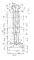
- Figs. 1 to 5 correspond to the plug type connector of the invention of claims 1 to 6.
- the plug type connector A has a laterally oblong flat enclosure 10 which is formed by a base portion 11 and a cover portion 12 combined with the base portion 11.
- the enclosure 10 many contact portions 20 which form contacts, and which are made of a sheet metal, locking pieces 30, 30 which are placed on both sides of a row of the contact portions 20, respectively, press operating members 50, 50 which are attached to the lateral sides of the enclosure 10, respectively, and a backup member 60 are disposed.
- the contact portions 20 ... and the locking pieces 30, 30 protrude in front of the front end face 13 of the enclosure 10.
- each of the locking pieces 30 comprises: an attachment portion 31 which is fitted into a rectangular recess 14 of the base portion 11 to be immovably held therein; an arm portion 32 which forward elongates from the attachment portion 31 in a longitudinally oblong recess 15 that is formed continuously to the recess 14; and a protruding latch portion 33 which is disposed on the front end of the arm portion 32 so as to be projected outward in the lateral direction.
- the latch portion 33 is formed into a tapered shape.
- the locking piece 30 is configured by an integral molded product of a synthetic resin, and the arm portion 32 is provided with flexurally deformable elasticity characteristic to the synthetic resin.
- the latch portion 33 has a thickness which prevents the portion from being easily chipped or broken by interference or collision with another article.
- the backup member 60 is formed by a plate piece-like elastomer, and has resiliency.
- the rear face overlaps a wall face 16 of the base portion 11, and a protrusion piece 61 formed in the lower end of the backup member 60 is fitted into a recessed backup member holding portion 18 which is formed in the lower wall 17 of the base portion 11. Therefore, the backup member 60 is positioned at a position where the member overlaps the wall face 16, by fitting of the protrusion piece 61 and the backup member holding portion 18.
- the surface of the backup member 60 which is positioned in this way overlaps the back face of the arm portion 32 of the locking piece 30 in an unloaded condition.
- the press operating members 50 are loosely fitted into recesses 19 which are formed in lateral end portions of the base portion 11, respectively, so as to be laterally extractable and retractable only in a constant range.
- the outer end face of each of the members is formed as a press operating face 51.
- a press working portion 52 which is opposed to the arm portion 32 of the locking piece 30 is formed on an inner end portion of the member.
- the locking pieces 30, the backup members 60, and the press operating members 50 are placed respectively in lateral end portions of the enclosure 10 in symmetrical relationships.
- Figs. 3 to 5 show a jack type connector B which is the counter connector.
- the illustrated jack type connector B has a recessed portion 110 into which the latch portion 33 of the locking piece 30 is to be fitted, in each of lateral end portions of a laterally oblong hollow enclosure 100; and an engagement portion 130 which is to be engaged with and disengaged from the latch portion 33 of the locking piece 30, in an edge of an opening 120 of the recessed portion 110. Between the right and left recessed portions 110, an opening into which the row of the contact portions 20 is to be inserted, and terminals (not shown) which are to be in contact with the row of the contact portions 20 are disposed.
- the tapered latch portion 33 of the locking piece 30 is pressingly inserted as indicated by the arrow a in a state where the latch portion butts against the edge 121 of the opening 120.
- the arm portion 32 is flexurally deformed in the laterally inward direction while compressing the backup member 60 against the resilient force of the member. This causes the latch portion 33 to override the edge 121 of the opening 120.
- the arm portion 32 When the latch portion 33 overrides the edge 121 of the opening 120 in this way, the arm portion 32 is returned to its initial position by the elasticity of the arm portion 32 itself and the resilient force of the backup member 60, so that the latch portion 33 is engaged with the engagement portion 130 as shown in Fig. 4.
- the row of the contact portions 20 is inserted into the jack type connector B and then contacted with the terminals of the connector. In this state, the plug type connector A is coupled with the jack type connector B by the engagement between the latch portion 33 and the engagement portion 130. This is the locked state.
- a synthetic resin molded product is used as the locking piece 30. Even when the latch portion 33 of the locking piece 30 protrudes in front of the enclosure 10 to be exposed therefrom, or when the latch portion 33 accidentally interferes with any other article to impact thereagainst, therefore, a situation where the latch portion 33 is bent, chipped, or broken hardly occurs.
- the press operating member 50 is pressingly inserted by a finger of the hand as indicated by the arrow P of Fig. 5.
- the press working portion 52 presses the arm portion 32 of the locking piece 30 in the laterally inward direction. Therefore, the arm portion 32 is flexurally deformed in the laterally inward direction against the elasticity of the portion and the resilient force of the backup member 60. In accordance with this deformation, the latch portion 33 is displaced from the position of engagement with the engagement portion 130, toward the inner side in the lateral direction.
- the latch portion 33 When the latch portion 33 is disconnected from the engagement portion 130 in this way, the coupling state of the plug type connector A and the jack type connector B is cancelled, and hence the plug type connector A can be pulled out from the jack type connector B.
- the arm portion 32 When the plug type connector A is pulled out from the jack type connector B, the arm portion 32 is returned to the initial position by the elasticity of the arm portion 32 itself and the resilient force of the backup member 60.
- the latch portion 33 is formed into a tapered shape.
- the latch portion 33 is pressingly inserted while being pressed against the edge 121 of the opening 120 as shown in Fig. 3, therefore, the latch portion 33 is caused by the guiding function of the surface of the latch portion 33 to override the edge 121 while flexurally deforming the arm portion 32, and then fitted into the recessed portion 110 as shown in Fig. 4.
- the press operating member 50 is pressed to slightly displace the latch portion 33 in the laterally inward direction as shown in Fig. 5 and the plug type connector A is then pulled, the latch portion 33 is caused by the guiding function of the surface of the latch portion 33 to override the edge 121 while flexurally deforming the arm portion 32, and then disconnected from the engagement portion 130.
- the degree of the pressing force which is required for pressingly inserting the latch portion 33 of the locking piece 30 into the recessed portion 110 and engaging the latch portion with the engagement portion 130 (hereinafter, such a force is referred to as latch portion pressing force) is defined by the degree of the elasticity of the arm portion 32 and that of the resilient force of the backup member 60. This is similarly applicable also to the operating force of the press operating member 50 which is exerted when the press operating member 50 is pressingly inserted to flexurally deform the arm portion 32 (hereinafter, such a force is referred to as operating member operating force).
- a load required for flexurally deforming the arm portion 32 against the elasticity of the arm portion itself is defined as deformation load
- that required for flexurally deforming the arm portion 32 against the elasticity of the arm portion itself and the resiliency of the backup member 60 is defined as operation load.
- the operation load can be adjusted simply by changing the resiliency of the backup member 60 while the elasticity of the arm portion 32 is unchanged.
- the degree of the resilient force of the backup member 60 can be controlled by adjusting the area of a contact surface of the backup member 60 with respect to the arm portion 32. The area of the contact surface is changed simply by changing the width W of the backup member 60 shown in Fig. 4.
- the operation load can be adequately adjusted simply by replacing the plate piece-like backup member 60 with another one to change the size of the member, and without changing the length of the arm portion 32 of the locking piece 30. While the deformation load is reduced by thinning the arm portion 32, the insufficiency of the operation load can be compensated by the resilient force of the backup member 60. Therefore, a half locked state where, when the plug type connector A is forcibly pulled under the situation where the plug type connector A is coupled to the jack type connector B as shown in Fig. 4, the connectors A, B are disengaged from each other, or a full locked state where the connectors A, B are not disengaged from each other can be readily produced simply by adjusting the degree of the resilient force of the backup member 60.
- a plate piece-like elastomer is used in the backup member 60.
- the member may be formed by a synthetic resin molded product as seen in usual synthetic rubber which is more economical than elastomer. In order to enhance the durability and obtain preferable resiliency, it is desirable to use elastomer.
- each of the locking pieces 30 is configured by an integral molded product of a synthetic resin
- the backup member 60 is formed by a plate piece-like elastomer, and the operation load can be adjusted by replacing only the backup member 60 and without replacing the locking pieces 30. Therefore, plug type connectors of different operation loads can be easily mass-produced.
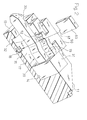
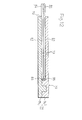
- Figs. 6 to 16 correspond to the plug type connector of the invention of claims 7 to 13.
- elements which are identical or correspond to those of Figs. 1 to 5 are denoted by the same reference numerals.
- the plug type connector A comprises, in the laterally oblong flat enclosure 10 which is formed by the base portion 11 and the cover portion 12 combined with the base portion, the many contact portions 20 which form contacts, and which are made of a sheet metal, and lock units 70, 70 which are placed on both sides of the row of the contact portions 20, respectively.
- the contact portions 20 ..., and locking members 80, 80 which are disposed on the lock units 70, 70 protrude in front of the front end face 13 of the enclosure 10.
- the front end face of a case 71 of each of the lock units 70 is flush with the front end face 13 of the enclosure 10, and is formed as a butting surface 72 of the enclosure.
- each of the locking members 80 comprises a pair of bent wire rods 81, 81 which are produced by bending a thin metal wire rod having a circular section shape.
- Each of the bent wire rods 81 integrally comprises: a pair of parallel long linear portions 82a, 82b forming an arm portion 82; a mountain-like engaged portion 84 which is connected to the tip ends of the linear portions 82a, 82b; and latch portions 85, 85 which are bendingly formed in basal areas of the linear portions 82a, 82b, respectively.
- the mountain-like engaged portion 84 comprises a linear front inclined part 86 which is forward and downward inclined, and a rear inclined part 88 which is forward and upward inclined and smoothly continuous to the front inclined part 86 via a curved part 87.
- the rear inclined part 88 is smoothly continuously connected to the tip end of the one linear portion 82a via a curved part 89, and the front inclined part 86 is smoothly continuously connected to the tip end of the other linear portion 82b.
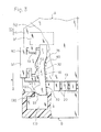
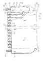
- the case 71 of each of the lock units 70 has a split structure which is formed by laterally combining a base 74 with a cover 75.
- formed are: a latch groove 76 which elongates in the longitudinal direction; three retention grooves 77, 78, 79 which forward elongate in parallel from the latch groove 76; and a flat guide face 73 which is formed by a recessed face formed in front of the retention grooves 77, 78, 79.
- the pair of linear portions 82a, 82b of the one bent wire rod 81 forming the locking member 80 are fitted in a rattle-free condition into the lower two retention grooves 77, 78 which are adjacent to each other, to be retained thereby.
- the two latch portions 85, 85 of the bent wire rod 81 are fitted into the latch groove 76 to be held so as not to longitudinally rattle.
- the pair of linear portions 82a, 82b which elongate from the latch portions 85, 85 are in contact with the guide face 73 so as to be vertically slidable. Tip end portions of the linear portions 82a, 82b protrude together with the mountain-like engaged portion 84, in front of the butting surface 72 which is formed by the front end face of the case 71.
- the pair of linear portions 82a, 82b of the other bent wire rod 81 forming the locking member 80 are fitted in a rattle-free condition into the upper two retention grooves 78, 79 which are adjacent to each other, to be retained thereby.
- the two latch portions of the bent wire rod 81 are fitted into the latch groove 76 to be held so as not to longitudinally rattle.
- the pair of linear portions 82a, 82b which elongate from the latch portions are in contact with the guide face 73 so as to be vertically slidable. Tip end portions of the linear portions 82a, 82b protrude together with the mountain-like engaged portion 84, in front of the butting surface 72 which is formed by the front end face of the case 71.
- the linear portions 82b, 82b of the other one of the paired bent wire rods 81 are placed so as to overlap each other in the width direction of the enclosure 10 (see Fig. 6).
- the linear portions 82b, 82b are overlappingly placed between the right and left guide faces 73.
- the mountain-like engaged portion 84 of the lower bent wire rod 81 protrudes downward in the thickness direction of the enclosure 10 shown in Fig. 6, and the mountain-like engaged portion 84 of the upper bent wire rod 81 protrudes upward in the thickness direction of the enclosure 10 shown in Fig. 6.
- a space which strainlessly enables the above-mentioned displacement of the arm portion 82 in the vertical direction (the thickness direction of the enclosure 10) is ensured.
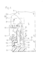
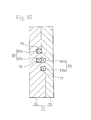
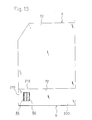
- Fig. 13 shows the jack type connector B which is the counter connector.
- an insertion space (not shown) into which the row of the contact portions 20 of the plug type connector A is to be inserted, and terminals (not shown) which are to be in contact with the row of the contact portions 20 are disposed in a laterally oblong hollow enclosure 200.
- Lock portions 210 are disposed on both the lateral sides of the insertion space, respectively.
- the engaged portions 84 of the pair of lock units 70, 70 (see Fig. 6) disposed on both the sides of the plug type connector A are to be inserted into and extracted from the lock portions, respectively. As shown in Figs.
- each of the lock portions 210 comprises: a receiving face 212 which is flush with an end face of the enclosure 200 shown in Fig. 13; and a pair of upper and lower engagement portions 214, 214 which are formed by upper and lower portions of the opening edge of a vertically oblong opening 213.
- the region behind the engagement portions 214, 214 is hollowed.
- the lock unit 70 on the other side operates in parallel with the lock unit on the one side, and hence its description is omitted.
- the row of the contact portions 20 (see Fig. 1) is straightly inserted into the front of the vertically oblong opening 213 of the jack type connector B.
- the front inclined parts 86, 86 of the upper and lower engaged portions 84, 84 of the locking member 80 are then pressed from the outside against the upper and lower engagement portions 214, 214, and slide over the engagement portions 214, 214 to cause the engaged portions 84, 84 to override the engagement portions 214, 214 and reach the inner sides of the engagement portions 214 while flexurally deforming the arm portions 82, 82.
- the displacement direction of the arm portion 82 which is elastically deformed in accordance with connection or disconnection of the plug type connector A with respect to the jack type connector B is restricted to the thickness direction of the enclosure 10 by the guide face 73 which has been described with reference to Fig. 7 or 11. Therefore, the operations of engagement and disengagement of the engagement portion 214 and the engaged portion 84 are stably performed. Since the engaged portion 84 is produced by bending a metal wire rod having a circular section shape into a mountain-like shape, there is no edge in the engaged portion 84 itself. When the engagement portion 214 and the engaged portion 84 are to be engaged with or disengaged from each other, therefore, a situation where the engaged portion 84 shaves the engagement portion 214 or the lock portion 210 does not occur. As a result, even when engagement and disengagement of the engagement portion 214 and the engaged portion 84 are frequently repeated, the stability of the locked state due to the portions is not impaired by the repetition.
- the enclosure 10 is equipped with the locking members 80 by installing the lock units 70 into the enclosure 10 of the plug type connector A.
- this can be realized by employing a structure in which the locking members 80 is directly installed into the enclosure 10.
Landscapes
- Details Of Connecting Devices For Male And Female Coupling (AREA)
Applications Claiming Priority (4)
| Application Number | Priority Date | Filing Date | Title |
|---|---|---|---|
| JP2001235127 | 2001-08-02 | ||
| JP2001235127A JP2003045568A (ja) | 2001-08-02 | 2001-08-02 | プラグ型コネクタ |
| JP2001238692 | 2001-08-07 | ||
| JP2001238692A JP2003051355A (ja) | 2001-08-07 | 2001-08-07 | プラグ型コネクタ |
Publications (3)
| Publication Number | Publication Date |
|---|---|
| EP1284525A2 true EP1284525A2 (de) | 2003-02-19 |
| EP1284525A3 EP1284525A3 (de) | 2005-03-23 |
| EP1284525B1 EP1284525B1 (de) | 2007-03-21 |
Family
ID=26619851
Family Applications (1)
| Application Number | Title | Priority Date | Filing Date |
|---|---|---|---|
| EP02016916A Expired - Lifetime EP1284525B1 (de) | 2001-08-02 | 2002-07-31 | Steckverbinder |
Country Status (8)
| Country | Link |
|---|---|
| US (1) | US7040910B2 (de) |
| EP (1) | EP1284525B1 (de) |
| KR (1) | KR100522518B1 (de) |
| CN (1) | CN1274063C (de) |
| CA (1) | CA2395521C (de) |
| DE (1) | DE60218944T2 (de) |
| HK (1) | HK1052585B (de) |
| TW (1) | TWI254498B (de) |
Families Citing this family (13)
| Publication number | Priority date | Publication date | Assignee | Title |
|---|---|---|---|---|
| JP4066900B2 (ja) * | 2003-06-30 | 2008-03-26 | ブラザー工業株式会社 | 情報装置 |
| NL1023937C2 (nl) * | 2003-07-17 | 2005-01-18 | Framatome Connectors Int | Vergrendelelement. |
| CN100429832C (zh) * | 2004-12-14 | 2008-10-29 | 富士康(昆山)电脑接插件有限公司 | 电连接器组件 |
| CN201142451Y (zh) * | 2007-12-12 | 2008-10-29 | 富士康(昆山)电脑接插件有限公司 | 电连接器组件及其电连接器与壳体 |
| JP4482041B2 (ja) * | 2008-01-16 | 2010-06-16 | 日本航空電子工業株式会社 | コネクタ対 |
| US8092246B1 (en) * | 2008-04-18 | 2012-01-10 | Lockheed Martin Corporation | Self-locking micro-D connector |
| US7824206B1 (en) * | 2009-11-20 | 2010-11-02 | At&T Intellectual Property I, L.P. | Digital multimedia connectors that secure to corresponding digital multimedia receptacles |
| DE102010042354A1 (de) * | 2010-10-12 | 2012-04-12 | Intercontec Pfeiffer Gmbh | Elektrischer Steckverbinder mit einer Abreißerhöhung sowie Verfahren zum reversiblen Verbinden und Trennen von Steckerteilen eines Steckverbinders |
| WO2014002889A1 (ja) * | 2012-06-27 | 2014-01-03 | 矢崎総業株式会社 | フレキシブル集約配線コネクタ |
| US9692158B1 (en) * | 2015-05-15 | 2017-06-27 | Ardent Concepts, Inc. | Connector assembly for attaching cables to a planar electrical device |
| JP6632738B2 (ja) | 2016-02-26 | 2020-01-22 | オーレッドワークス エルエルシー | 平坦な照明モジュールのための着脱可能な電気接続部 |
| CN109616830A (zh) * | 2018-12-29 | 2019-04-12 | 杭州优朴信息技术有限公司 | 一种双层密封卡扣式电源连接器 |
| JP6887458B2 (ja) * | 2019-03-12 | 2021-06-16 | 住友電装株式会社 | コネクタ |
Family Cites Families (19)
| Publication number | Priority date | Publication date | Assignee | Title |
|---|---|---|---|---|
| JP2514853Y2 (ja) * | 1988-05-30 | 1996-10-23 | 第一電子工業 株式会社 | コネクタのスプリングロック装置 |
| JPH0230075A (ja) * | 1988-07-19 | 1990-01-31 | Jiyupitaa Dentsu:Kk | 抜け外れを防止したケーブルコネクタ |
| US5340329A (en) * | 1992-02-28 | 1994-08-23 | Honda Tsushin Kogyo Kabushiki Kaisha | Connector combination |
| JPH0619284A (ja) | 1992-06-30 | 1994-01-28 | Sharp Corp | 現像方法及び現像装置並びに電子写真装置 |
| US5356304A (en) * | 1993-09-27 | 1994-10-18 | Molex Incorporated | Sealed connector |
| US5486117A (en) * | 1994-08-09 | 1996-01-23 | Molex Incorporated | Locking system for an electrical connector assembly |
| US5857869A (en) * | 1997-06-23 | 1999-01-12 | Matsushita Avionics Systems Corporation | Spring latch for use with cable connectors |
| US6071141A (en) | 1998-05-14 | 2000-06-06 | Berg Technology, Inc. | Connector latches |
| US5924886A (en) * | 1997-08-22 | 1999-07-20 | Molex Incorporated | Electrical connector with bail latch |
| JPH11162566A (ja) * | 1997-11-27 | 1999-06-18 | Smk Corp | コネクタプラグのロック手段 |
| JPH11185878A (ja) * | 1997-12-25 | 1999-07-09 | Matsushita Electric Works Ltd | コネクタプラグのロック構造 |
| JP2000036360A (ja) * | 1998-07-17 | 2000-02-02 | Omron Corp | コネクタ |
| USD424519S (en) | 1998-10-08 | 2000-05-09 | Telefonaktiebolaget Lm Ericsson | Contact to travel charger |
| CN1204659C (zh) * | 1999-01-26 | 2005-06-01 | 莫列斯公司 | 带有锁合机构和金属弹簧的电连接器 |
| JP2001035613A (ja) * | 1999-07-26 | 2001-02-09 | Fci Japan Kk | プリント基板用ソケット |
| JP4226737B2 (ja) * | 1999-08-03 | 2009-02-18 | 日本圧着端子製造株式会社 | フラットケーブル用コネクタ及びその製造方法 |
| TW438115U (en) * | 1999-11-09 | 2001-05-28 | Hon Hai Prec Ind Co Ltd | Electrical connector |
| JP3425690B2 (ja) * | 1999-12-21 | 2003-07-14 | 日本航空電子工業株式会社 | コネクタ |
| US6764331B2 (en) * | 2002-05-13 | 2004-07-20 | Textron Micro Electronics Incorporated | Small-sized connector |
-
2002
- 2002-07-23 TW TW091116394A patent/TWI254498B/zh not_active IP Right Cessation
- 2002-07-23 US US10/200,246 patent/US7040910B2/en not_active Expired - Fee Related
- 2002-07-24 CA CA002395521A patent/CA2395521C/en not_active Expired - Fee Related
- 2002-07-31 EP EP02016916A patent/EP1284525B1/de not_active Expired - Lifetime
- 2002-07-31 DE DE60218944T patent/DE60218944T2/de not_active Expired - Lifetime
- 2002-08-02 CN CNB021274851A patent/CN1274063C/zh not_active Expired - Fee Related
- 2002-08-02 KR KR10-2002-0045769A patent/KR100522518B1/ko not_active Expired - Fee Related
-
2003
- 2003-07-09 HK HK03104921.3A patent/HK1052585B/zh not_active IP Right Cessation
Also Published As
| Publication number | Publication date |
|---|---|
| CN1405932A (zh) | 2003-03-26 |
| CA2395521C (en) | 2007-10-16 |
| EP1284525A3 (de) | 2005-03-23 |
| CA2395521A1 (en) | 2003-02-02 |
| US7040910B2 (en) | 2006-05-09 |
| DE60218944T2 (de) | 2007-11-29 |
| HK1052585B (zh) | 2007-01-12 |
| CN1274063C (zh) | 2006-09-06 |
| EP1284525B1 (de) | 2007-03-21 |
| HK1052585A1 (en) | 2003-09-19 |
| KR20030013327A (ko) | 2003-02-14 |
| KR100522518B1 (ko) | 2005-10-18 |
| DE60218944D1 (de) | 2007-05-03 |
| TWI254498B (en) | 2006-05-01 |
| US20030027450A1 (en) | 2003-02-06 |
Similar Documents
| Publication | Publication Date | Title |
|---|---|---|
| CN101335402B (zh) | 连接器及其组装方法 | |
| US7534134B2 (en) | Electrical connector retaining mechanism having slide clip member | |
| US6019629A (en) | Connector | |
| US7040910B2 (en) | Plug type connector | |
| US6241547B1 (en) | Half-fitting prevention connector and method of producing same | |
| US6676433B1 (en) | Connector | |
| US6488524B2 (en) | Half-fitting prevention connector | |
| JP3539673B2 (ja) | コネクタのガタ防止構造 | |
| GB2342791A (en) | Connector preventing half-fitting, having trapezoidal abutment | |
| JPH0346957B2 (de) | ||
| JP3912253B2 (ja) | コネクタ | |
| JP2709283B2 (ja) | Icキャリア | |
| US6475015B1 (en) | Half-fitting prevention connector | |
| GB2322979A (en) | Lif connector | |
| JP3218155B2 (ja) | カム部材付きコネクタ | |
| EP1059700B1 (de) | Verbinder mit Verhinderung einer unvollständigen Kupplung | |
| US6213793B1 (en) | Connector | |
| CN209880690U (zh) | 锁扣结构 | |
| US6899555B2 (en) | Card connector | |
| US7318739B2 (en) | Connector | |
| JPH11287221A (ja) | クリップ | |
| US6056565A (en) | Low insertion force sliding cam electrical connector | |
| US12592510B2 (en) | Connector having resilent portion for pressing terminal fitting | |
| US20070093114A1 (en) | Resilient latching device | |
| WO2025163779A1 (ja) | 連結具および連結構造 |
Legal Events
| Date | Code | Title | Description |
|---|---|---|---|
| PUAI | Public reference made under article 153(3) epc to a published international application that has entered the european phase |
Free format text: ORIGINAL CODE: 0009012 |
|
| AK | Designated contracting states |
Designated state(s): AT BE BG CH CY CZ DE DK EE ES FI FR GB GR IE IT LI LU MC NL PT SE SK TR |
|
| AX | Request for extension of the european patent |
Extension state: AL LT LV MK RO SI |
|
| RIC1 | Information provided on ipc code assigned before grant |
Ipc: 7H 01R 13/627 B Ipc: 7H 01R 13/639 A |
|
| PUAL | Search report despatched |
Free format text: ORIGINAL CODE: 0009013 |
|
| AK | Designated contracting states |
Kind code of ref document: A3 Designated state(s): AT BE BG CH CY CZ DE DK EE ES FI FR GB GR IE IT LI LU MC NL PT SE SK TR |
|
| AX | Request for extension of the european patent |
Extension state: AL LT LV MK RO SI |
|
| 17P | Request for examination filed |
Effective date: 20050802 |
|
| AKX | Designation fees paid |
Designated state(s): DE FI FR GB NL SE |
|
| GRAP | Despatch of communication of intention to grant a patent |
Free format text: ORIGINAL CODE: EPIDOSNIGR1 |
|
| GRAS | Grant fee paid |
Free format text: ORIGINAL CODE: EPIDOSNIGR3 |
|
| GRAA | (expected) grant |
Free format text: ORIGINAL CODE: 0009210 |
|
| AK | Designated contracting states |
Kind code of ref document: B1 Designated state(s): DE FI FR GB NL SE |
|
| PG25 | Lapsed in a contracting state [announced via postgrant information from national office to epo] |
Ref country code: NL Free format text: LAPSE BECAUSE OF FAILURE TO SUBMIT A TRANSLATION OF THE DESCRIPTION OR TO PAY THE FEE WITHIN THE PRESCRIBED TIME-LIMIT Effective date: 20070321 Ref country code: FI Free format text: LAPSE BECAUSE OF FAILURE TO SUBMIT A TRANSLATION OF THE DESCRIPTION OR TO PAY THE FEE WITHIN THE PRESCRIBED TIME-LIMIT Effective date: 20070321 |
|
| REG | Reference to a national code |
Ref country code: GB Ref legal event code: FG4D |
|
| REF | Corresponds to: |
Ref document number: 60218944 Country of ref document: DE Date of ref document: 20070503 Kind code of ref document: P |
|
| PG25 | Lapsed in a contracting state [announced via postgrant information from national office to epo] |
Ref country code: SE Free format text: LAPSE BECAUSE OF FAILURE TO SUBMIT A TRANSLATION OF THE DESCRIPTION OR TO PAY THE FEE WITHIN THE PRESCRIBED TIME-LIMIT Effective date: 20070621 |
|
| ET | Fr: translation filed | ||
| NLV1 | Nl: lapsed or annulled due to failure to fulfill the requirements of art. 29p and 29m of the patents act | ||
| PLBE | No opposition filed within time limit |
Free format text: ORIGINAL CODE: 0009261 |
|
| STAA | Information on the status of an ep patent application or granted ep patent |
Free format text: STATUS: NO OPPOSITION FILED WITHIN TIME LIMIT |
|
| 26N | No opposition filed |
Effective date: 20071227 |
|
| PGFP | Annual fee paid to national office [announced via postgrant information from national office to epo] |
Ref country code: DE Payment date: 20100723 Year of fee payment: 9 Ref country code: FR Payment date: 20100805 Year of fee payment: 9 |
|
| PGFP | Annual fee paid to national office [announced via postgrant information from national office to epo] |
Ref country code: GB Payment date: 20100722 Year of fee payment: 9 |
|
| GBPC | Gb: european patent ceased through non-payment of renewal fee |
Effective date: 20110731 |
|
| REG | Reference to a national code |
Ref country code: FR Ref legal event code: ST Effective date: 20120330 |
|
| PG25 | Lapsed in a contracting state [announced via postgrant information from national office to epo] |
Ref country code: DE Free format text: LAPSE BECAUSE OF NON-PAYMENT OF DUE FEES Effective date: 20120201 Ref country code: FR Free format text: LAPSE BECAUSE OF NON-PAYMENT OF DUE FEES Effective date: 20110801 |
|
| REG | Reference to a national code |
Ref country code: DE Ref legal event code: R119 Ref document number: 60218944 Country of ref document: DE Effective date: 20120201 |
|
| PG25 | Lapsed in a contracting state [announced via postgrant information from national office to epo] |
Ref country code: GB Free format text: LAPSE BECAUSE OF NON-PAYMENT OF DUE FEES Effective date: 20110731 |