EP1285631A2 - Instrument de microchirurgie - Google Patents
Instrument de microchirurgie Download PDFInfo
- Publication number
- EP1285631A2 EP1285631A2 EP02405590A EP02405590A EP1285631A2 EP 1285631 A2 EP1285631 A2 EP 1285631A2 EP 02405590 A EP02405590 A EP 02405590A EP 02405590 A EP02405590 A EP 02405590A EP 1285631 A2 EP1285631 A2 EP 1285631A2
- Authority
- EP
- European Patent Office
- Prior art keywords
- instrument according
- head piece
- microsurgical instrument
- recess
- rod
- Prior art date
- Legal status (The legal status is an assumption and is not a legal conclusion. Google has not performed a legal analysis and makes no representation as to the accuracy of the status listed.)
- Withdrawn
Links
- 0 C[C@]1*(CC2)C2C(*)C1 Chemical compound C[C@]1*(CC2)C2C(*)C1 0.000 description 1
Images




Classifications
-
- A—HUMAN NECESSITIES
- A61—MEDICAL OR VETERINARY SCIENCE; HYGIENE
- A61B—DIAGNOSIS; SURGERY; IDENTIFICATION
- A61B17/00—Surgical instruments, devices or methods
- A61B17/28—Surgical forceps
- A61B17/29—Forceps for use in minimally invasive surgery
-
- A—HUMAN NECESSITIES
- A61—MEDICAL OR VETERINARY SCIENCE; HYGIENE
- A61B—DIAGNOSIS; SURGERY; IDENTIFICATION
- A61B17/00—Surgical instruments, devices or methods
- A61B17/30—Surgical pincettes, i.e. surgical tweezers without pivotal connections
-
- A—HUMAN NECESSITIES
- A61—MEDICAL OR VETERINARY SCIENCE; HYGIENE
- A61B—DIAGNOSIS; SURGERY; IDENTIFICATION
- A61B17/00—Surgical instruments, devices or methods
- A61B17/28—Surgical forceps
- A61B17/29—Forceps for use in minimally invasive surgery
- A61B17/2909—Handles
-
- A—HUMAN NECESSITIES
- A61—MEDICAL OR VETERINARY SCIENCE; HYGIENE
- A61B—DIAGNOSIS; SURGERY; IDENTIFICATION
- A61B17/00—Surgical instruments, devices or methods
- A61B17/28—Surgical forceps
- A61B17/29—Forceps for use in minimally invasive surgery
- A61B2017/2926—Details of heads or jaws
- A61B2017/2932—Transmission of forces to jaw members
- A61B2017/2933—Transmission of forces to jaw members camming or guiding means
- A61B2017/2937—Transmission of forces to jaw members camming or guiding means with flexible part
-
- A—HUMAN NECESSITIES
- A61—MEDICAL OR VETERINARY SCIENCE; HYGIENE
- A61B—DIAGNOSIS; SURGERY; IDENTIFICATION
- A61B17/00—Surgical instruments, devices or methods
- A61B17/30—Surgical pincettes, i.e. surgical tweezers without pivotal connections
- A61B2017/305—Tweezer like handles with tubular extensions, inner slidable actuating members and distal tools, e.g. microsurgical instruments
-
- A—HUMAN NECESSITIES
- A61—MEDICAL OR VETERINARY SCIENCE; HYGIENE
- A61B—DIAGNOSIS; SURGERY; IDENTIFICATION
- A61B90/00—Instruments, implements or accessories specially adapted for surgery or diagnosis and not covered by any of the groups A61B1/00 - A61B50/00, e.g. for luxation treatment or for protecting wound edges
- A61B90/30—Devices for illuminating a surgical field, the devices having an interrelation with other surgical devices or with a surgical procedure
- A61B2090/306—Devices for illuminating a surgical field, the devices having an interrelation with other surgical devices or with a surgical procedure using optical fibres
-
- A—HUMAN NECESSITIES
- A61—MEDICAL OR VETERINARY SCIENCE; HYGIENE
- A61F—FILTERS IMPLANTABLE INTO BLOOD VESSELS; PROSTHESES; DEVICES PROVIDING PATENCY TO, OR PREVENTING COLLAPSING OF, TUBULAR STRUCTURES OF THE BODY, e.g. STENTS; ORTHOPAEDIC, NURSING OR CONTRACEPTIVE DEVICES; FOMENTATION; TREATMENT OR PROTECTION OF EYES OR EARS; BANDAGES, DRESSINGS OR ABSORBENT PADS; FIRST-AID KITS
- A61F9/00—Methods or devices for treatment of the eyes; Devices for putting in contact-lenses; Devices to correct squinting; Apparatus to guide the blind; Protective devices for the eyes, carried on the body or in the hand
- A61F9/007—Methods or devices for eye surgery
Definitions
- the invention relates to a microsurgical instrument, especially on an ophthalmic instrument for retinal surgery, consisting of one designed as a handle and with means for actuating a sliding pin provided housing, a functional unit arranged thereon with stored therein and interacting with the sliding pin Actuator and a tube-shaped tube connected to it Probe which is designed to hold at least one axial Direction oriented and at the front end with a Head piece provided rod is formed.
- the present invention addresses the problem of surgical treatment of retinal diseases, for example caused by hypertension or vascular changes Diseases causing in the area of intersecting and at this point a largely transparent skin a so-called branch vein occlusion enveloped the artery and vein arise and thereby the vein from the artery lying thereon can be compressed or pinched.
- the invention has for its object an ophthalmic To create an instrument that can be gripped and moved freely Hold fine structures in the form of blood vessels or the like is formed.
- the instrument according to the invention is characterized in that that the rod, starting from the head piece two in axial Direction separated by a gap and to achieve a spring elastic preload expandable relative to each other as well as a recess at the front end and has compressible arms against the bias, in which the mutually facing recesses in the The closed position is oriented transversely to the longitudinal axis of the rod and for the jam-free and freely movable holding finer Structures formed recess.
- Figure 1 is general to illustrate the invention Overview of an eye 20 on a larger scale and as a schematic Horizontal section shown and you can see the Cornea 1 (CORNEA), the iris 2 (IRIS), the dermis 3 (sclera) with the pars plana 4, the whole with 5 labeled vitreous with the vitreous cavity 5.1, the lens 6 (LENS), the retina 7 (RETINA) and the radiation bands 8 (ZONULA).
- FIG. 1 schematically shown blood vessel system 15 has the arteries designated 12 and those designated 13 Veins that cross one another, for example, in area 14 lie and by a relatively thin, largely transparent Skin (Fig.2) are interconnected.
- the arteries 12 and veins 13 of the individual blood vessel system 15 respectively 15.1 each have an outside diameter of approximately 0.1 to 0.15 mm.
- FIG. 1 an elongated hollow needle trained probe 46, which by a in the Pars plana 4th intended incision 4.1 inserted into the vitreous cavity 5.1 is.
- the trained as a hollow needle and in the vitreous cavity 5.1 insertable probe 46 has, for example Outside diameter of about 1.0 mm and an inside diameter of about 0.8 mm.
- In the tubular probe 46 is an in Axially oriented rod arranged, which on front end protruding from the probe 46 with one for gripping and holding fine structure formed head 50 is.
- the head piece 50 designed as a gripping element and further refinements of the same will be below still described in detail.
- FIG. 2 is the area designated by a circle K in FIG 14 of a blood vessel system 15 spatially and in shown on a larger scale and you can see a section that of the schematically shown and from the probe 46 protruding head piece 50 captured artery 12 and the one below lying vein 13.
- the artery 12 and the vein 13 are in the Area 14, as shown schematically in Figure 2, by a largely transparent skin 16 surround and thereby together connected.
- the range 14 of the crossing vessels a so-called vein branch closure arise in which the vein 13 from the above lying artery 12 compressed or clamped becomes.
- the instrument 25 essentially comprises a housing 24 formed as a handle with two half-shell-shaped Housing parts 26 and 27, which at the rear end in a closure cap 28 are firmly connected. Between the two housing parts 26 and 27 is one with a Spreading device 30 operatively connected support arm 29 and a cylindrical Guide piece 31 arranged.
- the support arm 29 is for screw-on fastening with an actuator 40 and the functional unit 35 provided with the probe 46 (FIGS. 4,5) formed, the actuator 40 with one in the guide piece 31 mounted sliding pin 32 and with the Spreading device 30 is operatively connected.
- FIG 25 In the instrument shown as an exemplary embodiment in FIG 25 is due to the movement oriented in the direction of arrow Z. of the two housing parts 26, 27 in the guide piece 31 mounted sliding bolts 32 by means of the spreading device 30 slidable in the axial direction. In the direction of the arrow Z 'oriented movement of the two housing parts 26,27 the sliding bolt 32 by the restoring force of one in the Functional unit 35 (Fig.4,5) arranged opposite compression spring slidable in the axial direction.
- the instrument 25 with the two housing parts 26, 27 and the one in between arranged spreading device 30 with the guide piece 31 and the sliding pin 32 are not the subject of the present invention and are therefore not described in more detail.
- Fig. 4 shows that shown in section and on a larger scale Functional unit 35 and you can see that with one Recess 33.1 provided union nut 33 and a therein mounted guide sleeve 45 with arranged on the outer diameter Intermediate ring 33.2 and collar 34.
- the collar 34 is with a screwed set screw 34.1 on the guide sleeve 45 held so that the individual parts form a structural unit form.
- a recess 45.1 of the guide sleeve 45 is in a manner not shown with the sliding bolt 32 (FIG. 3) interacting actuator 40 is arranged, which at one end with a stepped design cylindrical portion 42 is provided.
- On the cylindrical Section 42 is one in the recess 45.1 of the guide sleeve 45 arranged and appropriately supported compression spring 44 stored.
- the actuator 40 has a blind hole 41 and one with it corresponding recess designated 41.1, which penetrates the actuator 40 radially.
- the blind hole 41 is for receiving and storing the hollow needle Probe 46 formed, being in the tubular Probe 46 an elongated rod 47 is mounted.
- the pole 47 is at the front free end with the head piece 50, preferably integrally formed head piece 50.
- the tubular Probe 46 is in a manner not shown, for example through an adhesive, welded or soldered connection with the Actuator 40 operatively connected.
- the rod 47 is on the in the Probe 46 end supported by at least one radially in the Guide sleeve 45 screwed threaded pin 43 against axial Moved secured.
- On the other, from the tubular Probe 46 protruding end is on the rod 47 for Grip and hold fine structures trained headpiece 50 arranged.
- the head 50 is due to the in Arrow direction X 'withdrawn probe 46 in a largely open Position shown.
- FIG 5 shows the one described above in connection with FIG Functional unit 35 with the individual elements. deviant of Figure 4, the actuator 40 in Figure 5 against the Restoring force of the compression spring 44 relative to that by the grub screw 43 with the guide sleeve 45 secured rod 47 shifted in the axial direction according to arrow direction X. In this position, the head 50 is of the axial direction displaced probe 46 closed. The in the axial direction relative to the head piece located on the rod 47 50 oriented movement of the tubular probe 46 is by means of the embodiment shown in Figure 3 and reached by instrument 25 operated by the ophthalmologist.
- tubular probe 46 and the rod 47 arranged coaxially therein on a larger scale and shown in section.
- the rod 47 as an elongated, one-piece cylinder body trained and protruding from the probe 46 on the front Part with the trained as the first variant and in the open Position shown head 50 provided.
- the Probe 46 is rounded on the inside at the front end 39 provided.
- the Rod 47 starting from the end face 60 with suitable, Not shown means cut in the axial direction and in the area of the cut or gap 52 in two axially oriented sections or arms 47.1 and 47.2 divided.
- the two arms 47.1 and 47.2 relative to each other or spread relative to an axis of symmetry S-S or bent up so that between the two arms 47.1 and 47.2 oriented in the longitudinal direction of the rod 47 Gap 52 arises.
- the two arms 47.1 and 47.2 are in this Position on the opposite to each other Sides each inclined towards the head 50 rising sliding surface 51 and 51.1 formed (Fig6).
- the Sliding surfaces 51 and 51.1 are each continuously straight or formed in a rising arc shape.
- one arm 47.1 with a first Provide recess 55.1, which by an inside arcuate first wall 53 and by one on it molded leg 54 is limited on the end face.
- the other Arm 47.2 is provided with a second recess 55.2, which is formed by an approximately arc-shaped inside second wall 53.1 and by a leg integrally formed thereon 54.1 is limited at the end.
- the two legs 54 and 54.1 are at the ends facing each other with a Edge 56 and 56.1 provided. When closed, they are both edges 56 and 56.1 approximately transversely to the axis of symmetry S-S are positively pressed against each other (Fig. 8) and form a parting line labeled 60.1.
- Fig. 7 shows a section of the tubular probe 46 and the rod 47 stored therein with the molded and in Top view shown head 50.
- the cross from the Symmetry axis S-S oriented recess 55 penetrated Head piece 50 is starting from the end face 60 in the direction of the cylindrical portion of the rod 47 flaring formed, the two opposite side walls 57 and 57.1 of the two walls 53 and 53.1 either in a straight line or are arcuate.
- Fig. 8 shows the probe 46 with the rod 47 and the molded and in this position headpiece shown closed 50 and the recess 55.
- the in the axial direction of the Axis of symmetry S-S oriented clear length L from the two approximately arcuate recesses 55.1 and 55.2 formed Recess 55 is larger than that oriented transversely to it clear width H of the recess 55.
- the arms 47.1 and 47.2 In the closed position of the head piece 50 are the mutually facing inner edges (not designated) the arms 47.1 and 47.2 in such a form-fitting manner pressed against each other so that the gap 52 (Fig. 6) is recognizable as parting line 52.1.
- the two legs 54 and 54.1 form on the front side 60 that designated 60.1 Parting line.
- the head piece 50 is shown in accordance with that in FIG Arrow direction A in view and on a larger scale shown and you can see the partially broken and in Profile cross section shown first leg 54 and the opposite and designated 54.1 second leg, which on the two arms 47.1 and 47.2 of the rod 47 are molded on (Fig. 6).
- the two are in the closed position Legs 54 and 54.1 with the corresponding one another facing edges 56 and 56.1 along the parting line 60.1 positively pressed against each other.
- FIG 10 shows a section according to that shown in FIG Line B-B and you can see the tubular probe 46, the rod 47 arranged coaxially therein with the two the gap 52 separated arms 47.1 and 47.2 and the two Legs 54 and 54.1, which in the area of the parting line 60.1 are positively pressed against each other.
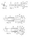
- FIG. 12 A further embodiment of the rod 47 is shown in FIG the head piece 50 shown in view, wherein in Fig.12 Rod 47 according to the section line drawn in Fig.11 C-C is shown in the profile cross section. That on the front End of the rod 47 molded head 50 with the parts 53 and 53.1 and 54 and 54.1 is analogous to that in connection above 6 to 8 described headpiece 50 formed.
- Deviating from the embodiment comprises the rod 47 according to Fig.11 and Fig.12 two in Profile cross section semicircular and with 48 and 48.1 designated sections.
- the two sections 48 and 48.1 are from the rear end towards the head 50 connected to each other for example by laser welding.
- the two are semicircular Parts as arms 48 and 48.1 through the in the axial direction oriented gap 52 separately and to achieve a resilient Preload spread relative to each other.
- Fig. 13 shows that shown on a larger scale and in section tubular probe 46 with the coaxial therein Rod 47.
- the rod 47 is with a trained as a second variant and in the open Position shown head 50 provided.
- the rod 47 is oriented through the gap 52 in two in the axial direction Arms 47.1 and 47.2 divided and on the opposite mutually arranged sides each with a in Sliding surface 51 and 51.1.
- the two arms 47.1 and 47.2 relative to each other or spread relative to the axis of symmetry S-S or bent up.
- one arm 47.1 provided with a first recess 55.1, which by a first wall 53 and formed on the inside in a circular arc bounded on the end face by a leg 54 formed thereon is.
- the other arm 47.2 is with a second recess 55.2 provided by a circular arc on the inside second wall 53.1 and by an integrally formed thereon Leg 54.1 is limited on the end face.
- the two cutouts 55.1 and 55.2 form in the closed state of the head piece 50 the recess 55.
- FIG. 14 shows the probe 46 with the rod 47 arranged coaxially therein and the head piece 50 formed thereon with the recess 55.
- the two end legs 54 and 54.1 are not designated at the ends facing one another ) positively pressed against each other.
- the clear length L of the recess 55 oriented in the axial direction of the head piece 50 is smaller than the clear width H oriented transversely thereto.
- the third variant is the rod 47, which is arranged in the tubular probe 46 and is divided with the two rod 47.1 and 47.2, which are divided by the gap 52 into two arms 47.1 and 47.2, with the head piece 50 formed thereon.
- the individual elements of the rod 47 and the head piece 50 are largely analogous to the embodiment described above in connection with FIGS. 13 and 14.
- the recesses 55.1 and 55.2 provided in the two arms 47.1 and 47.2 and the two walls 53 and 53.1 with the legs 54 and 54.1 are approximately semicircular.
- the two front legs 54 and 54.1 are pressed against one another in a form-fitting manner at the mutually facing ends (not designated).
- the clear diameter denoted by M of the recess 55 corresponds approximately to the outer diameter of 1.0 mm of the tubular probe 46.
- FIG. 17 shows a further variant of, for example, the Ophthalmic instrument 25 (Fig.3) screw-on functional unit 35 with the guide sleeve 45 in a spatial view shown.
- Deviating from that shown in Fig.4 and Fig.5 Embodiment is in this variant on the one end of the probe 46 a first in the guide sleeve 45 stored pipe section 36 and at the other end a second Pipe piece 38 attached to the probe 46.
- the one at the front end the rod 50 designed as a catch member 47 is mounted coaxially in the second pipe section 38 and penetrates the adjoining and eccentrically Hollow needle formed probe 46 and the first tube section 36.
- the first pipe section 36 with the probe 46 and the second pipe section 38 form together with that shown in Figures 4 and 5 Actuator 40 an in the axial direction relative to the head piece 50 sliding units.
- a correspondingly designed Entry opening 37 is provided through which the Light guide 22 into the interior 46.1 (FIG. 18) of the probe 46 can be introduced.
- the probe 46 is in the direction of the penetrating light guide 22 the other end with an outlet opening 49.
- Fig. 17 is shown schematically, is the exit opening 49 led out light guide 22 on the outside arranged in the pipe section 38 so that the end face 23 emerging light illuminates the recess 55 of the head piece 50.
- the light guide 22 stands with a schematically shown in Fig.17 Light source 21 in connection.
- the light source 21 is, for example, in the form of a battery in the housing 24 of the instrument 25 (Fig.3) arranged. Another variant there is the possibility that the light guide 21 directly to an ophthalmic device, not shown connected.
- Fig. 18 shows the on a larger scale and according to the in Fig. 17 drawn line D-D probe shown in section 46 and one recognizes the eccentrically arranged in the interior 46.1 Rod 47 with the two shown in profile cross section Poor 47.1 and 47.2 as well as the also eccentric Light guides 22 arranged in the interior 46.1.
- Fig. 19 shows this on a larger scale and according to the in Fig. 17 drawn line E-E shown in section and on the probe 46 arranged second pipe section 38 with the coaxial rod 47 stored therein and the outside diameter of the pipe section 38 arranged light guide 22nd
- the light guide 22 can for example with means not shown on the pipe section 38 are attached.
- the light guide 22 is preferably with one with respect to its longitudinal axis, not shown provided inclined end face 23, by means of which the individual beams 59 of the emitted light beam 58 with a limited solid angle to that provided in the head piece 50 Recess 55 is directed.
- the end face 23 of the light guide 22 formed as a lens or a lens on the front side 23 arranged.
- the outside is on the second Pipe piece 38 arranged light guide 22 with the end face 23 with respect to the end face of the pipe section, not designated 38 arranged flush.
- the respectively stored in the probe 46 designed as a hollow needle Rod 47 is preferably therein in actuator 40 arranged and fixed by means of the setscrew 43 (Fig. 4,5), that the one provided in the head piece 50 and for gripping and holding the blood vessel 12 formed recess 55, as shown schematically in Fig.2, for the ophthalmologist is clearly visible.
Landscapes
- Health & Medical Sciences (AREA)
- Surgery (AREA)
- Life Sciences & Earth Sciences (AREA)
- Medical Informatics (AREA)
- Animal Behavior & Ethology (AREA)
- Engineering & Computer Science (AREA)
- Biomedical Technology (AREA)
- Heart & Thoracic Surgery (AREA)
- Veterinary Medicine (AREA)
- Molecular Biology (AREA)
- Nuclear Medicine, Radiotherapy & Molecular Imaging (AREA)
- General Health & Medical Sciences (AREA)
- Public Health (AREA)
- Ophthalmology & Optometry (AREA)
- Surgical Instruments (AREA)
- Eye Examination Apparatus (AREA)
- Prostheses (AREA)
- Infusion, Injection, And Reservoir Apparatuses (AREA)
Applications Claiming Priority (2)
| Application Number | Priority Date | Filing Date | Title |
|---|---|---|---|
| US935869 | 1986-11-28 | ||
| US09/935,869 US6945984B2 (en) | 2001-08-23 | 2001-08-23 | Micro surgical instrument |
Publications (2)
| Publication Number | Publication Date |
|---|---|
| EP1285631A2 true EP1285631A2 (fr) | 2003-02-26 |
| EP1285631A3 EP1285631A3 (fr) | 2004-02-04 |
Family
ID=25467810
Family Applications (1)
| Application Number | Title | Priority Date | Filing Date |
|---|---|---|---|
| EP02405590A Withdrawn EP1285631A3 (fr) | 2001-08-23 | 2002-07-11 | Instrument de microchirurgie |
Country Status (4)
| Country | Link |
|---|---|
| US (1) | US6945984B2 (fr) |
| EP (1) | EP1285631A3 (fr) |
| JP (1) | JP4632621B2 (fr) |
| AU (1) | AU2002300078B2 (fr) |
Cited By (1)
| Publication number | Priority date | Publication date | Assignee | Title |
|---|---|---|---|---|
| EP3695809B1 (fr) * | 2019-02-13 | 2024-10-23 | Geuder AG | Appareil ophtalmologique portatif |
Families Citing this family (51)
| Publication number | Priority date | Publication date | Assignee | Title |
|---|---|---|---|---|
| GB0313475D0 (en) * | 2003-06-11 | 2003-07-16 | Montford University De | Contact lens manipulation and cleaning apparatus |
| NL1024492C2 (nl) * | 2003-10-09 | 2005-04-12 | Dutch Ophthalmic Res Ct B V | Chirurgisch handgereedschap, adapter, samenstel, kit en werkwijze voor het reinigen van een chirurgisch handgereedschap. |
| JP4731565B2 (ja) * | 2004-10-15 | 2011-07-27 | エム. グレイサー バート | 内境界膜掻集器具 |
| US7731728B2 (en) * | 2004-11-30 | 2010-06-08 | Glaser Bert M | Internal limiting membrane rake |
| WO2007106813A2 (fr) * | 2006-03-13 | 2007-09-20 | Minilap Technologies, Inc. | Ensemble chirurgical minimalement invasif et procedes |
| US8313507B2 (en) * | 2006-03-13 | 2012-11-20 | Mini-Lap Technologies, Inc. | Minimally invasive rake retractor and method for using same |
| US7766937B2 (en) * | 2006-03-13 | 2010-08-03 | Mini-Lap Technologies, Inc. | Minimally invasive surgical assembly and methods |
| US8133255B2 (en) * | 2006-03-13 | 2012-03-13 | Mini-Lap Technologies, Inc. | Minimally invasive surgical assembly and methods |
| US9486238B2 (en) * | 2006-03-13 | 2016-11-08 | Teleflex Medical Incorporated | Minimally invasive surgical clamps, assemblies and methods |
| US20100288285A1 (en) * | 2006-05-04 | 2010-11-18 | Marmar Joel L | Toothed vasectomy clamps and methods of using same |
| US20070282170A1 (en) * | 2006-05-30 | 2007-12-06 | Sundaram Ravikumar | Rake Retractor and Needle Assembly for Minimally Invasive Surgical Applications |
| US8414616B2 (en) | 2006-09-12 | 2013-04-09 | Pioneer Surgical Technology, Inc. | Mounting devices for fixation devices and insertion instruments used therewith |
| US20080086166A1 (en) * | 2006-10-10 | 2008-04-10 | Sundaram Ravikumar | Minimally Invasive Surgical Assembly with Balloon Instrument |
| US20080167680A1 (en) * | 2007-01-10 | 2008-07-10 | Voegele James W | Fingertip Surgical Instrument |
| US20080319463A1 (en) * | 2007-06-19 | 2008-12-25 | Dyson William Hickingbotham | Apparatus, system and method for illuminated membrane manipulator |
| JP5196645B2 (ja) * | 2008-03-21 | 2013-05-15 | Hoya株式会社 | 眼科用手術器具 |
| US8956351B2 (en) * | 2008-04-09 | 2015-02-17 | Teleflex Medical Incorporated | Minimally invasive surgical needle and cauterizing assembly and methods |
| US20100305596A1 (en) * | 2009-05-26 | 2010-12-02 | Erik William Peterson | Non-linear cut-rate multiplier for vitreous cutter |
| US9326757B2 (en) | 2009-12-31 | 2016-05-03 | Teleflex Medical Incorporated | Surgical instruments for laparoscopic aspiration and retraction |
| JP2013537068A (ja) | 2010-09-10 | 2013-09-30 | ピボット・メディカル,インコーポレーテッド | 縫合糸を組織に通すための方法および器具 |
| EP3062713B1 (fr) | 2010-09-10 | 2024-09-25 | Stryker Corporation | Appareil permettant de passer une suture au travers d'un tissu |
| US10098631B2 (en) | 2010-09-10 | 2018-10-16 | Pivot Medical, Inc. | Method and apparatus for passing suture through tissue |
| US9428254B1 (en) | 2010-09-24 | 2016-08-30 | Katalyst Surgical, Llc | Microsurgical handle and instrument |
| US10478206B2 (en) * | 2011-04-29 | 2019-11-19 | University Of Southern California | Instruments and methods for the implantation of cell-seeded substrates |
| US8821444B2 (en) | 2011-10-03 | 2014-09-02 | Katalyst Surgical, Llc | Multi-utility surgical instrument |
| US9138346B2 (en) | 2012-01-26 | 2015-09-22 | Katalyst Surgical, Llc | Surgical instrument sleeve |
| US9629645B2 (en) | 2012-10-30 | 2017-04-25 | Katalyst Surgical, Llc | Atraumatic microsurgical forceps |
| US9226762B2 (en) | 2012-11-07 | 2016-01-05 | Katalyst Surgical, Llc | Atraumatic microsurgical forceps |
| US20140135820A1 (en) * | 2012-11-13 | 2014-05-15 | Alcon Research, Ltd. | Disposable capsulorhexis forceps |
| US9204995B2 (en) | 2013-03-12 | 2015-12-08 | Katalyst Surgical, Llc | Membrane removing forceps |
| US20150088193A1 (en) * | 2013-09-24 | 2015-03-26 | Katalyst Surgical, Llc | Membrane removing forceps |
| US20150148838A1 (en) * | 2013-11-26 | 2015-05-28 | Novartis Ag | Systems and Methods for a Surgical Tissue Manipulator |
| CN105792783B (zh) * | 2013-11-28 | 2019-07-26 | 爱尔康制药有限公司 | 眼外科手术系统、方法和装置 |
| US10010447B2 (en) | 2013-12-18 | 2018-07-03 | Novartis Ag | Systems and methods for subretinal delivery of therapeutic agents |
| US9730834B2 (en) | 2013-12-20 | 2017-08-15 | Novartis Ag | Variable stiffness cannula and methods for a surgical system |
| US10022267B2 (en) | 2014-04-21 | 2018-07-17 | Katalyst Surgical, Llc | Method of manufacturing a microsurgical instrument tip |
| US9775943B2 (en) | 2014-10-10 | 2017-10-03 | Katalyst Surgical, Llc | Cannula ingress system |
| US20170296382A1 (en) * | 2014-10-24 | 2017-10-19 | Kaneka Corporation | Micro forceps |
| US10744032B2 (en) * | 2015-11-12 | 2020-08-18 | Mor Research Applications Ltd. | Instrument for extracting nucleus of eye lens during cataract surgery |
| WO2017218161A1 (fr) | 2016-06-16 | 2017-12-21 | Katalyst Surgical, Llc | Manche d'instrument réutilisable à pointe à usage unique |
| US10695043B2 (en) | 2017-02-21 | 2020-06-30 | Katalyst Surgical, Llc | Surgical instrument subcomponent integration by additive manufacturing |
| US10660793B2 (en) | 2017-08-09 | 2020-05-26 | Vortex Surgical | Medical device and methods of manufacturing thereof |
| JP6959854B2 (ja) * | 2017-12-25 | 2021-11-05 | 謙一 松村 | 医療用鑷子 |
| WO2019155299A1 (fr) | 2018-02-09 | 2019-08-15 | Novartis Ag | Systèmes de fixation d'outil chirurgical et procédé d'utilisation |
| US10849640B2 (en) | 2018-05-23 | 2020-12-01 | Katalyst Surgical, Llc | Membrane aggregating forceps |
| US20200345382A1 (en) * | 2019-05-01 | 2020-11-05 | Bibianna Cha | Inline cutter for cutting and retrieving implanted microsurgical devices |
| JP7695244B2 (ja) | 2019-12-11 | 2025-06-18 | アルコン インコーポレイティド | 手術器械用の調整可能な補剛材 |
| US11540941B2 (en) | 2019-12-11 | 2023-01-03 | Alcon Inc. | Adjustable support sleeve for surgical instruments |
| US12186236B2 (en) | 2021-08-26 | 2025-01-07 | Alcon Inc. | Adjustable stiffener for surgical instruments |
| WO2023073461A1 (fr) | 2021-10-28 | 2023-05-04 | Alcon Inc. | Outil extensible à l'intérieur d'un manchon de renforcement |
| EP4633557A1 (fr) | 2022-12-14 | 2025-10-22 | Alcon Inc. | Structure de préhension pour retrait de membrane |
Family Cites Families (17)
| Publication number | Priority date | Publication date | Assignee | Title |
|---|---|---|---|---|
| US2549731A (en) * | 1944-12-18 | 1951-04-17 | Vincent E Wattley | Flexible test prod |
| DE3012447C2 (de) * | 1980-03-31 | 1982-04-01 | Harald 7200 Tuttlingen Maslanka | Chirurgisches Greiferinstrument |
| FR2505170B1 (fr) * | 1981-05-06 | 1985-08-02 | Metallisations Traitements Opt | Pince a biopsie |
| US4655219A (en) * | 1983-07-22 | 1987-04-07 | American Hospital Supply Corporation | Multicomponent flexible grasping device |
| US5486185A (en) * | 1989-01-30 | 1996-01-23 | Dexide, Inc. | Surgical apparatus |
| US5797958A (en) * | 1989-12-05 | 1998-08-25 | Yoon; Inbae | Endoscopic grasping instrument with scissors |
| US5222973A (en) * | 1992-03-09 | 1993-06-29 | Sharpe Endosurgical Corporation | Endoscopic grasping tool surgical instrument |
| US5514148A (en) * | 1994-11-04 | 1996-05-07 | Smith, Iii; Ray C. | Surgical clamp and method of use |
| DE19533856A1 (de) * | 1995-09-13 | 1997-03-20 | Balazs Mattias | Medizinisches Instrument |
| WO1997015234A1 (fr) * | 1995-10-23 | 1997-05-01 | Johns Hopkins University | Instrument chirurgical |
| US5916149A (en) * | 1995-10-25 | 1999-06-29 | Ryan, Jr.; Edwin H. | Shielded illumination device for ophthalmic surgery and the like |
| US5746770A (en) * | 1995-11-22 | 1998-05-05 | Zeitels; Jerrold Roy | Endoscopic retriever |
| US5735849A (en) * | 1996-11-07 | 1998-04-07 | Everest Medical Corporation | Endoscopic forceps with thumb-slide lock release mechanism |
| US5893878A (en) * | 1997-04-24 | 1999-04-13 | Pierce; Javin | Micro traumatic tissue manipulator apparatus |
| WO2001037767A1 (fr) | 1999-11-24 | 2001-05-31 | Grieshaber & Co. Ag | Dispositif pour ameliorer l'evacuation de l'humeur aqueuse de l'oeil d'un etre vivant |
| US6855156B2 (en) * | 2000-10-19 | 2005-02-15 | Grieshaber & Co. Ag Schaffhausen | Ophthalmic microsurgical instrument |
| US6908476B2 (en) * | 2001-12-21 | 2005-06-21 | Alcon Grieshaber Ag | Micro surgical cutting instrument configured as scissors |
-
2001
- 2001-08-23 US US09/935,869 patent/US6945984B2/en not_active Expired - Lifetime
-
2002
- 2002-07-11 EP EP02405590A patent/EP1285631A3/fr not_active Withdrawn
- 2002-07-11 AU AU2002300078A patent/AU2002300078B2/en not_active Ceased
- 2002-08-06 JP JP2002228608A patent/JP4632621B2/ja not_active Expired - Lifetime
Cited By (1)
| Publication number | Priority date | Publication date | Assignee | Title |
|---|---|---|---|---|
| EP3695809B1 (fr) * | 2019-02-13 | 2024-10-23 | Geuder AG | Appareil ophtalmologique portatif |
Also Published As
| Publication number | Publication date |
|---|---|
| JP2003102768A (ja) | 2003-04-08 |
| US6945984B2 (en) | 2005-09-20 |
| EP1285631A3 (fr) | 2004-02-04 |
| JP4632621B2 (ja) | 2011-02-16 |
| AU2002300078B2 (en) | 2006-10-19 |
| US20030040773A1 (en) | 2003-02-27 |
Similar Documents
| Publication | Publication Date | Title |
|---|---|---|
| EP1285631A2 (fr) | Instrument de microchirurgie | |
| EP1325710A2 (fr) | Ciseaux de microchirurgie | |
| DE102004027881B4 (de) | Knochenschraube und Osteosynthesevorrichtung | |
| DE69632872T2 (de) | Spannbackenanordnung für endoskopische instrumente | |
| DE69006995T2 (de) | Gelenkbolzen für orthodontische vorrichtungen und vorrichtung mit einem solchen gelenkbolzen. | |
| DE19836950B4 (de) | Chirurgisches Instrument in Form eines Nahtklammergerätes | |
| EP0892620B1 (fr) | Coupe-fils chirurgical | |
| EP0941713B1 (fr) | Dispositif pour introduire une endoprothèse dans le tube d' un cathéter | |
| DE69635087T2 (de) | Super-elastische flexibele spannbackenanordnung | |
| DE2816961C2 (de) | Vorrichtung zum Anlegen einer Klammer an einen Eileiter | |
| DE69611848T2 (de) | Medizinische Vorrichtung | |
| DE69531878T2 (de) | Vorrichtung zum kontrollierten Einsetzen einer Intraokularlinse | |
| DE4032601C2 (fr) | ||
| EP0594946B1 (fr) | Instrument endoscopique de coupe et/ou pince endoscopique | |
| EP2335609B1 (fr) | Instrument chirurgical | |
| WO2001037767A1 (fr) | Dispositif pour ameliorer l'evacuation de l'humeur aqueuse de l'oeil d'un etre vivant | |
| EP0876807A1 (fr) | Adaptateur pour connecter une emplanture de moignon avec la tige d'une prothèse | |
| EP0763347A1 (fr) | Pince chirurgical hémostatique | |
| WO2000067642A2 (fr) | Retracteur utilise en chirurgie endoscopique, instrument medical pour l'introduction d'un retracteur, et procede d'utilisation d'un retracteur en chirurgie endoscopique | |
| EP0780091A1 (fr) | Aiguille médicale de pénétration des tissus corporels | |
| EP1163886A2 (fr) | Résectoscope HF | |
| DE3209444A1 (de) | Endoskopisches zusatzgeraet fuer einen chirurgischen laser | |
| DE69428205T2 (de) | Instrument zum lösen und durchschneiden der intima eines blutgefässes | |
| DE69936509T2 (de) | Stossgedämpftes biopsie gerät | |
| EP2725988B1 (fr) | Système de trocart |
Legal Events
| Date | Code | Title | Description |
|---|---|---|---|
| PUAI | Public reference made under article 153(3) epc to a published international application that has entered the european phase |
Free format text: ORIGINAL CODE: 0009012 |
|
| AK | Designated contracting states |
Kind code of ref document: A2 Designated state(s): AT BE BG CH CY CZ DE DK EE ES FI FR GB GR IE IT LI LU MC NL PT SE SK TR Designated state(s): AT BE BG CH CY CZ DE DK EE ES FI FR GB GR IE IT LI LU MC NL PT SE SK TR |
|
| AX | Request for extension of the european patent |
Extension state: AL LT LV MK RO SI |
|
| PUAL | Search report despatched |
Free format text: ORIGINAL CODE: 0009013 |
|
| AK | Designated contracting states |
Kind code of ref document: A3 Designated state(s): AT BE BG CH CY CZ DE DK EE ES FI FR GB GR IE IT LI LU MC NL PT SE SK TR |
|
| AX | Request for extension of the european patent |
Extension state: AL LT LV MK RO SI |
|
| 17P | Request for examination filed |
Effective date: 20040329 |
|
| AKX | Designation fees paid |
Designated state(s): AT BE BG CH CY CZ DE DK EE ES FI FR GB GR IE IT LI LU MC NL PT SE SK TR |
|
| AXX | Extension fees paid |
Extension state: SI Payment date: 20020718 Extension state: RO Payment date: 20020718 Extension state: LV Payment date: 20020718 Extension state: LT Payment date: 20020718 Extension state: AL Payment date: 20020718 |
|
| 17Q | First examination report despatched |
Effective date: 20050411 |
|
| STAA | Information on the status of an ep patent application or granted ep patent |
Free format text: STATUS: THE APPLICATION IS DEEMED TO BE WITHDRAWN |
|
| 18D | Application deemed to be withdrawn |
Effective date: 20060707 |