EP1285742A2 - Optische Kunststofffolie, Verfahren zu deren Herstellung und Polarisator - Google Patents
Optische Kunststofffolie, Verfahren zu deren Herstellung und Polarisator Download PDFInfo
- Publication number
- EP1285742A2 EP1285742A2 EP02017529A EP02017529A EP1285742A2 EP 1285742 A2 EP1285742 A2 EP 1285742A2 EP 02017529 A EP02017529 A EP 02017529A EP 02017529 A EP02017529 A EP 02017529A EP 1285742 A2 EP1285742 A2 EP 1285742A2
- Authority
- EP
- European Patent Office
- Prior art keywords
- film
- optical film
- chill roll
- temperature
- thickness
- Prior art date
- Legal status (The legal status is an assumption and is not a legal conclusion. Google has not performed a legal analysis and makes no representation as to the accuracy of the status listed.)
- Granted
Links
Images


Classifications
-
- C—CHEMISTRY; METALLURGY
- C08—ORGANIC MACROMOLECULAR COMPOUNDS; THEIR PREPARATION OR CHEMICAL WORKING-UP; COMPOSITIONS BASED THEREON
- C08J—WORKING-UP; GENERAL PROCESSES OF COMPOUNDING; AFTER-TREATMENT NOT COVERED BY SUBCLASSES C08B, C08C, C08F, C08G or C08H
- C08J5/00—Manufacture of articles or shaped materials containing macromolecular substances
- C08J5/18—Manufacture of films or sheets
-
- B—PERFORMING OPERATIONS; TRANSPORTING
- B29—WORKING OF PLASTICS; WORKING OF SUBSTANCES IN A PLASTIC STATE IN GENERAL
- B29C—SHAPING OR JOINING OF PLASTICS; SHAPING OF MATERIAL IN A PLASTIC STATE, NOT OTHERWISE PROVIDED FOR; AFTER-TREATMENT OF THE SHAPED PRODUCTS, e.g. REPAIRING
- B29C48/00—Extrusion moulding, i.e. expressing the moulding material through a die or nozzle which imparts the desired form; Apparatus therefor
- B29C48/25—Component parts, details or accessories; Auxiliary operations
- B29C48/88—Thermal treatment of the stream of extruded material, e.g. cooling
- B29C48/911—Cooling
- B29C48/9135—Cooling of flat articles, e.g. using specially adapted supporting means
- B29C48/915—Cooling of flat articles, e.g. using specially adapted supporting means with means for improving the adhesion to the supporting means
- B29C48/916—Cooling of flat articles, e.g. using specially adapted supporting means with means for improving the adhesion to the supporting means using vacuum
-
- B—PERFORMING OPERATIONS; TRANSPORTING
- B29—WORKING OF PLASTICS; WORKING OF SUBSTANCES IN A PLASTIC STATE IN GENERAL
- B29C—SHAPING OR JOINING OF PLASTICS; SHAPING OF MATERIAL IN A PLASTIC STATE, NOT OTHERWISE PROVIDED FOR; AFTER-TREATMENT OF THE SHAPED PRODUCTS, e.g. REPAIRING
- B29C48/00—Extrusion moulding, i.e. expressing the moulding material through a die or nozzle which imparts the desired form; Apparatus therefor
- B29C48/03—Extrusion moulding, i.e. expressing the moulding material through a die or nozzle which imparts the desired form; Apparatus therefor characterised by the shape of the extruded material at extrusion
- B29C48/07—Flat, e.g. panels
- B29C48/08—Flat, e.g. panels flexible, e.g. films
-
- B—PERFORMING OPERATIONS; TRANSPORTING
- B29—WORKING OF PLASTICS; WORKING OF SUBSTANCES IN A PLASTIC STATE IN GENERAL
- B29C—SHAPING OR JOINING OF PLASTICS; SHAPING OF MATERIAL IN A PLASTIC STATE, NOT OTHERWISE PROVIDED FOR; AFTER-TREATMENT OF THE SHAPED PRODUCTS, e.g. REPAIRING
- B29C48/00—Extrusion moulding, i.e. expressing the moulding material through a die or nozzle which imparts the desired form; Apparatus therefor
- B29C48/25—Component parts, details or accessories; Auxiliary operations
- B29C48/88—Thermal treatment of the stream of extruded material, e.g. cooling
- B29C48/911—Cooling
- B29C48/9135—Cooling of flat articles, e.g. using specially adapted supporting means
- B29C48/914—Cooling drums
-
- B—PERFORMING OPERATIONS; TRANSPORTING
- B29—WORKING OF PLASTICS; WORKING OF SUBSTANCES IN A PLASTIC STATE IN GENERAL
- B29K—INDEXING SCHEME ASSOCIATED WITH SUBCLASSES B29B, B29C OR B29D, RELATING TO MOULDING MATERIALS OR TO MATERIALS FOR MOULDS, REINFORCEMENTS, FILLERS OR PREFORMED PARTS, e.g. INSERTS
- B29K2995/00—Properties of moulding materials, reinforcements, fillers, preformed parts or moulds
- B29K2995/0018—Properties of moulding materials, reinforcements, fillers, preformed parts or moulds having particular optical properties, e.g. fluorescent or phosphorescent
Definitions
- the present invention relates to an optical film applicable for optical, display and other uses, a method for manufacture thereof and a sheet polarizer, and more particularly to an optical film which is obtainable by melt extrusion and exhibits a low optical strain, a method for manufacture thereof and a sheet polarizer using the optical film.
- a stress-induced strain is produced therein based on deformation thereof during film formation and remains as an optical strain.
- Japanese Patent Laying-Open No. Hei 4-275129 discloses a method for manufacturing an optical film by extruding a polycarbonate resin at a resin temperature of 300 - 330 °C, i.e., at a temperature from (a glass transition temperature (Tg) + 150 °C) to (Tg + 180 °C), an air gap of 80 - 100 mm, and a chill roll temperature of 100 - 140 °C.
- Tg glass transition temperature
- Japanese Patent Laying-Open No. 2000-280268 discloses a method for manufacturing an optical film which has a residual phase difference of not exceeding 10 nm by extruding a resin having a glass transition temperature Tg while temperatures of extrusion belts and rolls are maintained within the range from Tg to (Tg + 50 °C). This method results in obtaining a 0.1 - 2 mm thick film.
- a phenomenon that a phase difference (optical strain) remains in a film occurs due to the monoaxial orientation of molecules in a film.
- the phase difference is produced and left in the film as the residual phase difference when a film-forming resin is deformed at Tg or higher temperatures and is proportional to a magnitude of a stress engendered during deformantion.
- the stress produced during deformation depends on the temperature and magnitude of deformation of the resin. Accordingly, if the magnitude of deformation remains constant, the stress varies with the resin temperature.
- a resin extruded from a die is generally drawn down to a target film thickness within an air gap, during which time a resin temperature drops.
- the lower the resin temperature the higher the stress produced during deformation. The higher stress leads to the larger phase difference which is left behind.
- Optical films for use in optical and display areas suffer from several problems including the residual phase difference that indicates a magnitude of an optical strain, and the dispersion of an optical axis in which direction the optical strain is produced.
- noncrystalline thermoplastic resins are primarily employed.
- the use of a saturated norbornene resin, among them, is particularly advantageous, because it has superior heat resistance, high transparency, a low intrinsic birefringence and a low photoelastic coefficient.
- a sheet polarizer having protective films provided on opposite sides of a polarizer has been used for a liquid crystal display (LCD).
- a typical polarizer comprises an iodine- or dichloric dye-adsorbed, oriented polyvinyl alcohol film.
- useful protective films include an untreated triacetylcellulose (TAC) film, an alkali-treated TAC film and the like.
- the aforementioned protective film and other optical films have been manufactured by a casting process which is effective in providing films with superior optical and other physical properties.
- a sheet polarizer using a TAC film obtained via such a casting process as a polarizer protecting film because of a large photoelastic coefficient of the TAC film, has encountered the following problems in polarization characteristics: birefringence and optical axis deviation increase and light leakage occurs in the crossed nicol arrangement.
- Japanese Patent Laying-Open No. Hei 6-51120 proposes a sheet polarizer which has transparent protective layers having retardation values of up to 3 nm and provided on opposite sides of a film polarizer.
- an object of the present invention to provide an optical film, made of a noncrystalline thermoplastic resin, which exhibits not only a small residual phase difference but also a minimized variation of an optical axis, and also to provide a method for manufacture thereof.
- a first invention of the present application is an optical film obtained via melt extrusion of a noncrystalline thermoplastic resin, which is characterized as having a thickness of below 100 ⁇ m, a residual phase difference of up to 10 nm, preferably up to 3 nm, and an optical axis deviation within the range of ⁇ 10°.
- a second invention of the present application is an optical film obtained via melt extrusion of a noncrystalline thermoplastic resin, which is characterized as having a thickness of below 100 ⁇ m and a residual phase difference of up to 1 nm.
- a variation of an optical axis deviation becomes insignficant, since the residual phase difference does not exceed 1 nm.
- a retardation Rs (40) and a retardation Rf (40) are rendered to fall within R(0) + 6 nm.
- the Rs (40) and Rf (40) respectively indicate the retardation measured along a direction slanted at an angle of 40° toward the fast axis and slow axis from a normal direction of the optical film.
- R(0) indicates a retardation in a normal direction.
- thermoplastic resin used as the noncrystalline thermoplastic resin is a saturated norbornene resin which is not only superior in heat resistance and transparency but low in intrinsic birefringence and photoelastic coefficient.
- saturated norbornene resin having such advantages results in the provision of an optical film which exhibits a low residual phase difference and a small variation of an optical axis.
- a method for manufacture of an optical film according to the first inveniotn comprises a step of obtaining a film of a noncrystalline thermoplastic resin by extruding the noncrystalline thermoplastic resin having a glass transition temperature Tg from an extrusion die into a film and a step of making the film which is subsequently into contact with a chill roll, and the temperature of the resin just before being brought into contact with the chill roll is controlled at a temperature (Tg + 50 °c) or higher.
- Tg + 50 °c a temperature
- the temperature of the resin just before being brought into contact with the chill roll is controlled at a temperature (Tg + 80 °C) or higher. This results in obtaining an optical film with a residual phase difference of 3 nm or lower.
- a method for manufacture of an optical film according to the first invention comprises a step of obtaining a film of a noncrystalline thermoplastic resin by extruding the non crystalline thermoplastic resin having a glass transition temperature Tg from an extrusion die into a film and a step of making the film which is subsequently into contact with a chill roll.
- B/A is maintained at a value of up to 10 if A is not below 70 ⁇ m but below 100 ⁇ m, at a value of up to 15 if A is not below 50 ⁇ m but below 70 ⁇ m and at a value of up to 20 if A is below 50 ⁇ m, wherein A is a thickness of the film right after being brought into contact with the chill roll and B is a lip clearance of the die. Also, the temperature of the resin just before being brought into contact with the chill roll is controlled at a temperature at (Tg + 30 °C) or higher.
- a method for manufacture of an optical film according to the second invention comprises a step of obtaining a film of a noncrystalline thermoplastic resin by extruding the non crystalline thermoplastic resin having a glass transition temperature Tg from an extrusion die into a film and a step of making the film which is subsequently into contact with a chill roll.
- a temperature of the resin immediately after it passes a die exit is controlled at a temperature at (Tg + 130 °c) or higher and a temperature of the film from the die exit to the contact point with the chill roll is maintained not to fall below (Tg + 100 °C).
- Tg + 130 °c a temperature of the film from the die exit to the contact point with the chill roll
- a noncrystalline thermoplastic resin is extruded from an extrusion die into a film which is subsequently brought into contact with a chill roll. On this occasion, the film is kept warm within an air gap from the die exit to the contact point of the film and the chill roll.
- a third invention of this application is an optical film obtained via melt extrusion of a noncrystalline thermoplastic resin.
- the film is characterized as having a thickness of below 100 ⁇ m, a retardation value R(0) of up to 3 nm, a lengthwise optical axis deviation within the range of ⁇ 10°, and a thickness precision as specified by the following (a) or (b), wherein the R(0) indicates the retardation in a normal direction.
- a norbornene resin is used as the noncrystalline thermoplastic resin.
- optical films in accordance with the first through third inventions can be suitably used as protective films for protecting polarizers.
- a sheet polarizer including a polarizer and the optical film, in accordance with any one of the first through third inventions, overlying at least one surface of the polarizer.
- the first invention of the present invention is an optical film obtained via extrusion of a noncrystalline thermoplastic resin and having a thickness of below 100 ⁇ m, a residual phase difference of up to 10 nm, preferably up to 3 nm, and an optical axis deviation within the range of ⁇ 10°.
- the second invention of the present invention is an optical film obtained via extrusion of a noncrystalline thermoplastic resin and having a thickness of below 100 ⁇ m and a residual phase difference of up to 1 nm.
- Optical films having residual phase differences up to 10 nm, preferably up to 3 nm, more pref phase difference sheet erably up to 1 nm, are suitably applicable for uses such as optical discs and liquid crystal displays.
- raw films for a retardation film and protective films for a sheet polarizer, particularly for use in the manufacture of liquid crystal displays are required having low phase differences.
- the optical film in accordance with the present invention because of its very low phase difference, is particularly effective for such uses.
- an optical axis deviation of the optical film is within the range of ⁇ 10°
- the application of the optical film in accordance with the present invention for optical uses increases a proportion of non-defectives.
- its use as a protective film for a sheet polarizer suppresses nonuniformity of display.
- a thickness of the optical film is below 100 ⁇ m, its use permits reduction in sizes of optical discs, liquid crystal displays and the like.
- an optical axis deviation which becomes a problem when conventional films with phase differences of exceeding 1 nm are applied for optical uses is made negligible.
- a retardation Rs(40) and a retardation Rf(40), as measured along respective lines slanted at an angle of 40° toward the fast axis and slow axis from the normal line of the optical film, are maintained not to exceed R(0) + 6 nm.
- the retardation refers to a product of a difference between refractive indices in birefringence and a thickness, and is given by a value measured using a light at a wavelength of 590 nm according to a rotating polarizer method.
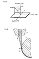
- Figure 5 is a perspective view, showing a retardation R(0) as measured along a line normal to the optical film and a retardation Rs(40) as measured along a line slanted at an angle of 40 degrees toward the fast axis from the normal line of the optical film.
- the retardation R(0) specified in the present invention is a retardation value when measured along a line normal to the optical film.
- the retardation Rs(40) specified in the present invention is a retardation value when measured along a line slanted at an angle of 40 degrees toward the fast axis from the normal line of the optical film.
- the retardation Rf(40) specified in the present invention is a retardation value when measured along a line slanted at an angle of 40 degrees toward the slow axis from the normal line of the optical film.
- the slow axis generally coincides with a direction corresponding to the highest refractive index in a film plane.
- the fast axis coincides with a direction perpendicular to the slow axis.
- the optical film of the first invention needs to have a retardation R(0) of up to 10 nm, preferably up to 5 nm, more preferably up to 3 nm and most preferably up to 1 nm. If the retardation R(0) exceeds 10 nm, a contrast of an LCD when viewed from its front is lowered.
- the optical films of the first and second inventions preferably have a retardation Rs(40) and a retardation Rf(40) both within R(0) + 6 nm, more preferably within R(0) + 5 nm, further preferably within R(0) + 2 nm. If either or both of Rs(40) and Rf(40) exceed R(0) + 6 nm, a contrast of an LCD when viewed at an angle decreases.
- the optical films of the first and second inventions are suitably used as protective films for protection of a polarizer constituting a sheet polarizer.
- the polarizer is easy to break when a tearing force is applied thereto and susceptible to decoloration, deformation or the like under high-humidity conditions.
- a protective film is often placed thereon.
- the use of a TAC film as the protective film, as described earlier, causes problems including light leakage or other inconveniences in polarization characteristics.
- the use of the optical film having retardations Rs(40) and Rf(40) within the above-specified respective ranges in accordance with the first or second invention effectively prevents the occurrence of light leakage or other inconveniences in polarization characteristics.
- a sheet polarizer fabricated using this optical film when placed in the crossed nicol arrangement, shows lower leakage of light when observed either from a front or at an angle and exhibits excellent polarization characteristics. Because this optical film has a thickness of below 100 ⁇ m and an optical axis deviation within 10°, the use of the optical film permits reduction in size and thickness of a sheet polarizer fabricated using this optical film and an LCD using this sheet polarizer. Also, nonuniform display is maintained at a low degree of occurrrence in such an LCD. That is, the optical film of the present invention has excellent properties as described above and is suitable for use in the fabrication of a sheet polarizer.
- Manufacture of the optical film in accordance with the first invention is not particularly specified and can be accomplished by various methods including the following first through third methods.
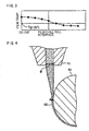
- a temperature of the film immediately before being brought into contact with the chill roll is controlled at a temperature of Tg + 50 °C or higher, as shown in Figure 1. Accordingly, a small stress remains in a resin if the film undergoes deformation in such a condition. As a result, a phase difference remaining in the film can be reduced to 10 nm or below.
- a temperature of the film immediately before being brought into contact with the chill roll is controlled at a temperature of Tg + 80 °C or higher. Since the temperature of the film immediately before being brought into contact with the chill roll is controlled at a temperature of Tg + 80 °C or higher, as shown in Figure 2, a stress in the resin becomes very small even if the film while in such a condition undergoes deformation. Hence, the phase difference remaining in the film can be reduced to 10 nm or below, or even to 3 nm or below.
- a temperature of the film immediately before being brought into contact with the chill roll is controlled not to fall below Tg + 50 °C or Tg + 80 °C.
- Control of a die temperature may be considered as one applicable method. In this case, if the die temperature is raised excessively, some types of resins may be caused to deteriorate by heat. However, the selection of a suitable temperature condition that does not cause heat deterioration assures provision of an optical film which satisfies the above-specified phase difference. Shortening of an air gap is another applicable method by which a temperature of the film immediately before being brought into contact with the chill roll is controlled not to fall below Tg + 50 °C or Tg + 80 °C.
- the distance of the air gap may be determined with due regard to a die line and a thickness precision of the film.
- the distance of the air gap is not particularly specified but preferably in the approximate range of 30 - 150 mm in view of a film quality and heat insulation effectiveness.
- the technique by which the widthwise temperature variation of the film just before being brought into contact with the chill roll is maintained within 10 °C is not particularly specified.
- Examples of such techniques include increasing a precision of a die temperature control, use of a heater having an output varied in its width direction and located within the air gap so that a resin temperature is kept uniform across the width of the film, and passing the film through an insulating box for protection thereof from outer turbulence.
- a noncrystalline thermoplastic resin having a glass transition temperature Tg is extruded from an extrusion die into a film which is then brought into contact with a chill roll. If a thickness of the film right after being brought into contact with the chill roll is given by A and a lip clearance of the die is given by B, B/A is maintained at a value of up to 10 if A is not below 70 ⁇ m but below 100 ⁇ m, at a value of up to 15 if A is not below 50 ⁇ m but below 70 ⁇ m and at a value of up to 20 if A is below 50 ⁇ m. Also, the temperature of the resin just before being brought into contact with the chill roll is controlled not to fall below Tg + 30 °C.
- a noncrystalline thermoplastic resin while in a molten state is extruded from a die 11 having a lip clearance B and then transferred to a chill roll 13, as shown in Figure 4.
- a temperature of a film 12 immediately before being brought into close contact with a peripheral surface of the chill roll 13 is controlled at a temperature of Tg + 30 °C or higher, wherein Tg is a glass transition temperature of the noncrystalline thermoplastic resin.
- B/A is set at the above-specified value. The value of B/A can be controlled to fall within the specified range by using a method wherein the lip clearance B of the die 11 is adjusted with respect to the thickness of the optical film.
- the narrower lip clearance B is enabled by increasing a resin temperature so that a melt viscosity is lowered or decreasing an extrusion rate.
- ratio B/A i.e., a draw ratio
- a resin temperature may be lowered within the air gap. Then, a higher phase difference will remain in an optical film obtained via drawing of the resin.
- a manufacturing method is next described which results in obtaining the optical film having a residual phase difference of up to 1 nm in accordance with the second invention.
- the following method merely illustrates an applicable manufacturing method which results in obtaining the optical film having a residual phase difference of up to 1 nm in accordance with the second invention and is not intended to be limiting.
- a method for manufacture of an optical film in accordance with the second invention involves extruding a noncrystalline thermoplastic resin having a glass transition temperature Tg from an extrusion die into a film which is subsequently brought into-contact with a chill roll.
- a temperature of the resin immediately after it passes a die exit is controlled not to fall below (Tg + 130 °c) and a temperature of the film before the film from the die exit is brought into contact with the chill roll is maintained not to fall below (Tg + 100 °C).
- Tg + 130 °c a temperature of the film before the film from the die exit is brought into contact with the chill roll
- Tg + 100 °C a temperature variation of the film along its width direction, both immediately after it passes the die exit and immediately before it is brought into contact with the chill roll, is maintained within 10 °C.
- a temperature of the resin immediately after it passes a die exit is controlled not to fall below (Tg + 130 °C), for example, by controlling a temperature of the die.
- Tg + 130 °C a temperature of the die.
- the die temperature is raised to an excessive level, some types of resins are more likely to undergo deterioration by heat.
- the selection of a temperature level that does not cause heat deterioration assures provision of an optical film having a reduced phase difference. It is also effective to reduce heat dissipation of the resin to the lowest level, if possible, by shortening the air gap.
- the temperature of the film immediately before it is brought into contact with the chill roll can be maintained not to fall below (Tg + 100 °C), for example, by raising a die temperature in advance to compensate for an estimated temperature drop of the resin due to its heat dissipation within the air gap, or by shortening the air gap, as stated earlier.
- Other applicable techniques include prevention of temperature drop of the resin as by insulating or positively heating the resin while passing through the air gap. Although not limiting, such techniques can be carried out by enclosing the air gap with an insulating box, or placing a heater near the film while passing through the air gap.
- the distance of the air gap is not particularly specified but is preferably in the approximate range of 30 - 150 mm in view of a film quality and heat insulation effectiveness.
- the technique used to maintain the widthwise temperature variation of the film within 10 °C is not particularly specified.
- useful techniques include increasing a precision of a die temperature, use of a heater having an output varied in its width direction and located within the air gap so that a resin temperature is kept uniform across the width of the film, and passing the film through an insulating box for protection thereof from outer turbulence.
- an optical film can be obtained having a residual phase difference within 1 nm, a deviation of an optical axis that becomes a problem when conventional films with phase differences of exceeding 1 nm are applied for optical uses is made negligible.
- This permits marked simplification of a troublesome control operation in conventional manufacturing processes that is directed to achieve alignment of an optical axis.
- those defects that have conventionally existed and are attributed to an optical axis deviation are completely removed, a yield rate of a product is markedly improved and, as a result, a product inspection step can be eliminated.
- a noteworthy optical film can be provided.
- a noncrystalline thermoplastic resin is extruded from an extrusion die into a film which is subsequently brought into contact with a chill roll. On this occasion, the film is kept warm within an air gap from the die exit to the film/chill roll interface.
- the temperature control of the film just before being brought into the chill roll is achieved by keeping the film warm within the air gap.
- a temperature change of the film in this case is made smaller than in the case shown in Figure 1.
- the temperature control is achieved with the increased precision by this technique than by the technique in which the die temperature is varied. Accordingly, a temperature variation across the width of the film is made smaller.
- This technique is effective particularly when a resin which must be placed under high-precision temperature control, such as a norbornene resin, is used.
- Another advantage of this technique is that it can prevent deterioration of the resin that results when the die temperature is raised excessively.
- the film while passing through the air gap is kept warm so that it is preferably maintained at a temperature of Tg + 30 °C or higher, more preferably Tg + 50 °C or higher, particularly preferably Tg + 80 °C or higher, further preferably Tg + 100 °C or higher.
- Tg + 30 °C or higher more preferably Tg + 50 °C or higher, particularly preferably Tg + 80 °C or higher, further preferably Tg + 100 °C or higher.
- the resulting optical film exhibits a residual phase difference of up to 3 nm or up to 1 nm.
- the film can be kept warm within the air gap by placing a suitable heat source or heat insulating device, such as a heater or insulating box, along the air gap, while leaving the die or air gap condition unaltered.
- a suitable heat source or heat insulating device such as a heater or insulating box
- the length of the air gap along which the film is kept warm may be suitably chosen from a general range of 30 - 150 mm.
- the film is preferably brought into close contact with the chill roll either by pressing the film against the chill roll or by suction from a side of the chill roll.
- a molten resin from a die is forcibly brought into close contact with the chill roll.
- any device which applies a force uniformly across the width of the film can be utilized to stabilize contact between the film and the chill roll.
- Example of such devices include those generally used in the art, such as an air chamber, a vacuum nozzle, a static pinning and a touch roll.
- the chill roll temperature is varied depending upon the type of the resin used, but is generally preferably maintained at a temperature within the range from a Tg of a resin to Tg - 100 °C.
- the third invention is an optical film obtained via melt extrusion of a noncrystalline thermoplastic resin and having a thickness of below 100 ⁇ m.
- the optical film is characterized as having a normal retardation value R(0) of up to 3 nm, a lengthwise optical axis deviation within the range of ⁇ 10°, and the thickness precision as previously specified by (a) or (b).
- the thickness precision across a full width of the film refers to a value obtained by subtracting a minimum thickness value from a maximum thickness value along the width of the film.
- the optical film in accordance with the third invention satisfies the thickness precision as indicated by (a) or (b). In this case, it may further have additional regions, at its widthwise end regions, which fail to satisfy the foregoing thickness precision. That is, a film when melt extruded from a die may have opposite end regions, each extending 10 % of a film width from the respective widthwise end, which fail to satisfy (a) or (b) the thickness, so long as its region extending between both end regions satisfies the thickness precision indicated by (a) or (b). Such a film may be made useful as an optical film by removal of the end regions that fail to satisfy the thickness precision.
- the thickness precision per 2 cm width refers to a value obtained by substracting a minimum thickness value from a maximum thickness value for an arbitrary 2 cm wide portion of the film.
- the difference in elevation between a peak and a neighboring valley on the thickness curve along the width direction refers to the elevation difference indicated on the thickness curve of Figure 8 as measured along the width direction.
- the peak and the neighboring valley refer to those which are spaced widthwise from each other by a distance of at least 20 mm but exclude those with a small elevation difference of below 1 ⁇ m.
- the optical film in accordance with the third invention is obtained via melt extrusion of a noncrystalline thermoplastic resin.
- the technique used is not particularly specified. However, the following manufacturing technique may be utilized to obtain the optical film, for example.
- the optical film in accordance with the third invention can be obtained by supplying a noncrystalline thermoplastic resin into a melt extruder and then extruding it from an extruder die.
- a clearance at the die exit is preferably uniformed in its width direction to establish a consistancy of thickness precision.
- the optical film having the thickness precision specified in the third invention can be obtained if a clearance variation at the die exit is held within 1/10 of a variation in thickness precision of the film.
- the distance of the air gap is varied depending upon the viscosity of the resin used and the final thickness of the film, but is generally in the range of 30 - 100 mm.
- B/A may preferably be maintained at a value of up to 20, while not limiting.
- a technique used to reduce a residual phase difference is not particularly specified.
- a temperature of the film immediately before being brought into close contact with the chill roll may be controlled not to fall below Tg + 80 °C.
- a temperature variation across the width of the film immediately before being brought into contact with the chill roll is preferably maintained within 10 °C. If it is satisfied, the thickness precision of the film can be increased.
- a molten resin is extruded from a die, drawn down and brought into close contact with the chill roll to form a film.
- the technique used during this process to stabilize contact between the resin and the chill roll is not particularly specified, so long as it satisfies the above-specified thickness precision.
- Conventional devices which can apply a force to widthwise ends of the film, such as a static pinning, are useful.
- the optical film in accordance with the third invention is constituted such that it has a retardation value R(0) of up to 3 nm in its normal direction, a small residual phase difference, a lengthwise optical axis deviation within the range of ⁇ 10° and a thickness of below 100 ⁇ m and satisfies the above-specified thickness precision (a) or (b).
- the optical film ehibits a small residual phase difference, a small optical axis deviation and excellent thickness precision.
- the use of this optical film as a film such as for protecting a polarizer results in the provision of a sheet polarizer excellent in optical characteristics. Due to its low optical strain, the optical film when drawn as a raw film to orient uniaxially, biaxially or in a slanted direction can be suitably used for various phase difference compensating films.
- the noncrystalline thermoplastic resin for use in the optical film in accordance with the present invention is a polymer which does not have a definite crystal structure and retains an amorphous form.
- the Tg thereof is not particularly specified as it varies depending upon the resin type but is generally 100 °C or higher.
- noncrystalline thermoplastic resins examples include polysulfone, polymethyl methacrylate, polystyrene, polycarbonate, polyvinyl chloride and norbornene resins.
- These noncrystalline thermoplastic resins may be used alone or in combination.
- norbornene resins include a hydrogenated ring-opened polymer of a norbornene monomer, an addition polymer of a norbornene monomer and an olefin, a polymer made by addition of norbornene monomers with one another, and derivatives thereof. These norbornene resins may be used alone or in combination.
- norbornene monomers include bicyclics such as norbornene and norbornadiene; tricyclics such as dicyclopentadiene and dihydroxypentadiene; tetra-cyclics such as tetracyclododecene; pentacyclics such as cyclopentadiene trimer; heptacyclics such as tetracyclo-pentadiene; the foregoing polycyclics substituted with an alkyl such as methyl, ethyl, propyl or butyl, an alkenyl such as vinyl, an alkylidene such as ethylidene, or an aryl such as phenyl, tolyl or naphthyl; the foregoing polycyclics containing an element other than carbon and hydrogen, i.e., a polar group, such as substituted with an ester, ether, cyano, hologen atom, alkoxycarbonyl, pyri
- tricyclic, tetra-cyclic and pentacyclic norbornene monomers are preferred because they are readily available and are highly reactive to provide products excellent in heat resistance.
- These norbornene monomers may be used alone or in combination.
- Those made by a sequence of ring-opening polymerization of the foregoing norbornene monomer by a known technique and subsequent hydrogenation of residual double bonds are widely used as the aforementioned hydrogenated, ring-opened polymer of the norbornene monomer. They may be either in the form of a homopolymer or a copolymer such as of a norbornene monomer and other cyclic olefinic monomer.
- the foregoing addition polymer of a norbornene monomer and an olefin may be illustrated by a copolymer of a norbornene monomer and an ⁇ -olefin which contains 2 - 20, preferably 2 - 10 carbon atoms.
- ⁇ -olefins include ethylene, propylene, 1-butene, 3-methyl-1-butene, 1-pentene, 3-methyl-1-pentene, 4-methyl-1-pentene, 1-hexene, 1-octene, 1-decene, 1-dodecene, 1-tetradecene, 1-hexadecene and the like.
- ethylene is preferred for its high copolymerizability. Even when the other ⁇ -olefin is copolymerized with a norbornene monomer, the presence of ethylene accelerates copolymerization thereof.
- norbornene resins are known in the art and commercially available.
- One specific example of a known norbornene resin is described in Japanese Patent Laying-Open No. Hei 1-240517.
- Specific examples of commercially available norbornene resins include "ARTON” series named in trade and manufactured by JSR Corporation, "ZEONOR” series named in trade and manufactured by ZEON Corporation. and "APEL” series named in trade and manufactured by Mitsui Chemicals, Inc.
- the noncrystalline thermoplastic resin for use in the present invention may further contain various additives within the respective ranges that do not interfere with accomplishment of the objects of the present invention, in order to prevent deterioration of the noncrystalline thermoplastic resin during processing and improve heat resistance, UV resistance and smoothness of the resulting optical film.
- additives include phenolic, phosphorous and other antioxidants; lactone and other heat deterioration resisters; benzophenone, benzotriazol, acrylonitrile and other UV absorbers; esterified aliphatic alcohols, partially esterified or etherified polyols and other lubricants; amine and other antistatic agents; and the like. These additives, either alone or in combination, may be added.
- the optical film of the present invention made via melt extrusion of the above-described noncrystalline thermoplastic resin has a thickness of below 100 ⁇ m. If the thickness of the optical film is not below 100 ⁇ m, the application of a sheet polarizer fabricated using this optical film to an LCD results in the difficulty to achieve reduction in thickness and size of the LCD.
- the optical film according to the present invention has a variety of optical uses. It is suitable for use as a film for protecting a polarizer in a sheet polarizer of a liquid crystal display.
- the optical film of the present invention may be placed on at least one. side of the polarizer to constitute the sheet polarizer.
- the optical film of the present invention may preferably be located on a side of a liquid crystal cell in the assembly of an LCD. This lowers leakage of light when observed both from a front and at an angle and also results in obtaining an LCD which shows a high contrast if observed either from its front or at an angle.
- a high-transparency resin film other than the optical film of the present invention, may be placed on another surface of the polarizer (polarizer surface opposite to the liquid crystal cell).
- resins include olefin, acrylic, polyester, polycarbonate, polyamide, polysulfone, polyimide and cellulose resins. These resin films may be fabricated by a melt extrusion or solution casting technique. They may also be drawn, either uniaxially or biaxially.
- any polarizer if in the form of a film (including a sheet) having a function of a polarizer, can be used without limitation.
- polarizers include a PVA-iodine polarizer made by allowing iodine to adsorb on a polyvinyl alcohol (PVA) resin film and then uniaxially drawing the film in a boric acid bath, a PVA-dye polarizer made by allowing a highly dichroic direct dye to diffusively adsorb on a PVA film an then uniaxially drawing the film, and oriented polyene polarizers such as an uniaxially oriented and dehydrated PVA and a dehydrochlorinated polyvinyl chloride resin.
- PVA-iodine polarizer made by allowing iodine to adsorb on a polyvinyl alcohol (PVA) resin film and then uniaxially drawing the film
- PVA-dye polarizer made by allowing a
- the aforementioned PVA may be prepared by saponifying a polyvinyl acetate resin made via polymerization of vinyl acetate alone or by saponifying a copolymer made as a result of copolymerization of vinyl acetate with a small amount of a copolymerizable component such as unsaturated carboxylic acids (including salts, esters, amides, nitriles and the like), olefins, vinyl ethers and unsaturated sulfonates.
- unsaturated carboxylic acids including salts, esters, amides, nitriles and the like
- olefins including salts, esters, amides, nitriles and the like
- vinyl ethers unsaturated sulfonates
- the technique used to laminate the optical film of the present invention with a polarizer is not particularly specified.
- a typical example thereof is wet lamination.
- the wet lamination may be achieved, for example, by diluting the adhesive with water to a suitable concentration (e.g., 0.01 - 50 weight %) to prepare a coating fluid, dripping or applying the coating fluid to the optical film by means of a known coater (e.g., gravure coater, microgracure coater or the like), laminating the optical film with a polarizer while squeezing excess coating fluid by a pair of rolls, and drying the laminate as by a hot air to bond them.
- a suitable concentration e.g. 0.01 - 50 weight
- a known coater e.g., gravure coater, microgracure coater or the like
- laminating the optical film with a polarizer while squeezing excess coating fluid by a pair of rolls, and drying the laminate as by a hot air to bond them.
- the adhesive is not particularly specified in type, so long as it is an adhesive or pressure-sensitive adhesive which shows transparency after drying.
- the use of urethane and PVA adhesives is preferred for their ability to exhibit high adhesive performances and durablity.
- the optical film prior to its lamination with the polarizer may preferably be subjected to a generally-used surface treatment, such as a corona discharge treatment or an ultraviolet exposure treatment of an adhesive surface of the optical film, for the purpose of further improving adhesive strength of the film.
- a generally-used surface treatment such as a corona discharge treatment or an ultraviolet exposure treatment of an adhesive surface of the optical film, for the purpose of further improving adhesive strength of the film.
- the sheet polarizer of the present invention has the optical film of the present invention placed on at least one surface of a polarizer, the sheet polarizer when placed in the crossed nicol arrangement shows low leakage of light if observed either from a front or at an angle, exhibits excellent polarization characteristics and avoids nonuniform display. Also, the sheet polarizer is suitable for use in the fabrication of an LCD since it permits reduction in size and thickness of the LCD.
- optical film in accordance with the present invention is described with reference to Examples which follow to clarify the present invention.
- the retardation and optical axis deviation are hereinafter given by values measured using an automatic birefringence analyzer "KOBRA-21ADH" (name used in trade and manufactured by Oji Scientific Instruments) with a radiation at a wavelength of 590 nm.
- the retardation was determined by cutting and removing opposite widthwise end portions of a film that respectively extend 10 % of a full width of the film, measuring retardation from all points arranged widthwise on the film at intervals of 50 mm and from three points arranged in a flow direction at intervals of 1 m, and calculating an arithmetic mean of the measured values.
- the optical axis deviation is indicated by an angle with the highest absolute value among angles between orientation angle of the film and its flow direction.
- Extrusion was perfomred using the saturated norbornene resin, at a die temperature of 220 °c and an air gap of 80 mm.
- a temperature of the film immediately before its contact with the chill roll was found to be 310 °C from measurement using a radiation thermometer.
- the resulting film was determined to have a residual phase difference of 9.50 nm, on average, and an optical axis deviation of 7°.
- Extrusion was performed using the saturated norbornene resin, at a die temperature of 310 °C and an air gap of 70 mm. A temperature of the film immediately before its contact with the chill roll was found to be 250 °C. The resulting film was determined to have a residual phase difference of 2.75 nm, on average, and an optical axis deviation of 7°.
- Extrusion was performed using the saturated norbornene resin, at a die temperature of 290 °C and an air gap of 80 mm.
- the film while passing through the air gap was kept warm by a heater located along the air gap and spaced from the film by a distance of 30 mm.
- a temperature of the film immediately before its contact with the chill roll was found to be 232 °C.
- the resulting film was determined to have a residual phase difference of 9.00 nm, on average, and an optical axis deviation of 7°.
- Extrusion was performed using the saturated norbornene resin, at a die temperature of 290 °C and an air gap of 70 mm.
- the film while passing through the air gap was kept warm by a heater located along the air gap and spaced from the film by a distance of 30 mm.
- a temperature of the film immediately before its contact with the chill roll was found to be 258 °C.
- the resulting film was determined to have a residual phase difference of 2.50 nm, on average, and an optical axis deviation of 7°.
- Extrusion was performed using the polysulfone resin, at a die temperature of 310 °C and an air gap of 80 mm.
- the film while passing through the air gap was kept warm by a heater located along the air gap and spaced from the film by a distance of 30 mm.
- a temperature of the film immediately before its contact with the chill roll was found to be 250 °C.
- the resulting film was determined to have a residual phase difference of 8.90 nm, on average, and an optical axis deviation of 7°.
- Extrusion was performed using the polysulfone resin, at a die temperature of 320 °C and an air gap of 70 mm.
- the film while passing through the air gap was kept warm by a heater located along the air gap and spaced from the film by a distance of 30 mm.
- a temperature of the film immediately before its contact with the chill roll was found to be 278 °C.
- the resulting film was determined to have a residual phase difference of 2.90 nm, on average, and an optical axis deviation of 7°.
- the resulting film was determined to have a residual phase difference of 5.20 nm, on average, and an optical axis deviation of 4°.
- a temperature of the film immediately before its contact with the chill roll was found to be 212 °C.
- the resulting film was determined to have a residual phase difference of 8.80 nm, on average, and an optical axis deviation of 3°.
- a temperature of the film immediately before its contact with the chill roll was found to be 203 °C.
- the resulting film was determined to have a residual phase difference of 6.00 nm, on average, and an optical axis deviation of 5°.
- a temperature of the film immediately before its contact with the chill roll was found to be 235 °C.
- Extrusion was performed using the resin used in Example 1, at a die temperature of 290 °C and an air gap of 80 mm. A temperature of the film immediately before its contact with the chill roll was found to be 207 °C. The resulting film was determined to have a residual phase difference of 12.10 nm, on average, and an optical axis deviation of 7°.
- the resulting film was determined to have a residual phase difference of 11.60 nm, on average, and an optical axis deviation of 3°.
- a temperature of the film immediately before its contact with the chill roll was found to be 195 °C.
- the norbornene resin "ZEONOR 1600" was used as the noncrystalline thermoplastic resin. This norbornene resin was melt extruded from the T-die of the above-specified melt extruding unit, at a die temperature of 310 °C, a T-die lip clearance of 800 ⁇ m, an air gap of 80 mm, a film temperature of Tg + 55 °c just before its contact with the chill roll and a film thickness of 50 ⁇ m just after its close contact with the chill roll, and then taken up by the chill roll to prepare a 50 ⁇ m thick and 430 mm wide optical film.
- the norbornene resin "ARTON G62" was used as the noncrystalline thermoplastic resin.
- the die temperature, T-die lip clearance and air gap were maintained at 320 °C, 800 ⁇ m and 70 mm, respectively.
- a temperature of the film just before its contact with the chill roll was also maintained at Tg + 60 °C. Otherwise, the procedure of Example 10 was followed to prepare a 50 ⁇ m thick and 430 mm wide optical film.
- the die temperature, T-die lip clearance and air gap were maintained at 315 °C, 800 ⁇ m and 80 mm, respectively.
- the film while passing through the air gap was kept warm by a heater located along the air gap and spaced from the film by a distance of 30 mm, so that a temperature of the film just before its contact with the chill roll was maintained at Tg + 110 °C. Otherwise, the procedure of Example 11 was followed to prepare a 50 ⁇ m thick and 430 mm wide optical film.
- T-die lip clearance was maintained at 500 ⁇ m.
- a temperature of the film just before its contact with the chill roll was maintained at Tg + 78 °C. Otherwise, the procedure of Example 11 was followed to prepare a 50 ⁇ m thick and 430 mm wide optical film.
- the T-die lip clearance was maintained at 500 ⁇ m.
- a temperature of the film just before its contact with the chill roll was maintained at Tg + 60 °C.
- a thickness of the film just after its close contact with the chill roll was maintained at 40 ⁇ m. Otherwise, the procedure of Example 11 was followed to prepare a 40 ⁇ m thick and 430 mm wide optical film.
- the olefin-N-alkyl maleimide resin "TI-160 ⁇ " was used as the noncrystalline thermoplastic resin. A temperature of the film just before its contact with the chill roll was maintained at Tg + 88 °C. Otherwise, the procedure of Example 10 was followed to prepare a 50 ⁇ m thick and 430 mm wide optical film.
- the TAC cast film "FUJI TAC CLEAR" was used without any modification.
- the norbornene resin "ARTON G62" was dissolved in toluene to prepare a norbornene resin solution having a resin content of 35 weight %.
- this norbornene resin solution was cast onto a smooth surface of a polyethylene terephthalate (PET) film (125 ⁇ m thick), dried at 80 °C for a period of 5 minutes and then separated from the PET film.
- PET polyethylene terephthalate
- This separated norbornene resin film was then subjected to a three-stage drying on the cast film line at the following schedule: 100 °c for 5 minutes, 130 °c for 5 minutes, and finally 160 °C for 5 minutes.
- a cast film was prepared having a dry thickness of 50 ⁇ m.
- Example 11 The die temperature and air gap were maintained at 285 °C and 85 mm, respectively. A temperature of the film just before its contact with the chill roll was maintained at Tg + 42 °C. Otherwise, the procedure of Example 11 was followed to prepare a 50 ⁇ m thick and 430 mm wide optical film.
- T-die lip clearance was maintained at 1,000 ⁇ m.
- a temperature of the film just before its contact with the chill roll was maintained at Tg + 35 °C. Otherwise, the procedure of Example 11 was followed to prepare a 50 ⁇ m thick and 430 mm wide optical film.
- the automatic birefringence analyzer "KOBRA-21ADH” (name used in trade and manufactured by Oji Scientific Instruments ), together with a radiation at a wavelength of 590 nm, were used to determine a retardation R(0) along the line normal to the film, a retardation Rs(40) along the line slanted at an angle of 40 degrees from the normal line of the film toward the fast axis, a retardation Rf(40) along the line slanted at an angle of 40 degrees from the normal line of the film toward the slow axis and an optical axis deviation.
- the opposite widthwise end portions of the film each extending 10 % of the width of the film, were cut out from the film.
- the retardation was measured for the remaining film portion from all points arranged widthwise at intervals of 50 mm and from three points arranged lengthwise (in a flow direction) at intervals of 1 m. An arithmetic mean of the measured values was calculated to give a value for each of R(0), Rs(40) and Rf(40). The optical axis deviation was determined in the same manner as in Example 1.
- a unoriented film (75 ⁇ m thick) of PVA (99 mole % saponified) was washed with room temperature water and then subjected to five-fold stretching in an axial direction (lengthwise direction).
- the film while in the stretched state was immersed in an aqueous solution containing, by weight, 0.5 % of iodine and 5 % of potassium iodide and then subjected to a 5-minute crosslinking treatment in a 35 °C aqueous solution containing, by weight, 10 % of boric acid and 10 % of potassium iodide.
- a polarizer was prepared.
- Each of the above-obtained films was corona treated at its one surface to be stacked to the polarizer.
- the corona-treated surface of the film exhibited a contact angle with water of 42 - 44 degrees.
- a mixture of A and B components, containing A and B by 10 : 3 (weight ratio), of a two-component, aqueous urethane adhesive "EL-436A/B" (name used in trade and manufactured by Toyo Morton Co., Ltd.) was diluted with water so that a solid content is 10 weight % whereby an adhesive solution was prepared.
- the adhesive solution was coated, using a mayer bar #8, onto the corona-treated surface of each film which was subsequently adhered to one surface of the polarizer.
- Figure 7 is a perspective view showing the directions of incidence that are rotated on respective planes of two sheet polarizers arranged in the crossed nicol manner by angles of ⁇ 45 degrees from an absorption axis of one of those polarizers and are slanted at an angle of 40 degrees from a normal line.
- a degree of light leakage was evaluated from visual observation made along the two directions that are rotated on respective planes of two sheet polarizers arranged in the crossed nicol manner by angles of ⁇ 45 degrees from an absorption axis of one of those polarizers and are slanted at an angle of 40 degrees from a normal line.
- the sheet polarizers made using the optical films of Examples 10 - 15, in accordance with the present invention all exhibit low levels of light leakage in the crossed nicol arrangement, if observed either from a front or at an angle, and thus show excellent polarization characteristics.
- the sheet polarizer made using the TAC cast film of Comparative Example 3 exhibits the level of light leakage that is low when observed from a front but is high when observed at an angle, and thus shows the poorer polarization characteristics. Observation either from the front or at an angle reveals high levels of light leakage and thus poor polarization characteristics for all of the sheet polarizers made using the optical film of Comparative Example 4 that was obtained via a cast film process, the optical film of Comparative Example 5 that exhibits R(0) of exceeding 10 nm and an optical axis deviation outside the range of ⁇ 10° and the optical film of Comparative example 6 that exhibits R(0) of exceeding 10 nm.
- Example 1 In the following Examples and Comparative Examples, the above-listed devices were employed to manufacture 430 mm wide and 40 ⁇ m thick films which were subsequently measured for residual phase difference in the same manner as in Example 1.
- This norbornene resin was predried and extruded from the die, at a die temperature of 300 °C and an air gap of 70 mm.
- the film while passing through the air gap was kept warm by a 400 mm wide heater located along the air gap and spaced from the film by a distance of 30 mm.
- a temperature range of the resin along its width direction immediately after it passed a die exit was found to be 298 - 303 °C.
- a temperature range of the film along its width direction immediately before its contact with the chill roll was found to be 270 - 274 °C. Accordingly, a temperature variation of the film along its width direction, both immediately after it passes the die exit and immediately before it is brought into contact with the chill roll, was maintained within 10 °C.
- This film temperature was measured using a radiation thermometer.
- the resulting film was determined to have an average residual phase difference of 0.85 nm (with a maximum of 0.90 nm).
- the die temperature was maintained at 325 °C. Otherwise, the procedure of Example 16 was followed to extrude the resin.
- a temperature range of the resin along its width direction immediately after it passed a die exit was found to be 331 - 334 °C.
- a temperature range of the film along its width direction immediately before its contact with the chill roll was found to be 300 - 306 °C.
- the resulting film was determined to have an average residual phase difference of 0.89 nm (with a maximum of 0.95 nm).
- Example 16 The die temperature was maintained at 280 °C. Otherwise, the procedure of Example 16 was followed to extrude the resin. A temperature range of the resin along its width direction immediately after it passed a die exit was found to be 285 - 291 °C. A temperature range of the film along its width direction immediately before its contact with the chill roll was found to be 258 - 265 °C.
- the resulting film was determined to have an average residual phase difference of 2.05 nm.
- Example 17 The resin used in Example 17 was used. Otherwise, the procedure of Example 16 was followed to extrude the resin.
- the die temperature was intentionally varied so that a temperature range of the resin along its width direction immediately after it passed a die exit measured 303 - 321 °C.
- a temperature range of the film along its width direction immediately before its contact with the chill roll was found to be 270 - 281 °C.
- the resulting film was determined to have an average residual phase difference of 0.91 nm with a maximum of exceeding 1 nm.
- Opposite widthwise ends of the film were removed to provide a 1,200 mm wide film which was subsequently evaluated for residual phase difference, optical axis deviation and thickness precision according to the following procedure. Further evaluation of the optical film was made by an adhesion test in which the optical film was adhered to a polarizer according to the below-described procedure.
- the automatic birefringence analyzer "KOBRA-21ADH" (name used in trade and manufactured by Oji Scientific Instruments Ltd.), together with a radiation at a wavelength of 590 nm, were used for measurement.
- the opposite widthwise end portions of the film, each extending 10 % of the width of the film, were removed. Retardation was measured from points arranged widthwise at a regular interval of 5 mm. The optical axis deviation is indicated on the basis that the optical axis is in the mean direction of 0°.
- Thickness measurement was carried out using a contact type thickness gauge MILITRON (name used in trade and manufactured by Mahr) with an R30 mm ultra-hard spherical measuring element, at a measurement pressure of 0.2 N.
- each optical film was corona treated.
- a 10:3 mixture of a base resin and a curing agent of an aqueous urethane adhesive (product of Toyo Morton, product number: EL-436) was diluted with water to a solid content of 10 weight % and then coated onto the adhesive surface of the film using a mayer bar #8.
- the adhesive coated film was subsequently combined with a polarizer. The result of combination was visually observed.
- the optical film obtained in Example 18 exhibits a maximum retardation value along the normal line of 2.8 nm, an optical axis deviation of 9° and a thickness precision of 5.3 ⁇ m.
- a difference in elevation between a peak and a neighboring valley was 3.8 ⁇ m, at maximum.
- a thickness precision per 2 cm width was 2.41 ⁇ m, at maximum.
- the optical film exhibited a retardation along the normal line of 2.90 nm, on average, an optical axis deviation within the range of 7°, and a thickness precision of 7.5 ⁇ m.
- a difference in elevation between a peak and a neighboring valley was 4.8 ⁇ m, at maximum.
- a thickness precision per 2 cm width was 2.9 ⁇ m, at maximum.
- Extrusion was performed using the resin used in Example 18, at a die temperature of 310 °C and an air gap of 70 mm.
- the die temperature was intentionally varied along the widthwise direction to provide an about 40 ⁇ m thick film with a poor thickness precision.
- a temperature of the film immediately before its contact with the chill roll measured 250 °C.
- the thus-obtained film was evaluated in the same manner as in Example 18.
- the optical film exhibited a retardation along the normal line of 2.8 nm, on average, an optical axis deviation of 19° and a thickness precision of 6.9 ⁇ m.
- a difference in elevation between a peak and a neighboring valley was 5.2 ⁇ m, at maximum.
- a thickness precision per 2 cm width was 4 ⁇ m, at maximum.
- the optical film were observed to be partly out of close contact with the polarizer where the elevation difference is large.
- a commercially available norbornene resin extruded film (product of ZEON Corporation., product number: ZF-16-75, lot: 0069) was evaluated in the same manner as in Example 18.
- the film exhibited a retardation along the normal line of 3.2 nm and an optical axis deviation of 34°.
- the results of thickness measurement were shown in Figure 9. That is, the film measured a mean thickness of 75 ⁇ m with a thickness precision of 8.55 ⁇ m.
- a difference in elevation between a peak and a neighboring valley was 7.0 ⁇ m, at maximum.
- a thickness precision per 2 cm width was 4.33 ⁇ m, at maximum.
- the adhesion test was conducted in the same manner as in Example 18. As a result of the test, the optical film were observed to be partly out of close contact with the polarizer where the elevation difference is large.
Landscapes
- Engineering & Computer Science (AREA)
- Mechanical Engineering (AREA)
- Physics & Mathematics (AREA)
- Thermal Sciences (AREA)
- Chemical & Material Sciences (AREA)
- Manufacturing & Machinery (AREA)
- Materials Engineering (AREA)
- Health & Medical Sciences (AREA)
- Chemical Kinetics & Catalysis (AREA)
- Medicinal Chemistry (AREA)
- Polymers & Plastics (AREA)
- Organic Chemistry (AREA)
- Extrusion Moulding Of Plastics Or The Like (AREA)
- Polarising Elements (AREA)
- Laminated Bodies (AREA)
Applications Claiming Priority (14)
| Application Number | Priority Date | Filing Date | Title |
|---|---|---|---|
| JP2001244494 | 2001-08-10 | ||
| JP2001244494 | 2001-08-10 | ||
| JP2001244499 | 2001-08-10 | ||
| JP2001244499 | 2001-08-10 | ||
| JP2001314102 | 2001-10-11 | ||
| JP2001314102 | 2001-10-11 | ||
| JP2002032798 | 2002-02-08 | ||
| JP2002032798A JP2003232925A (ja) | 2002-02-08 | 2002-02-08 | 光学フィルム及び偏光板 |
| JP2002032799A JP4052846B2 (ja) | 2001-10-11 | 2002-02-08 | 光学フィルムの製造方法 |
| JP2002032800A JP2003131006A (ja) | 2001-04-11 | 2002-02-08 | 光学フィルム及びその製造方法 |
| JP2002032799 | 2002-02-08 | ||
| JP2002032800 | 2002-02-08 | ||
| JP2002042014 | 2002-02-19 | ||
| JP2002042014A JP2003131036A (ja) | 2001-04-11 | 2002-02-19 | 光学フィルム、その製造方法及び偏光板 |
Publications (3)
| Publication Number | Publication Date |
|---|---|
| EP1285742A2 true EP1285742A2 (de) | 2003-02-26 |
| EP1285742A3 EP1285742A3 (de) | 2003-05-07 |
| EP1285742B1 EP1285742B1 (de) | 2008-10-08 |
Family
ID=27567062
Family Applications (1)
| Application Number | Title | Priority Date | Filing Date |
|---|---|---|---|
| EP02017529A Expired - Lifetime EP1285742B1 (de) | 2001-08-10 | 2002-08-06 | Optische Kunststofffolie, Verfahren zu deren Herstellung und Polarisator |
Country Status (6)
| Country | Link |
|---|---|
| US (1) | US20030031848A1 (de) |
| EP (1) | EP1285742B1 (de) |
| KR (1) | KR100858207B1 (de) |
| CN (1) | CN100425424C (de) |
| AT (1) | ATE410289T1 (de) |
| DE (1) | DE60229190D1 (de) |
Cited By (5)
| Publication number | Priority date | Publication date | Assignee | Title |
|---|---|---|---|---|
| WO2007061082A1 (en) * | 2005-11-22 | 2007-05-31 | Fujifilm Corporation | Method for manufacturing cellulose resin film |
| WO2006117018A3 (de) * | 2005-04-29 | 2007-08-02 | Roehm Gmbh | Verfahren zur herstellung einer folie aus thermoplastischem kunststoff, folie und verwendung der folie |
| WO2009137278A1 (en) * | 2008-05-07 | 2009-11-12 | Dow Global Technologies Inc. | Near-zero optical retardation film |
| EP1840605A4 (de) * | 2005-01-20 | 2009-12-23 | Nitto Denko Corp | Verfahren zur herstellung einer polarisatorplatte, polarisatorplatte, optische film- und bildanzeige damit |
| EP2026107A4 (de) * | 2006-06-05 | 2011-01-05 | Teijin Chemicals Ltd | Polycarbonatharzfilm und herstellungsverfahren dafür |
Families Citing this family (29)
| Publication number | Priority date | Publication date | Assignee | Title |
|---|---|---|---|---|
| EP1496376B1 (de) * | 2002-03-25 | 2011-06-15 | Zeon Corporation | Optischer film und prozess zu seiner herstellung |
| WO2004089601A1 (ja) * | 2003-04-10 | 2004-10-21 | Goyo Paper Working Co., Ltd. | 光学用フィルムの製造法 |
| US9091804B2 (en) * | 2004-08-09 | 2015-07-28 | Fujifilm Corporation | Polymer film, and optically-compensatory film, polarizer and liquid-crystal display device comprising the same |
| RU2007115166A (ru) * | 2004-09-23 | 2008-10-27 | МидУэствейко Копэрейшн (US) | Способ формования заготовки контейнера (варианты) |
| JP5073927B2 (ja) * | 2005-05-30 | 2012-11-14 | 富士フイルム株式会社 | セルロースアシレートフィルムの製造方法及び装置 |
| US20070013100A1 (en) * | 2005-07-13 | 2007-01-18 | Capaldo Kevin P | Method for producing plastic film |
| JPWO2007043448A1 (ja) * | 2005-10-05 | 2009-04-16 | 帝人化成株式会社 | 溶融押し出しフィルムおよび延伸フィルム |
| JP4764705B2 (ja) * | 2005-11-22 | 2011-09-07 | 富士フイルム株式会社 | 熱可塑性樹脂フィルムの製造方法 |
| WO2007069473A1 (ja) * | 2005-12-12 | 2007-06-21 | Konica Minolta Opto, Inc. | 偏光板保護フィルム、フィルム製造方法、偏光板及び液晶表示装置 |
| KR20080076929A (ko) * | 2005-12-12 | 2008-08-20 | 코니카 미놀타 옵토 인코포레이티드 | 광학 필름, 그의 제조 방법 및 이 광학 필름을 이용한 화상표시 장치 |
| JPWO2007069474A1 (ja) * | 2005-12-12 | 2009-05-21 | コニカミノルタオプト株式会社 | 偏光板の製造方法、偏光板及び液晶表示装置 |
| WO2007074662A1 (ja) * | 2005-12-28 | 2007-07-05 | Konica Minolta Opto, Inc. | 光学フィルム、及び光学フィルムの製造方法 |
| WO2007123145A1 (ja) * | 2006-04-19 | 2007-11-01 | Fujifilm Corporation | セルロース系樹脂フィルム及びその製造方法 |
| KR20090010086A (ko) * | 2006-05-01 | 2009-01-28 | 미쓰이 가가쿠 가부시키가이샤 | 광학부품의 복굴절의 파장의존성을 보정하는 방법, 광학부품, 및 그들을 이용하여 수득된 표시장치 |
| KR101459162B1 (ko) * | 2006-06-21 | 2014-11-07 | 코니카 미놀타 어드밴스드 레이어즈 인코포레이티드 | 편광판 보호 필름의 제조 방법, 편광판 보호 필름, 편광판 및 액정 표시 장치 |
| US20080001316A1 (en) * | 2006-06-29 | 2008-01-03 | Sanjog Shyam Jain | Apparatus and Method for Producing Embossed Film |
| JP5248052B2 (ja) * | 2006-10-11 | 2013-07-31 | 日東電工株式会社 | 光学フィルムを有するシート状製品の欠点検査装置、その検査データ処理装置、その切断装置及びその製造システム |
| US20080088065A1 (en) * | 2006-10-12 | 2008-04-17 | Fujifilm Corporation | Cellulose resin film, method for producing the same and film product thereof |
| KR100730415B1 (ko) * | 2006-12-20 | 2007-06-19 | 제일모직주식회사 | 광학필름 제조장치 및 이를 이용한 광학필름 제조방법 |
| TWI434109B (zh) * | 2007-03-30 | 2014-04-11 | Sumitomo Chemical Co | A retardation film thin film, a retardation film, and a liquid crystal display device |
| JP2009078359A (ja) * | 2007-09-25 | 2009-04-16 | Fujifilm Corp | 熱可塑性樹脂フィルムの製造方法 |
| NZ605100A (en) * | 2008-03-14 | 2014-12-24 | 3M Innovative Properties Co | Assembly comprising a stretch releasable adhesive article |
| US8673419B2 (en) | 2008-03-14 | 2014-03-18 | 3M Innovative Properties Company | Stretch releasable adhesive tape |
| JP5177749B2 (ja) * | 2008-09-26 | 2013-04-10 | 富士フイルム株式会社 | 熱可塑性樹脂フィルムの製造方法 |
| JP5177750B2 (ja) * | 2008-09-26 | 2013-04-10 | 富士フイルム株式会社 | 熱可塑性樹脂フィルムの製造方法 |
| FR2949679B1 (fr) * | 2009-09-08 | 2012-02-24 | Oreal | Procede de maquillage des ongles et article pour la mise en oeuvre du procede |
| CN105196178A (zh) * | 2014-06-26 | 2015-12-30 | 宝山钢铁股份有限公司 | 非晶、纳米晶制带用冷却辊辊面粗糙度控制装置及方法 |
| US11654601B2 (en) * | 2019-09-30 | 2023-05-23 | Zeon Corporation | Resin sheet and method of producing resin sheet |
| WO2021153512A1 (ja) * | 2020-01-29 | 2021-08-05 | 日本ゼオン株式会社 | 成形シート及び成形シートの製造方法、並びに、光学素子の製造方法 |
Family Cites Families (11)
| Publication number | Priority date | Publication date | Assignee | Title |
|---|---|---|---|---|
| US4859379A (en) * | 1987-12-30 | 1989-08-22 | Mobil Oil Corporation | Process for reducing draw resonance by heating film after extrusion |
| US5334424A (en) * | 1991-06-17 | 1994-08-02 | Nippon Zeon Co., Ltd. | Thermoplastic norbornene resin formed articles and sustrates for liquid crystal display |
| JP3273046B2 (ja) * | 1991-06-25 | 2002-04-08 | 日本ゼオン株式会社 | 位相板 |
| JP2837105B2 (ja) * | 1994-01-05 | 1998-12-14 | 三星電子株式会社 | テレビ信号中に埋め込まれたディジタル信号に対するシグマ−デルタ・アナログ−ディジタル変換機能を備えた受信器 |
| US5516456A (en) * | 1994-02-24 | 1996-05-14 | Japan Synthetic Rubber Co., Ltd. | Liquid crystal display panel |
| JPH10264237A (ja) * | 1997-03-27 | 1998-10-06 | Sekisui Chem Co Ltd | 光学フィルム製造用原反及びその製造方法 |
| TW453944B (en) * | 1998-11-02 | 2001-09-11 | Rohm & Amp Haas Company | High quality plastic sheet, apparatus for producing same and their optical and electronic display applications |
| US20020061982A1 (en) * | 1999-06-11 | 2002-05-23 | Donald Robert J. | Compositions comprising hydrogenated block copolymers and end-use applications thereof |
| TW593406B (en) * | 1999-12-07 | 2004-06-21 | Zeon Corp | Copolymer formed by ring-opening polymerization, hydrogenation product of copolymer formed by ring-opening polymerization, and process for producing these |
| JP2001170991A (ja) * | 1999-12-21 | 2001-06-26 | Sumitomo Bakelite Co Ltd | 高分子シートの製造装置、製造方法およびこれを用いた高分子シート |
| JP4238501B2 (ja) * | 2001-04-27 | 2009-03-18 | Jsr株式会社 | 熱可塑性ノルボルネン系樹脂系光学用フィルム |
-
2002
- 2002-08-06 DE DE60229190T patent/DE60229190D1/de not_active Expired - Lifetime
- 2002-08-06 EP EP02017529A patent/EP1285742B1/de not_active Expired - Lifetime
- 2002-08-06 AT AT02017529T patent/ATE410289T1/de not_active IP Right Cessation
- 2002-08-09 US US10/215,082 patent/US20030031848A1/en not_active Abandoned
- 2002-08-09 CN CNB021458995A patent/CN100425424C/zh not_active Expired - Fee Related
- 2002-08-10 KR KR1020020047316A patent/KR100858207B1/ko not_active Expired - Fee Related
Cited By (10)
| Publication number | Priority date | Publication date | Assignee | Title |
|---|---|---|---|---|
| EP1840605A4 (de) * | 2005-01-20 | 2009-12-23 | Nitto Denko Corp | Verfahren zur herstellung einer polarisatorplatte, polarisatorplatte, optische film- und bildanzeige damit |
| WO2006117018A3 (de) * | 2005-04-29 | 2007-08-02 | Roehm Gmbh | Verfahren zur herstellung einer folie aus thermoplastischem kunststoff, folie und verwendung der folie |
| US8092731B2 (en) | 2005-04-29 | 2012-01-10 | Röhm Gmbh | Method for producing a thermoplastic plastic film, film and use thereof |
| WO2007061082A1 (en) * | 2005-11-22 | 2007-05-31 | Fujifilm Corporation | Method for manufacturing cellulose resin film |
| EP1951498A4 (de) * | 2005-11-22 | 2014-02-12 | Fujifilm Corp | Verfahren zur herstellung einer zelluloseharzfolie |
| EP2026107A4 (de) * | 2006-06-05 | 2011-01-05 | Teijin Chemicals Ltd | Polycarbonatharzfilm und herstellungsverfahren dafür |
| US8298630B2 (en) | 2006-06-05 | 2012-10-30 | Teijin Chemicals, Ltd. | Polycarbonate resin film and manufacturing process thereof |
| WO2009137278A1 (en) * | 2008-05-07 | 2009-11-12 | Dow Global Technologies Inc. | Near-zero optical retardation film |
| US20110038045A1 (en) * | 2008-05-07 | 2011-02-17 | Weijun Zhou | Near-zero optical retardation film |
| CN102089334B (zh) * | 2008-05-07 | 2012-11-21 | 陶氏环球技术有限责任公司 | 光学延迟接近零的膜 |
Also Published As
| Publication number | Publication date |
|---|---|
| KR100858207B1 (ko) | 2008-09-10 |
| DE60229190D1 (de) | 2008-11-20 |
| KR20030014181A (ko) | 2003-02-15 |
| EP1285742A3 (de) | 2003-05-07 |
| EP1285742B1 (de) | 2008-10-08 |
| CN100425424C (zh) | 2008-10-15 |
| CN1408527A (zh) | 2003-04-09 |
| US20030031848A1 (en) | 2003-02-13 |
| ATE410289T1 (de) | 2008-10-15 |
Similar Documents
| Publication | Publication Date | Title |
|---|---|---|
| EP1285742A2 (de) | Optische Kunststofffolie, Verfahren zu deren Herstellung und Polarisator | |
| KR101425231B1 (ko) | 장척의 연신 필름, 그 제조 방법 및 용도 | |
| TWI444285B (zh) | An optical film, and a method for manufacturing the same | |
| CN104602912B (zh) | 层叠体、偏振膜以及偏振膜的制造方法 | |
| JP2005099097A (ja) | 光学フィルム及びその製造方法並びに該光学フィルムを用いた偏光板 | |
| JP2003121641A (ja) | 積層位相差板、偏光部材及び液晶表示装置 | |
| JP2009276753A (ja) | 位相差フィルム、楕円偏光板、液晶表示装置、および楕円偏光板の製造方法 | |
| JP2003131036A (ja) | 光学フィルム、その製造方法及び偏光板 | |
| CN105729962A (zh) | 偏振膜、偏振片和偏振膜的制造方法 | |
| JP2003131006A (ja) | 光学フィルム及びその製造方法 | |
| EP2087385B1 (de) | Optischer film und verfahren zu seiner herstellung | |
| KR20100138994A (ko) | 점착제층이 부착된 위상차 필름 및 이를 이용한 타원 편광판 및 액정 표시 장치 | |
| JP2002365428A (ja) | 光学フィルムの製造方法及びそれを用いた積層偏光板、液晶表示装置 | |
| JP2005017435A (ja) | 位相差補償フィルム、複合偏光板及び液晶表示装置 | |
| JP4442191B2 (ja) | 光学用フィルム及びその製造方法 | |
| KR20230121786A (ko) | 폴리비닐알코올 필름 및 그것을 사용한 편광 필름 그리고편광판 | |
| JP2016221797A (ja) | 積層フィルム及び積層フィルムの製造方法 | |
| JP4052846B2 (ja) | 光学フィルムの製造方法 | |
| JP2008039808A (ja) | 位相差フィルムの製造方法、位相差フィルム、複合偏光板及び偏光板 | |
| JP4492116B2 (ja) | 光学用フィルムの製造方法 | |
| JP4623257B2 (ja) | 光学用フィルムおよびその製造方法 | |
| JP7727541B2 (ja) | 転写用フィルム積層体及びその製造方法 | |
| KR20200035021A (ko) | 적층체 | |
| JP5333898B2 (ja) | 位相差フィルムの製造方法 | |
| TW578016B (en) | Optical film, its process and polarizing sheet |
Legal Events
| Date | Code | Title | Description |
|---|---|---|---|
| PUAI | Public reference made under article 153(3) epc to a published international application that has entered the european phase |
Free format text: ORIGINAL CODE: 0009012 |
|
| AK | Designated contracting states |
Kind code of ref document: A2 Designated state(s): AT BE BG CH CY CZ DE DK EE ES FI FR GB GR IE IT LI LU MC NL PT SE SK TR Designated state(s): AT BE BG CH CY CZ DE DK EE ES FI FR GB GR IE IT LI LU MC NL PT SE SK TR |
|
| AX | Request for extension of the european patent |
Extension state: AL LT LV MK RO SI |
|
| PUAL | Search report despatched |
Free format text: ORIGINAL CODE: 0009013 |
|
| AK | Designated contracting states |
Designated state(s): AT BE BG CH CY CZ DE DK EE ES FI FR GB GR IE IT LI LU MC NL PT SE SK TR |
|
| AX | Request for extension of the european patent |
Extension state: AL LT LV MK RO SI |
|
| 17P | Request for examination filed |
Effective date: 20031010 |
|
| AKX | Designation fees paid |
Designated state(s): AT BE BG CH CY CZ DE DK EE ES FI FR GB GR IE IT LI LU MC NL PT SE SK TR |
|
| 17Q | First examination report despatched |
Effective date: 20040329 |
|
| 17Q | First examination report despatched |
Effective date: 20040329 |
|
| GRAP | Despatch of communication of intention to grant a patent |
Free format text: ORIGINAL CODE: EPIDOSNIGR1 |
|
| RAP1 | Party data changed (applicant data changed or rights of an application transferred) |
Owner name: SEKISUI CHEMICAL CO., LTD. |
|
| GRAS | Grant fee paid |
Free format text: ORIGINAL CODE: EPIDOSNIGR3 |
|
| GRAA | (expected) grant |
Free format text: ORIGINAL CODE: 0009210 |
|
| AK | Designated contracting states |
Kind code of ref document: B1 Designated state(s): AT BE BG CH CY CZ DE DK EE ES FI FR GB GR IE IT LI LU MC NL PT SE SK TR |
|
| REG | Reference to a national code |
Ref country code: GB Ref legal event code: FG4D |
|
| REG | Reference to a national code |
Ref country code: CH Ref legal event code: EP |
|
| REG | Reference to a national code |
Ref country code: IE Ref legal event code: FG4D |
|
| REF | Corresponds to: |
Ref document number: 60229190 Country of ref document: DE Date of ref document: 20081120 Kind code of ref document: P |
|
| NLV1 | Nl: lapsed or annulled due to failure to fulfill the requirements of art. 29p and 29m of the patents act | ||
| PG25 | Lapsed in a contracting state [announced via postgrant information from national office to epo] |
Ref country code: ES Free format text: LAPSE BECAUSE OF FAILURE TO SUBMIT A TRANSLATION OF THE DESCRIPTION OR TO PAY THE FEE WITHIN THE PRESCRIBED TIME-LIMIT Effective date: 20090119 Ref country code: BG Free format text: LAPSE BECAUSE OF FAILURE TO SUBMIT A TRANSLATION OF THE DESCRIPTION OR TO PAY THE FEE WITHIN THE PRESCRIBED TIME-LIMIT Effective date: 20090108 Ref country code: AT Free format text: LAPSE BECAUSE OF FAILURE TO SUBMIT A TRANSLATION OF THE DESCRIPTION OR TO PAY THE FEE WITHIN THE PRESCRIBED TIME-LIMIT Effective date: 20081008 |
|
| PG25 | Lapsed in a contracting state [announced via postgrant information from national office to epo] |
Ref country code: PT Free format text: LAPSE BECAUSE OF FAILURE TO SUBMIT A TRANSLATION OF THE DESCRIPTION OR TO PAY THE FEE WITHIN THE PRESCRIBED TIME-LIMIT Effective date: 20090217 Ref country code: NL Free format text: LAPSE BECAUSE OF FAILURE TO SUBMIT A TRANSLATION OF THE DESCRIPTION OR TO PAY THE FEE WITHIN THE PRESCRIBED TIME-LIMIT Effective date: 20081008 Ref country code: FI Free format text: LAPSE BECAUSE OF FAILURE TO SUBMIT A TRANSLATION OF THE DESCRIPTION OR TO PAY THE FEE WITHIN THE PRESCRIBED TIME-LIMIT Effective date: 20081008 |
|
| PG25 | Lapsed in a contracting state [announced via postgrant information from national office to epo] |
Ref country code: EE Free format text: LAPSE BECAUSE OF FAILURE TO SUBMIT A TRANSLATION OF THE DESCRIPTION OR TO PAY THE FEE WITHIN THE PRESCRIBED TIME-LIMIT Effective date: 20081008 Ref country code: DK Free format text: LAPSE BECAUSE OF FAILURE TO SUBMIT A TRANSLATION OF THE DESCRIPTION OR TO PAY THE FEE WITHIN THE PRESCRIBED TIME-LIMIT Effective date: 20081008 Ref country code: BE Free format text: LAPSE BECAUSE OF FAILURE TO SUBMIT A TRANSLATION OF THE DESCRIPTION OR TO PAY THE FEE WITHIN THE PRESCRIBED TIME-LIMIT Effective date: 20081008 |
|
| PLBE | No opposition filed within time limit |
Free format text: ORIGINAL CODE: 0009261 |
|
| STAA | Information on the status of an ep patent application or granted ep patent |
Free format text: STATUS: NO OPPOSITION FILED WITHIN TIME LIMIT |
|
| PG25 | Lapsed in a contracting state [announced via postgrant information from national office to epo] |
Ref country code: SE Free format text: LAPSE BECAUSE OF FAILURE TO SUBMIT A TRANSLATION OF THE DESCRIPTION OR TO PAY THE FEE WITHIN THE PRESCRIBED TIME-LIMIT Effective date: 20090108 Ref country code: IT Free format text: LAPSE BECAUSE OF FAILURE TO SUBMIT A TRANSLATION OF THE DESCRIPTION OR TO PAY THE FEE WITHIN THE PRESCRIBED TIME-LIMIT Effective date: 20081008 Ref country code: CZ Free format text: LAPSE BECAUSE OF FAILURE TO SUBMIT A TRANSLATION OF THE DESCRIPTION OR TO PAY THE FEE WITHIN THE PRESCRIBED TIME-LIMIT Effective date: 20081008 |
|
| 26N | No opposition filed |
Effective date: 20090709 |
|
| PG25 | Lapsed in a contracting state [announced via postgrant information from national office to epo] |
Ref country code: SK Free format text: LAPSE BECAUSE OF FAILURE TO SUBMIT A TRANSLATION OF THE DESCRIPTION OR TO PAY THE FEE WITHIN THE PRESCRIBED TIME-LIMIT Effective date: 20081008 |
|
| PG25 | Lapsed in a contracting state [announced via postgrant information from national office to epo] |
Ref country code: MC Free format text: LAPSE BECAUSE OF NON-PAYMENT OF DUE FEES Effective date: 20090831 |
|
| REG | Reference to a national code |
Ref country code: CH Ref legal event code: PL |
|
| GBPC | Gb: european patent ceased through non-payment of renewal fee |
Effective date: 20090806 |
|
| PG25 | Lapsed in a contracting state [announced via postgrant information from national office to epo] |
Ref country code: LI Free format text: LAPSE BECAUSE OF NON-PAYMENT OF DUE FEES Effective date: 20090831 Ref country code: CH Free format text: LAPSE BECAUSE OF NON-PAYMENT OF DUE FEES Effective date: 20090831 |
|
| REG | Reference to a national code |
Ref country code: FR Ref legal event code: ST Effective date: 20100430 |
|
| PG25 | Lapsed in a contracting state [announced via postgrant information from national office to epo] |
Ref country code: IE Free format text: LAPSE BECAUSE OF NON-PAYMENT OF DUE FEES Effective date: 20090806 Ref country code: FR Free format text: LAPSE BECAUSE OF NON-PAYMENT OF DUE FEES Effective date: 20090831 |
|
| PG25 | Lapsed in a contracting state [announced via postgrant information from national office to epo] |
Ref country code: GR Free format text: LAPSE BECAUSE OF FAILURE TO SUBMIT A TRANSLATION OF THE DESCRIPTION OR TO PAY THE FEE WITHIN THE PRESCRIBED TIME-LIMIT Effective date: 20090109 |
|
| PG25 | Lapsed in a contracting state [announced via postgrant information from national office to epo] |
Ref country code: GB Free format text: LAPSE BECAUSE OF NON-PAYMENT OF DUE FEES Effective date: 20090806 |
|
| PG25 | Lapsed in a contracting state [announced via postgrant information from national office to epo] |
Ref country code: LU Free format text: LAPSE BECAUSE OF NON-PAYMENT OF DUE FEES Effective date: 20090806 |
|
| PG25 | Lapsed in a contracting state [announced via postgrant information from national office to epo] |
Ref country code: TR Free format text: LAPSE BECAUSE OF FAILURE TO SUBMIT A TRANSLATION OF THE DESCRIPTION OR TO PAY THE FEE WITHIN THE PRESCRIBED TIME-LIMIT Effective date: 20081008 |
|
| PG25 | Lapsed in a contracting state [announced via postgrant information from national office to epo] |
Ref country code: CY Free format text: LAPSE BECAUSE OF FAILURE TO SUBMIT A TRANSLATION OF THE DESCRIPTION OR TO PAY THE FEE WITHIN THE PRESCRIBED TIME-LIMIT Effective date: 20081008 |
|
| PGFP | Annual fee paid to national office [announced via postgrant information from national office to epo] |
Ref country code: DE Payment date: 20120731 Year of fee payment: 11 |
|
| PG25 | Lapsed in a contracting state [announced via postgrant information from national office to epo] |
Ref country code: DE Free format text: LAPSE BECAUSE OF NON-PAYMENT OF DUE FEES Effective date: 20140301 |
|
| REG | Reference to a national code |
Ref country code: DE Ref legal event code: R119 Ref document number: 60229190 Country of ref document: DE Effective date: 20140301 |