EP1285804A1 - Séparateur de liquide/vapeur pour réservoir de carburant - Google Patents
Séparateur de liquide/vapeur pour réservoir de carburant Download PDFInfo
- Publication number
- EP1285804A1 EP1285804A1 EP20020077974 EP02077974A EP1285804A1 EP 1285804 A1 EP1285804 A1 EP 1285804A1 EP 20020077974 EP20020077974 EP 20020077974 EP 02077974 A EP02077974 A EP 02077974A EP 1285804 A1 EP1285804 A1 EP 1285804A1
- Authority
- EP
- European Patent Office
- Prior art keywords
- liquid
- fuel tank
- separator plate
- base portion
- fuel
- Prior art date
- Legal status (The legal status is an assumption and is not a legal conclusion. Google has not performed a legal analysis and makes no representation as to the accuracy of the status listed.)
- Withdrawn
Links
- 239000007788 liquid Substances 0.000 title claims abstract description 132
- 239000002828 fuel tank Substances 0.000 title claims abstract description 48
- 239000000446 fuel Substances 0.000 claims abstract description 43
- 239000000463 material Substances 0.000 description 3
- 238000003466 welding Methods 0.000 description 3
- 229920001903 high density polyethylene Polymers 0.000 description 2
- 239000004700 high-density polyethylene Substances 0.000 description 2
- 230000010354 integration Effects 0.000 description 2
- 239000004033 plastic Substances 0.000 description 2
- 229920003023 plastic Polymers 0.000 description 2
- 239000004698 Polyethylene Substances 0.000 description 1
- 230000008030 elimination Effects 0.000 description 1
- 238000003379 elimination reaction Methods 0.000 description 1
- 230000004048 modification Effects 0.000 description 1
- 238000012986 modification Methods 0.000 description 1
- 238000004806 packaging method and process Methods 0.000 description 1
- -1 polyethylene Polymers 0.000 description 1
- 229920000573 polyethylene Polymers 0.000 description 1
Images
Classifications
-
- B—PERFORMING OPERATIONS; TRANSPORTING
- B60—VEHICLES IN GENERAL
- B60K—ARRANGEMENT OR MOUNTING OF PROPULSION UNITS OR OF TRANSMISSIONS IN VEHICLES; ARRANGEMENT OR MOUNTING OF PLURAL DIVERSE PRIME-MOVERS IN VEHICLES; AUXILIARY DRIVES FOR VEHICLES; INSTRUMENTATION OR DASHBOARDS FOR VEHICLES; ARRANGEMENTS IN CONNECTION WITH COOLING, AIR INTAKE, GAS EXHAUST OR FUEL SUPPLY OF PROPULSION UNITS IN VEHICLES
- B60K15/00—Arrangement in connection with fuel supply of combustion engines or other fuel consuming energy converters, e.g. fuel cells; Mounting or construction of fuel tanks
- B60K15/03—Fuel tanks
- B60K15/035—Fuel tanks characterised by venting means
- B60K15/03519—Valve arrangements in the vent line
-
- B—PERFORMING OPERATIONS; TRANSPORTING
- B60—VEHICLES IN GENERAL
- B60K—ARRANGEMENT OR MOUNTING OF PROPULSION UNITS OR OF TRANSMISSIONS IN VEHICLES; ARRANGEMENT OR MOUNTING OF PLURAL DIVERSE PRIME-MOVERS IN VEHICLES; AUXILIARY DRIVES FOR VEHICLES; INSTRUMENTATION OR DASHBOARDS FOR VEHICLES; ARRANGEMENTS IN CONNECTION WITH COOLING, AIR INTAKE, GAS EXHAUST OR FUEL SUPPLY OF PROPULSION UNITS IN VEHICLES
- B60K15/00—Arrangement in connection with fuel supply of combustion engines or other fuel consuming energy converters, e.g. fuel cells; Mounting or construction of fuel tanks
- B60K15/03—Fuel tanks
- B60K15/035—Fuel tanks characterised by venting means
- B60K15/03504—Fuel tanks characterised by venting means adapted to avoid loss of fuel or fuel vapour, e.g. with vapour recovery systems
-
- B—PERFORMING OPERATIONS; TRANSPORTING
- B60—VEHICLES IN GENERAL
- B60K—ARRANGEMENT OR MOUNTING OF PROPULSION UNITS OR OF TRANSMISSIONS IN VEHICLES; ARRANGEMENT OR MOUNTING OF PLURAL DIVERSE PRIME-MOVERS IN VEHICLES; AUXILIARY DRIVES FOR VEHICLES; INSTRUMENTATION OR DASHBOARDS FOR VEHICLES; ARRANGEMENTS IN CONNECTION WITH COOLING, AIR INTAKE, GAS EXHAUST OR FUEL SUPPLY OF PROPULSION UNITS IN VEHICLES
- B60K15/00—Arrangement in connection with fuel supply of combustion engines or other fuel consuming energy converters, e.g. fuel cells; Mounting or construction of fuel tanks
- B60K15/03—Fuel tanks
- B60K15/035—Fuel tanks characterised by venting means
- B60K15/03504—Fuel tanks characterised by venting means adapted to avoid loss of fuel or fuel vapour, e.g. with vapour recovery systems
- B60K2015/03509—Fuel tanks characterised by venting means adapted to avoid loss of fuel or fuel vapour, e.g. with vapour recovery systems with a droplet separator in the vent line
-
- Y—GENERAL TAGGING OF NEW TECHNOLOGICAL DEVELOPMENTS; GENERAL TAGGING OF CROSS-SECTIONAL TECHNOLOGIES SPANNING OVER SEVERAL SECTIONS OF THE IPC; TECHNICAL SUBJECTS COVERED BY FORMER USPC CROSS-REFERENCE ART COLLECTIONS [XRACs] AND DIGESTS
- Y10—TECHNICAL SUBJECTS COVERED BY FORMER USPC
- Y10T—TECHNICAL SUBJECTS COVERED BY FORMER US CLASSIFICATION
- Y10T137/00—Fluid handling
- Y10T137/2931—Diverse fluid containing pressure systems
- Y10T137/3003—Fluid separating traps or vents
- Y10T137/3084—Discriminating outlet for gas
- Y10T137/309—Fluid sensing valve
- Y10T137/3099—Float responsive
-
- Y—GENERAL TAGGING OF NEW TECHNOLOGICAL DEVELOPMENTS; GENERAL TAGGING OF CROSS-SECTIONAL TECHNOLOGIES SPANNING OVER SEVERAL SECTIONS OF THE IPC; TECHNICAL SUBJECTS COVERED BY FORMER USPC CROSS-REFERENCE ART COLLECTIONS [XRACs] AND DIGESTS
- Y10—TECHNICAL SUBJECTS COVERED BY FORMER USPC
- Y10T—TECHNICAL SUBJECTS COVERED BY FORMER US CLASSIFICATION
- Y10T137/00—Fluid handling
- Y10T137/8593—Systems
- Y10T137/86292—System with plural openings, one a gas vent or access opening
- Y10T137/86324—Tank with gas vent and inlet or outlet
Definitions
- the present invention relates generally to fuel tanks for vehicles and, more particularly, to a liquid/vapor separator assembly for a fuel tank of a vehicle.
- valves and lines of a vent system are typically mounted externally to the fuel tank.
- liquid fuel needs to be kept out of a vapor canister of the vent system to maintain effective fuel vapor storage of the canister.
- liquid/vapor separator for a fuel tank in a vehicle that separates fuel vapor from liquid fuel. It is also desirable to provide a liquid/vapor separator for a fuel tank that reduces cost and tooling with minimal complexity.
- the present invention is a liquid/vapor separator assembly for a fuel tank of a vehicle including a liquid separator plate adapted to be disposed within and secured to a portion of the fuel tank to form a liquid trap.
- the liquid/vapor separator assembly also includes a standpipe extending from the liquid separator plate and communicating with the liquid trap to allow fuel vapors to flow to a vapor canister.
- the liquid/vapor separator assembly further includes at least one valve mounted to the liquid separator plate to allow fuel from the liquid trap to return to an interior chamber of the fuel tank.
- a liquid/vapor separator assembly is provided for a fuel tank of a vehicle, which includes a liquid separator plate welded to the fuel tank to form an integral liquid/vapor separator.
- the liquid/vapor separator assembly has a liquid separator plate that integrates a fuel limit vent valve, grade vent valve, standpipe, and connection to a vapor canister including the mounting and/or brackets of these components.
- the liquid/vapor separator assembly has a liquid separator plate that includes shape/drain channels to drain liquid fuel.
- the liquid/vapor separator assembly improves packaging of the components.
- a further advantage of the present invention is that the liquid/vapor separator assembly reduces cost and tooling due to the elimination of components and connections through integration.
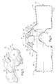
- a liquid/vapor separator assembly 10 for a fuel tank 12 of a vehicle (not shown).
- the fuel tank 12 includes a bottom wall 14 and a side wall 16 around a periphery of the bottom wall 14 and extending generally perpendicular thereto.
- the fuel tank 12 also includes a top wall 18 around a periphery of the side wall 16 and extending generally perpendicular thereto and generally parallel to the bottom wall 14 to form an interior chamber 19 to hold fuel therein.
- the fuel tank 12 is made of a rigid material such as plastic. It should be appreciated that fuel tank 12 is formed from two half shells that are welded together as is known in the art.
- the top wall 18 has a first base portion 20 extending toward the bottom wall 14 and a first side portion 22 extending upwardly and away at an angle from the first base portion 20.
- the top wall 18 also has a second base portion 24 extending from the first side portion 22 and generally parallel to the bottom wall 14.
- the top wall 18 further has a second side portion 26 extending upwardly and away at an angle from the second base portion 24.
- the top wall 18 has a third base portion 28 extending from the second side portion 26 and generally parallel to bottom wall 14.
- the top wall 18 also has a third side portion 30 extending upwardly from the base portion 20 and enclosing opposed sides of the portions 22,24,26,28.
- the top wall 18 is integral, unitary, and one-piece. It should be appreciated that the liquid/vapor separator assembly 10 uses the top wall 18 to form a part of the liquid/vapor separator.
- the liquid/vapor separator assembly 10 includes a liquid separator plate 32 attached to the top wall 18.
- the liquid separator plate 32 is generally rectangular in shape and of a size to be attached to the second base portion 24 of the top wall 18 by suitable means such as welding to form an integral liquid/vapor separator.
- the liquid separator plate 32 includes at least one, preferably a plurality of locators or projections 33 extending therefrom and through corresponding apertures in the second base portion 24 to locate the liquid separator plate 32 relative to the top wall 18.
- the liquid separator plate 32 includes at least one, preferably a plurality of drain apertures or channels (not shown) extending therethrough for liquid fuel to drain therethrough.
- the liquid separator plate 32 is made from a plastic material such as polyethylene, preferably a high-density polyethylene (HDPE), which is a conventional material known in the art. It should be appreciated that, when the liquid separator plate 32 is attached to the top wall 18 of the fuel tank 12, an integral liquid/vapor separator is formed. It should also be appreciated that, when the liquid separator plate 32 is attached to the top wall 18, a liquid trap 34 is formed between the liquid separator plate 32 and portions 26,28,30 of the top wall 18.
- HDPE high-density polyethylene
- the liquid/vapor separator assembly 10 also includes a fuel vapor tube or standpipe 35 extending through an aperture 36 in the liquid separator plate 32.
- the standpipe 35 is a tubular member with a generally circular cross-sectional shape and fluidly communicates with the liquid trap 34.
- the standpipe 35 allows fuel vapors that are separated to flow from the liquid trap 34 to a vapor canister (not shown) via a vent line connection to the canister attached to a lower end of the standpipe 35. It should be appreciated that an upper end of the standpipe 35 extends a predetermined distance above the liquid separator plate 32 to prevent liquid fuel from flowing to the vapor canister.
- the liquid/vapor separator assembly 10 also includes at least one valve 38,40 mounted to the liquid separator plate 32.
- the liquid/vapor separator assembly 10 includes a grade vent valve 38 mounted to the liquid separator plate 32.
- the grade vent valve 38 extends through a central aperture 40 in the liquid separator plate 32.
- the liquid/vapor separator assembly 10 includes a cylinder 42 disposed about the grade vent valve 38 and aperture 40 and secured to the liquid separator plate 32 by suitable means such as welding.
- the grade vent valve 38 has an annular flange 44 extending downwardly and attached to the cylinder 42 by suitable means such as welding. It should be appreciated that the cylinder 42 acts as a splash shield for liquid fuel.
- the liquid/vapor separator assembly 10 includes a fuel limiting vent valve 46 mounted to the liquid separator plate 32.
- the fuel limiting vent valve 46 is disposed in the interior chamber 19 and suspended by the liquid separator plate 32 via a connector 48 or connected directly to the liquid separator plate 32.
- the connector 48 extends through an aperture 50 in the liquid separator plate 32 to allow liquid fuel in the liquid trap 34 to drain through the connector 48 and fuel limiting vent valve 46 to the interior chamber 19 of the fuel tank 12.
- the liquid separator plate 32 integrates or incorporates mounting of the fuel limiting vent valve 46, grade vent valve 38, and standpipe 35 to separate liquid fuel.
- the liquid separator plate 32 acts as a mounting bracket for the fuel limiting vent valve 46 and grade vent valve 38.
- the valves 38 and 46 are conventional and known in the art.
- liquid fuel is disposed in the interior chamber 19 of the fuel tank 12.
- fuel may move and the liquid separator plate 32 separates liquid fuel from fuel vapor in the interior chamber 19. If liquid fuel condenses or is disposed in the liquid trap 34, the liquid fuel drains through the fuel limiting vent valve 46 or evaporates and goes to the vapor canister through the standpipe 34.
Landscapes
- Engineering & Computer Science (AREA)
- Life Sciences & Earth Sciences (AREA)
- Sustainable Development (AREA)
- Sustainable Energy (AREA)
- Chemical & Material Sciences (AREA)
- Combustion & Propulsion (AREA)
- Transportation (AREA)
- Mechanical Engineering (AREA)
- Cooling, Air Intake And Gas Exhaust, And Fuel Tank Arrangements In Propulsion Units (AREA)
- Supplying Secondary Fuel Or The Like To Fuel, Air Or Fuel-Air Mixtures (AREA)
Applications Claiming Priority (2)
| Application Number | Priority Date | Filing Date | Title |
|---|---|---|---|
| US931063 | 2001-08-16 | ||
| US09/931,063 US6520200B1 (en) | 2001-08-16 | 2001-08-16 | Liquid/vapor separator assembly for fuel tank |
Publications (1)
| Publication Number | Publication Date |
|---|---|
| EP1285804A1 true EP1285804A1 (fr) | 2003-02-26 |
Family
ID=25460171
Family Applications (1)
| Application Number | Title | Priority Date | Filing Date |
|---|---|---|---|
| EP20020077974 Withdrawn EP1285804A1 (fr) | 2001-08-16 | 2002-07-22 | Séparateur de liquide/vapeur pour réservoir de carburant |
Country Status (2)
| Country | Link |
|---|---|
| US (1) | US6520200B1 (fr) |
| EP (1) | EP1285804A1 (fr) |
Cited By (1)
| Publication number | Priority date | Publication date | Assignee | Title |
|---|---|---|---|---|
| EP1655476A3 (fr) * | 2004-11-05 | 2011-06-08 | Briggs & Stratton Corporation | Réservoir de carburant intégré avec un système de confinement des vapeurs |
Families Citing this family (8)
| Publication number | Priority date | Publication date | Assignee | Title |
|---|---|---|---|---|
| US6557581B2 (en) * | 2001-03-01 | 2003-05-06 | Raviv Precision Injection Molding | Liquid fuel trap |
| US6814771B2 (en) * | 2001-11-30 | 2004-11-09 | Delphi Technologies, Inc. | Evaporative emissions control device with internal seals |
| JP4905312B2 (ja) * | 2007-10-01 | 2012-03-28 | 日産自動車株式会社 | 燃料タンク装置 |
| KR100969388B1 (ko) * | 2008-08-14 | 2010-07-09 | 현대자동차주식회사 | 차량의 연료 공급 시스템 |
| US8215290B2 (en) * | 2008-10-03 | 2012-07-10 | Stant Usa Corp. | Marine carbon canister |
| US9222487B2 (en) | 2012-11-30 | 2015-12-29 | Caterpillar Inc. | Tank breather assembly and mounting configuration |
| WO2015087320A1 (fr) * | 2013-12-09 | 2015-06-18 | Raval A.C.S. Ltd. | Dispositif de vidange |
| RU2691539C2 (ru) | 2014-09-29 | 2019-06-14 | РАВАЛ Эй.Си.Эс. ЛТД. | Сливное устройство, способ обеспечения сливного устройства, сливная трубка и топливная система транспортного средства, содержащая упомянутое сливное устройство |
Citations (1)
| Publication number | Priority date | Publication date | Assignee | Title |
|---|---|---|---|---|
| US6182693B1 (en) * | 1999-06-08 | 2001-02-06 | Delphi Technologies, Inc. | Vapor canister and fuel tank assembly |
Family Cites Families (5)
| Publication number | Priority date | Publication date | Assignee | Title |
|---|---|---|---|---|
| DE1175097B (de) * | 1961-10-12 | 1964-07-30 | Daimler Benz Ag | Vorrichtung zur Entlueftung von Kraftstoff-behaeltern, insbesondere fuer Kraftfahrzeuge |
| US4852761A (en) * | 1988-07-25 | 1989-08-01 | General Motors Corporation | In tank vapor storage canister |
| BE1012390A3 (fr) * | 1999-01-18 | 2000-10-03 | Solvay | Systeme de mise a l'air de reservoir a liquide. |
| FR2811648B1 (fr) * | 2000-07-13 | 2002-09-27 | Solvay Automotive Fuel Systems | Systeme de mise a l'air d'un reservoir a liquide |
| US6557581B2 (en) * | 2001-03-01 | 2003-05-06 | Raviv Precision Injection Molding | Liquid fuel trap |
-
2001
- 2001-08-16 US US09/931,063 patent/US6520200B1/en not_active Expired - Fee Related
-
2002
- 2002-07-22 EP EP20020077974 patent/EP1285804A1/fr not_active Withdrawn
Patent Citations (1)
| Publication number | Priority date | Publication date | Assignee | Title |
|---|---|---|---|---|
| US6182693B1 (en) * | 1999-06-08 | 2001-02-06 | Delphi Technologies, Inc. | Vapor canister and fuel tank assembly |
Cited By (1)
| Publication number | Priority date | Publication date | Assignee | Title |
|---|---|---|---|---|
| EP1655476A3 (fr) * | 2004-11-05 | 2011-06-08 | Briggs & Stratton Corporation | Réservoir de carburant intégré avec un système de confinement des vapeurs |
Also Published As
| Publication number | Publication date |
|---|---|
| US6520200B1 (en) | 2003-02-18 |
| US20030034069A1 (en) | 2003-02-20 |
Similar Documents
| Publication | Publication Date | Title |
|---|---|---|
| US7383825B2 (en) | Small engine fuel tank with integrated evaporative controls | |
| US6182693B1 (en) | Vapor canister and fuel tank assembly | |
| EP0413531B1 (fr) | Pièce de fermeture pour réservoir de carburant | |
| US6866058B1 (en) | Fuel tank vent system with liquid fuel filter | |
| US20030098063A1 (en) | Outflow-limiting device of fuel tank | |
| US6543426B1 (en) | Multilayer fuel tank with cover and fuel vapor collection chamber | |
| US8844754B2 (en) | Fuel tank having a built-in auxiliary tank | |
| JP2003227429A (ja) | 燃料タンクから蒸発燃料を排出するためのシステムと、その方法 | |
| US6520200B1 (en) | Liquid/vapor separator assembly for fuel tank | |
| US7213583B2 (en) | Small engine fuel tank with integrated evaporative controls | |
| US11059368B2 (en) | Fill limit venting valve with high shut-off height | |
| US7228847B2 (en) | Cover assembly for fuel tank | |
| US6553973B1 (en) | Fuel tank cover and filter assembly for fuel tank | |
| EP1495897B1 (fr) | Pompe à combustible modulaire avec un collecteur d'évacuation de vapeurs | |
| EP1314604A1 (fr) | Elément de couverture avec module d'acheminement de carburant | |
| EP1108883B1 (fr) | Système d'alimentation en carburant | |
| US6361691B1 (en) | Floated fuel strainer assembly for a fuel tank | |
| GB2238041A (en) | Fuel tank venting | |
| EP1488947A2 (fr) | Système de ventilation pour réservoir de carburant avec filtre pour combustible liquide | |
| EP1262354B1 (fr) | Module de trappe d'obturation de réservoir pour véhicules à moteur | |
| US6959721B2 (en) | Cover assembly for fuel delivery module | |
| EP1063117A2 (fr) | Dispositif de récupération et de contrôle de vapeur de carburant pour un réservoir d'un véhicule | |
| US20140174070A1 (en) | Liquid and air separator | |
| EP0945299B1 (fr) | Ventilation d'un réservoir de carburant | |
| JP2001206079A (ja) | 燃料タンクの給油口 |
Legal Events
| Date | Code | Title | Description |
|---|---|---|---|
| PUAI | Public reference made under article 153(3) epc to a published international application that has entered the european phase |
Free format text: ORIGINAL CODE: 0009012 |
|
| AK | Designated contracting states |
Kind code of ref document: A1 Designated state(s): AT BE BG CH CY CZ DE DK EE ES FI FR GB GR IE IT LI LU MC NL PT SE SK TR Designated state(s): AT BE BG CH CY CZ DE DK EE ES FI FR GB GR IE IT LI LU MC NL PT SE SK TR |
|
| AX | Request for extension of the european patent |
Extension state: AL LT LV MK RO SI |
|
| 17P | Request for examination filed |
Effective date: 20030826 |
|
| AKX | Designation fees paid |
Designated state(s): AT DE FR GB |
|
| D17P | Request for examination filed (deleted) | ||
| DBV | Designated contracting states (deleted) | ||
| REG | Reference to a national code |
Ref country code: DE Ref legal event code: 8566 |
|
| 17Q | First examination report despatched |
Effective date: 20031204 |
|
| STAA | Information on the status of an ep patent application or granted ep patent |
Free format text: STATUS: THE APPLICATION IS DEEMED TO BE WITHDRAWN |
|
| 18D | Application deemed to be withdrawn |
Effective date: 20030827 |
|
| R17P | Request for examination filed (corrected) |
Effective date: 20030826 |