EP1314604A1 - Elément de couverture avec module d'acheminement de carburant - Google Patents
Elément de couverture avec module d'acheminement de carburant Download PDFInfo
- Publication number
- EP1314604A1 EP1314604A1 EP02079499A EP02079499A EP1314604A1 EP 1314604 A1 EP1314604 A1 EP 1314604A1 EP 02079499 A EP02079499 A EP 02079499A EP 02079499 A EP02079499 A EP 02079499A EP 1314604 A1 EP1314604 A1 EP 1314604A1
- Authority
- EP
- European Patent Office
- Prior art keywords
- cover
- cover assembly
- extending
- vent port
- set forth
- Prior art date
- Legal status (The legal status is an assumption and is not a legal conclusion. Google has not performed a legal analysis and makes no representation as to the accuracy of the status listed.)
- Withdrawn
Links
- 239000000446 fuel Substances 0.000 title claims description 48
- 239000002828 fuel tank Substances 0.000 claims abstract description 49
- 238000013022 venting Methods 0.000 claims abstract description 10
- 230000014759 maintenance of location Effects 0.000 description 6
- OKTJSMMVPCPJKN-UHFFFAOYSA-N Carbon Chemical compound [C] OKTJSMMVPCPJKN-UHFFFAOYSA-N 0.000 description 2
- 230000033228 biological regulation Effects 0.000 description 2
- 229910052799 carbon Inorganic materials 0.000 description 2
- 239000000945 filler Substances 0.000 description 2
- 239000000463 material Substances 0.000 description 2
- 238000000034 method Methods 0.000 description 2
- 238000003466 welding Methods 0.000 description 2
- 239000004215 Carbon black (E152) Substances 0.000 description 1
- 239000003610 charcoal Substances 0.000 description 1
- 229930195733 hydrocarbon Natural products 0.000 description 1
- 150000002430 hydrocarbons Chemical class 0.000 description 1
- 238000001746 injection moulding Methods 0.000 description 1
- 238000004519 manufacturing process Methods 0.000 description 1
- 230000013011 mating Effects 0.000 description 1
- 238000012986 modification Methods 0.000 description 1
- 230000004048 modification Effects 0.000 description 1
- 238000000465 moulding Methods 0.000 description 1
- 238000007789 sealing Methods 0.000 description 1
Images


Classifications
-
- B—PERFORMING OPERATIONS; TRANSPORTING
- B60—VEHICLES IN GENERAL
- B60K—ARRANGEMENT OR MOUNTING OF PROPULSION UNITS OR OF TRANSMISSIONS IN VEHICLES; ARRANGEMENT OR MOUNTING OF PLURAL DIVERSE PRIME-MOVERS IN VEHICLES; AUXILIARY DRIVES FOR VEHICLES; INSTRUMENTATION OR DASHBOARDS FOR VEHICLES; ARRANGEMENTS IN CONNECTION WITH COOLING, AIR INTAKE, GAS EXHAUST OR FUEL SUPPLY OF PROPULSION UNITS IN VEHICLES
- B60K15/00—Arrangement in connection with fuel supply of combustion engines or other fuel consuming energy converters, e.g. fuel cells; Mounting or construction of fuel tanks
- B60K15/03—Fuel tanks
- B60K15/035—Fuel tanks characterised by venting means
- B60K15/03519—Valve arrangements in the vent line
-
- B—PERFORMING OPERATIONS; TRANSPORTING
- B60—VEHICLES IN GENERAL
- B60K—ARRANGEMENT OR MOUNTING OF PROPULSION UNITS OR OF TRANSMISSIONS IN VEHICLES; ARRANGEMENT OR MOUNTING OF PLURAL DIVERSE PRIME-MOVERS IN VEHICLES; AUXILIARY DRIVES FOR VEHICLES; INSTRUMENTATION OR DASHBOARDS FOR VEHICLES; ARRANGEMENTS IN CONNECTION WITH COOLING, AIR INTAKE, GAS EXHAUST OR FUEL SUPPLY OF PROPULSION UNITS IN VEHICLES
- B60K15/00—Arrangement in connection with fuel supply of combustion engines or other fuel consuming energy converters, e.g. fuel cells; Mounting or construction of fuel tanks
- B60K15/03—Fuel tanks
- B60K15/03177—Fuel tanks made of non-metallic material, e.g. plastics, or of a combination of non-metallic and metallic material
Definitions
- the present invention relates generally to fuel tanks for vehicles and, more particularly, to a cover assembly for a fuel delivery module in a fuel tank of a vehicle.
- a fuel tank in a vehicle to hold fuel to be used by an engine of the vehicle.
- a cover is provided for a fuel delivery module to seal the opening through which the fuel delivery module has been assembled into the fuel tank.
- the fuel delivery module consists only of a cover/flange to which either an electrical fuel pump and/or a mechanism for indicating fuel is attached.
- the trend has been to construct fuel delivery modules with an integral reservoir.
- Various valves, sensors, pressure regulators, as well as filters have been added over time.
- a fuel limiting vent valve and other vent valves required for venting the fuel tank are mounted in the fuel tank and then plumbed together external to the fuel tank and vented to the vehicle carbon canister.
- a cover assembly for a fuel delivery module of a fuel tank to serve as a vent manifold for all connections for venting of the fuel tank. It is also desirable to provide a cover assembly for a fuel delivery module of a fuel tank that reduces vehicle emissions for a fuel tank. It is further desirable to provide a cover assembly for a fuel delivery module of a fuel tank, which reduces external parts with the fuel tank and cost.
- the present invention is a cover assembly for a fuel delivery module in a fuel tank of a vehicle including a cover adapted to close an opening in the fuel tank and a common vent port extending from the cover.
- the cover assembly also includes a plurality of valves attached to the cover and venting through the common vent port.
- a new cover assembly is provided for a fuel delivery module in a fuel tank of a vehicle that reduces vehicle emissions by eliminating the mounting of a fuel limiting vent valve separately in the fuel tank.
- the cover assembly serves as a vent manifold through which all connections for venting the fuel tank are made.
- the cover assembly allows all connections through the cover and reduces vehicle emissions by eliminating external fuel lines, connections, and mating interfaces with the fuel tank.
- the cover assembly can also be used to house and retain a fuel limiting vent valve and rollover valve which vents in line with the fuel limiting vent valve.
- the cover assembly reduces cost by reducing the number of parts.
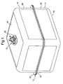
- the fuel tank 12 includes a first or lower half shell 14 and a second or upper half shell 16.
- the lower half shell 14 has a base wall 18 and a side wall 20 around a periphery of the base wall 18 and extending generally perpendicular thereto.
- the side wall 20 has a flange 22 extending outwardly and generally perpendicular thereto.
- the upper half shell 16 has a base wall 24 and a side wall 26 around a periphery of the base wall 24 and extending generally perpendicular thereto.
- the side wall 26 has a flange 28 extending outwardly and generally perpendicular thereto.
- the flanges 22 and 28 of the lower half shell 14 and upper half shell 16, respectively, are joined together by suitable means such as by welding.
- the lower half shell 14 and upper half shell 16 are made of a rigid material such as plastic.
- the base wall 24 of the upper half shell 16 includes an opening 30 for the cover assembly 10. It should be appreciated that, except for the cover assembly 10, the fuel tank 12 is conventional and known in the art.
- the cover assembly 10 is part of a fuel delivery module, generally indicated at 32.
- the fuel delivery module 32 is disposed in the fuel tank 12 to delivery fuel from the fuel tank 12 to an engine (not shown) of the vehicle.
- the fuel delivery module 32 includes a reservoir assembly 34 having an electrical fuel pump 36 mounted therein.
- the fuel delivery module 32 also includes a fuel level indication device 38 such as a rheostat connected to the reservoir assembly 34 for indicating the level of the fuel inside the fuel tank 12.
- the fuel delivery module 32 further includes a plurality of guide rods or tubes 40 to mechanically connect the cover assembly 10 with the reservoir assembly 34. It should be appreciated that, in other types of fuel delivery modules, there is no mechanical connection between the cover assembly 10 and the reservoir assembly 34 and this type of module requires a retaining mechanism on the bottom of the fuel tank 12.
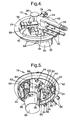
- the cover assembly 10 includes a cover 42 to cover or close the opening 30.
- the cover 42 is generally circular in shape.
- the cover 42 includes a base wall 44 having a raised portion 46.
- the raised portion 46 has at least one, preferably a plurality of apertures 48,50 extending therethrough for a function to be described.
- the cover 42 further includes a skirt or side wall 52 extending generally perpendicular and axially from the base wall 44.
- the cover 42 is made from a rigid material such as plastic.
- the cover 42 also has a first step 54 that is generally circular in shape and extending axially from the raised portion 46 to provide a support surface for an o-ring (not shown).
- the cover 42 also has a second step 56 that is generally circular in shape and extending axially from the raised portion 46 to provide a support surface for an o-ring (not shown).
- the cover 42 has an in series common vent port or tube 58 connected to the first step 54 and second step 56.
- the vent tube 58 extends radially from the first step 54 and second step 56.
- the vent tube 58 has a passageway 60 of a predetermined diameter such as 5/8 inches extending axially therethrough and communicating with the first step 54 and second step 56.
- the vent tube 58 also has a plurality of projections or barbs 62 extending radially outwardly for attachment to a conduit (not shown). It should be appreciated that the conduit is attached to a carbon canister (not shown).
- the cover 42 includes at least one, preferably a plurality of guide rod retaining bosses 64.
- the guide rod retaining bosses 64 are generally cylindrical and circular in shape.
- the guide rod retaining bosses 64 have a cavity 66 extending axially therein to receive and retain the guide rods 40.
- the guide rod retaining bosses 64 extend axially from the base wall 44 and raised portion 46 and may extend radially from the side wall 52. It should be appreciated that the guide rod retaining bosses 64 provide rotational flexibility in the attachment of the cover assembly 10 with the reservoir assembly 34.
- the cover 42 also includes an internal vent port or tube 68 extending toward the reservoir assembly 34.
- the internal vent tube 68 has one end connected to the first step 54 and extending downwardly at an angle to an enlarged end 70.
- the internal vent tube 68 has a passageway 72 extending axially therethrough and communicating with passageway 60 of the common vent tube 58. It should be appreciated that the internal vent tube 68 connects the rollover valve to the interior of the fuel tank 12.
- the cover 42 includes an external vent port or tube 74 extending outwardly therefrom.
- the external vent tube 74 has one end connected to the common vent tube 58 and extending radially to an enlarged end 76.
- the external vent tube 74 has a passageway 78 extending axially therethrough and communicating with the passageway 60 of the common vent tube 58. It should be appreciated that the external vent tube 74 is external to the fuel tank 12 and in line with the fuel limiting vent valve vent path to accept a vapor recirculation line (not shown) from a filler neck (not shown).
- the vapor recirculation line acts to reduce the vapors generated during the filling of the fuel tank 12 by reducing the amount of external air ingested into the filler neck by allowing for the recirculation of vapors vented through the fuel limiting vent valve.
- the external vent tube 74 is in line with the fuel limiting vent valve vent path to accept a remote mounted vent valve (not shown).
- the cover 42 may include at least one, preferably a plurality of retaining tabs 80 disposed about at least one of the apertures 50 for a function to be described.
- the cover 42 also includes a cylindrical wall 82 extending axially from an interior surface 84 of the raised portion 62 for a function to be described.
- the cover 42 further includes at least one, preferably a plurality of retention tabs 86 with each having an aperture or window 88 extending therethrough.
- the retention tabs 86 are disposed about the aperture and extend axially for a function to be described. It should be appreciated that the cover 42 is a monolithic structure being integral, unitary, and one-piece.
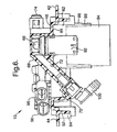
- the cover assembly 10 may include at least one, preferably a plurality of fuel tubes 90 extending into and through the apertures 48 of the cover 42.
- the fuel tubes 90 are connected or assembled to the cover 42 by suitable means such as molding, but may be attached by other suitable means such as welding, or mechanical retention.
- the cover assembly 10 may include a rollover vent valve 92 extending into and through the aperture 50 of the cover 42.
- the rollover vent valve 92 is located a predetermined distance such as 6.8 millimeters above the raised portion 46 to maximize venting of the fuel tank 12.
- the cover assembly 10 may include a fill limiting vent valve 94 extending into and through the aperture 50 in the cover 42.
- the cylindrical wall 82 provides sealing for an o-ring 95 attached to the fill limiting vent valve 94.
- the retention tabs 86 provide mechanical retention of the fill limiting vent valve 94 when snaps of the fill limiting vent valve 94 latch into the windows 88.
- the cover assembly 10 may include an electrical connector 96 such as a four-way electrical connector extending into and through the aperture 50.
- the retaining tabs 80 provide retention for the electrical connector 96.
- the cover assembly 10 may include an on-board diagnostic sensor 98 extending into and through the aperture 50 for diagnostic purposes.
- the cover assembly 10 may include a quick connector 100 having a general "L" shape with one end disposed in the enlarged end 70 of the internal vent tube 68 and the other end for connection to a vapor line form a remote mounted rollover valve (not shown).
- valves 92 and 94 operate in series and vent to a charcoal canister (not shown) through the common vent tube 58. It should also be appreciated that the fuel tubes 90, rollover vent valve 92, fill limiting vent valve 94, electrical connector 96, and thermistor 98 are conventional and known in the art.
- the cover 42 is molded by conventional processes such as injection molding.
- the fuel tubes 90, rollover vent valve 92, fill limiting vent valve 94, electrical connector 96, thermistor 98, and quick connector 100 are assembled to the cover 42.
- the cover 42 is secured to the base wall 24 of the upper half shell 16 by suitable means. It should be appreciated that the process of securing the cover 42 to the base wall 24 is conventional and known in the art.
Landscapes
- Engineering & Computer Science (AREA)
- Life Sciences & Earth Sciences (AREA)
- Sustainable Development (AREA)
- Sustainable Energy (AREA)
- Chemical & Material Sciences (AREA)
- Combustion & Propulsion (AREA)
- Transportation (AREA)
- Mechanical Engineering (AREA)
- Cooling, Air Intake And Gas Exhaust, And Fuel Tank Arrangements In Propulsion Units (AREA)
Applications Claiming Priority (2)
| Application Number | Priority Date | Filing Date | Title |
|---|---|---|---|
| US992082 | 2001-11-19 | ||
| US09/992,082 US20030094458A1 (en) | 2001-11-19 | 2001-11-19 | Fuel delivery module cover assembly |
Publications (1)
| Publication Number | Publication Date |
|---|---|
| EP1314604A1 true EP1314604A1 (fr) | 2003-05-28 |
Family
ID=25537894
Family Applications (1)
| Application Number | Title | Priority Date | Filing Date |
|---|---|---|---|
| EP02079499A Withdrawn EP1314604A1 (fr) | 2001-11-19 | 2002-10-28 | Elément de couverture avec module d'acheminement de carburant |
Country Status (2)
| Country | Link |
|---|---|
| US (1) | US20030094458A1 (fr) |
| EP (1) | EP1314604A1 (fr) |
Cited By (3)
| Publication number | Priority date | Publication date | Assignee | Title |
|---|---|---|---|---|
| US7017607B2 (en) | 2003-05-02 | 2006-03-28 | Daimler Chrysler Ag | Expansion container for a fuel tank |
| WO2007120672A1 (fr) * | 2006-04-13 | 2007-10-25 | Continental Automotive Systems Us, Inc. | Interface à support à brides permettant la sélection d'emplacement de supports |
| EP1495897B2 (fr) † | 2003-07-09 | 2009-09-23 | Denso International America, Inc. | Pompe à combustible modulaire avec un collecteur d'évacuation de vapeurs |
Families Citing this family (9)
| Publication number | Priority date | Publication date | Assignee | Title |
|---|---|---|---|---|
| US7228847B2 (en) * | 2004-04-30 | 2007-06-12 | Delphi Technologies, Inc. | Cover assembly for fuel tank |
| KR100969388B1 (ko) * | 2008-08-14 | 2010-07-09 | 현대자동차주식회사 | 차량의 연료 공급 시스템 |
| US8459013B2 (en) * | 2008-12-30 | 2013-06-11 | Daimler Trucks North America Llc | Urea tank with closure member for vehicle exhaust system |
| BR112012031838B1 (pt) * | 2010-06-15 | 2020-12-08 | Shaw Development, Llc | combinação e unidade de cabeçote |
| US9428043B2 (en) * | 2013-11-07 | 2016-08-30 | Fca Us Llc | Liquid vapor separator drain valve |
| JP6212411B2 (ja) * | 2014-02-28 | 2017-10-11 | コベルコ建機株式会社 | 還元剤容器 |
| US10377229B2 (en) * | 2017-05-11 | 2019-08-13 | GM Global Technology Operations LLC | Fuel storage assembly for a vehicle |
| CN109532470B (zh) * | 2018-12-06 | 2021-07-16 | 泸州发展机械有限公司 | 一种金属燃油箱内置阀体装配机构 |
| CN114320673A (zh) * | 2020-10-09 | 2022-04-12 | 通用汽车环球科技运作有限责任公司 | 蒸发排放系统 |
Citations (4)
| Publication number | Priority date | Publication date | Assignee | Title |
|---|---|---|---|---|
| EP0790144A2 (fr) * | 1996-02-15 | 1997-08-20 | Borg-Warner Automotive, Inc. | Soupape de remplissage de carburant de véhicule |
| US5960817A (en) * | 1997-11-03 | 1999-10-05 | Walbro Corporation | Control valve and system for fuel vapor recovery |
| US5983958A (en) * | 1994-08-24 | 1999-11-16 | G.T. Products, Inc. | Onboard vapor recovery system with two stage shutoff valve |
| US6213100B1 (en) * | 1999-04-28 | 2001-04-10 | Walbro Corporation | Multi-function fuel pump module |
-
2001
- 2001-11-19 US US09/992,082 patent/US20030094458A1/en not_active Abandoned
-
2002
- 2002-10-28 EP EP02079499A patent/EP1314604A1/fr not_active Withdrawn
Patent Citations (4)
| Publication number | Priority date | Publication date | Assignee | Title |
|---|---|---|---|---|
| US5983958A (en) * | 1994-08-24 | 1999-11-16 | G.T. Products, Inc. | Onboard vapor recovery system with two stage shutoff valve |
| EP0790144A2 (fr) * | 1996-02-15 | 1997-08-20 | Borg-Warner Automotive, Inc. | Soupape de remplissage de carburant de véhicule |
| US5960817A (en) * | 1997-11-03 | 1999-10-05 | Walbro Corporation | Control valve and system for fuel vapor recovery |
| US6213100B1 (en) * | 1999-04-28 | 2001-04-10 | Walbro Corporation | Multi-function fuel pump module |
Cited By (4)
| Publication number | Priority date | Publication date | Assignee | Title |
|---|---|---|---|---|
| US7017607B2 (en) | 2003-05-02 | 2006-03-28 | Daimler Chrysler Ag | Expansion container for a fuel tank |
| EP1495897B2 (fr) † | 2003-07-09 | 2009-09-23 | Denso International America, Inc. | Pompe à combustible modulaire avec un collecteur d'évacuation de vapeurs |
| WO2007120672A1 (fr) * | 2006-04-13 | 2007-10-25 | Continental Automotive Systems Us, Inc. | Interface à support à brides permettant la sélection d'emplacement de supports |
| US7690359B2 (en) | 2006-04-13 | 2010-04-06 | Continental Automotive Systems Us, Inc. | Flange-strut interface permitting location selection of struts |
Also Published As
| Publication number | Publication date |
|---|---|
| US20030094458A1 (en) | 2003-05-22 |
Similar Documents
| Publication | Publication Date | Title |
|---|---|---|
| US6182693B1 (en) | Vapor canister and fuel tank assembly | |
| EP1320468B1 (fr) | Montage d'une combinaison de pompe a carburant, transmetteur de niveau et soupape de retenue/mise a l'air libre dans un reservoir a carburant | |
| US5704337A (en) | Fuel tank | |
| US7047948B2 (en) | Fuel tank | |
| EP1705051B1 (fr) | Clapet pour la ventilation d'un réservoir de carburant liquide | |
| US7383825B2 (en) | Small engine fuel tank with integrated evaporative controls | |
| EP1314604A1 (fr) | Elément de couverture avec module d'acheminement de carburant | |
| US6450152B1 (en) | Low-profile fuel tank isolation valve | |
| US7228847B2 (en) | Cover assembly for fuel tank | |
| US6179145B1 (en) | Serviceable sealed fuel tank | |
| US7121301B2 (en) | Fuel tank | |
| US20030056837A1 (en) | Controlling fuel tank vapor venting during refueling | |
| US7213583B2 (en) | Small engine fuel tank with integrated evaporative controls | |
| US20060196481A1 (en) | Evaporative emission control system and method for small engines | |
| US6581578B2 (en) | Fuel delivery and ventilation system | |
| US7185638B2 (en) | Fuel tank for a motor vehicle | |
| CN108349380B (zh) | 无盖供油装置及其制造方法 | |
| US20060032663A1 (en) | Lid of fuel tank | |
| EP1262354B1 (fr) | Module de trappe d'obturation de réservoir pour véhicules à moteur | |
| CN105555576B (zh) | 用于给燃料储箱通气的方法和阀门 | |
| US6807978B2 (en) | Cover assembly for fuel delivery module | |
| US7268301B2 (en) | Lid of fuel tank | |
| US20140209194A1 (en) | Support arm assembly | |
| US20060260696A1 (en) | Fuel delivery and vapor control system | |
| CN209977278U (zh) | 一种新型电控阀总成 |
Legal Events
| Date | Code | Title | Description |
|---|---|---|---|
| PUAI | Public reference made under article 153(3) epc to a published international application that has entered the european phase |
Free format text: ORIGINAL CODE: 0009012 |
|
| AK | Designated contracting states |
Designated state(s): AT BE BG CH CY CZ DE DK EE ES FI FR GB GR IE IT LI LU MC NL PT SE SK TR |
|
| AX | Request for extension of the european patent |
Extension state: AL LT LV MK RO SI |
|
| AKX | Designation fees paid | ||
| REG | Reference to a national code |
Ref country code: DE Ref legal event code: 8566 |
|
| STAA | Information on the status of an ep patent application or granted ep patent |
Free format text: STATUS: THE APPLICATION IS DEEMED TO BE WITHDRAWN |
|
| 18D | Application deemed to be withdrawn |
Effective date: 20031129 |