EP1285822A2 - Dispositif d'airbag pour véhicule automobile - Google Patents
Dispositif d'airbag pour véhicule automobile Download PDFInfo
- Publication number
- EP1285822A2 EP1285822A2 EP02014382A EP02014382A EP1285822A2 EP 1285822 A2 EP1285822 A2 EP 1285822A2 EP 02014382 A EP02014382 A EP 02014382A EP 02014382 A EP02014382 A EP 02014382A EP 1285822 A2 EP1285822 A2 EP 1285822A2
- Authority
- EP
- European Patent Office
- Prior art keywords
- wall
- head impact
- channel
- impact element
- bead
- Prior art date
- Legal status (The legal status is an assumption and is not a legal conclusion. Google has not performed a legal analysis and makes no representation as to the accuracy of the status listed.)
- Granted
Links
Images


Classifications
-
- B—PERFORMING OPERATIONS; TRANSPORTING
- B60—VEHICLES IN GENERAL
- B60R—VEHICLES, VEHICLE FITTINGS, OR VEHICLE PARTS, NOT OTHERWISE PROVIDED FOR
- B60R21/00—Arrangements or fittings on vehicles for protecting or preventing injuries to occupants or pedestrians in case of accidents or other traffic risks
- B60R21/02—Occupant safety arrangements or fittings, e.g. crash pads
- B60R21/16—Inflatable occupant restraints or confinements designed to inflate upon impact or impending impact, e.g. air bags
- B60R21/20—Arrangements for storing inflatable members in their non-use or deflated condition; Arrangement or mounting of air bag modules or components
- B60R21/217—Inflation fluid source retainers, e.g. reaction canisters; Connection of bags, covers, diffusers or inflation fluid sources therewith or together
- B60R21/2171—Inflation fluid source retainers, e.g. reaction canisters; Connection of bags, covers, diffusers or inflation fluid sources therewith or together specially adapted for elongated cylindrical or bottle-like inflators with a symmetry axis perpendicular to the main direction of bag deployment, e.g. extruded reaction canisters
-
- B—PERFORMING OPERATIONS; TRANSPORTING
- B60—VEHICLES IN GENERAL
- B60R—VEHICLES, VEHICLE FITTINGS, OR VEHICLE PARTS, NOT OTHERWISE PROVIDED FOR
- B60R21/00—Arrangements or fittings on vehicles for protecting or preventing injuries to occupants or pedestrians in case of accidents or other traffic risks
- B60R21/02—Occupant safety arrangements or fittings, e.g. crash pads
- B60R21/04—Padded linings for the vehicle interior ; Energy absorbing structures associated with padded or non-padded linings
- B60R21/045—Padded linings for the vehicle interior ; Energy absorbing structures associated with padded or non-padded linings associated with the instrument panel or dashboard
Definitions
- the invention relates to an airbag device for a motor vehicle according to the Preamble of claim 1.
- An airbag device is known from EP 0 728 628 A2, which has a generator housing with walls for a firing channel of an airbag.
- a front wall of the Shot channel is formed from two releasably connected individual walls, the separable from each other in a head impact or in a load position are.
- the object of the invention is to provide an improved airbag device for a motor vehicle create an easy mounting in the vehicle as well as an unhindered and guided wall lowering of a channel wall of the firing channel in the event of a head impact or guaranteed in a load position.
- the main advantages achieved with the invention are that by Using a pivotally held on the generator housing Head impact element, this can be lowered immediately in a load position without disability or is pivotable and thus injuries to the head of a vehicle occupant are largely avoided.
- the vehicle occupant is in a first Trimmed channel wall of the generator housing a head impact element in bearings arranged pivotably on one side and in the second one below Channel wall of the housing, the head impact element in a starting position via a clamping connection can be hooked in and unclipped in a load position.
- the head impact element consists essentially of a U-shaped bracket with legs mounted on the first channel wall of the housing, which have a web part are interconnected, which forms a complementary upper channel wall, which as Connection of a receiving channel for a molded hook strip on the second Has channel wall of the housing.
- the pivotably articulated bracket can be used for one React head-on immediately and there will be delays, for example a deformation caused after the establishment acc. EP 0 728 628 A2 avoided.
- connection between the head impact element and the wall of the Generator housing can be designed as a positive connection for example, the receiving channel has a correspondingly shaped corresponding one Has hook strip.
- a pronounced retaining bead is also conceivable according to the invention, which in The load position is held in a clamped manner in an embossed receiving bead becomes.
- the receiving bead in the wall of the generator housing is approximately in cross section W-shaped with two notches and an upper edge of the wall of the Generator housing is angled outwards, corresponding to Receiving bead, the retaining bead of the channel wall in the receiving bead, clamping is held.
- the upper channel wall of the Head impact element about an approximately horizontal formed by the bearings Swivel axis in relation to the stationary second duct wall of the generator housing
- the load case can be swung down by unlatching the positive connection. This ensures in particular that the head of a vehicle occupant, especially of a passenger not on a fixed edge of a firing channel wall hits, but this hard edge moves into the device under load or pivoted and thus a reduction in the surcharge takes place. Furthermore, by untying the connection between the head impact element and the Wall of the generator housing also dissipated energy.
- the generator housing is held on the end brackets and fasteners these are stiff over parked angles with a support of the vehicle body connected.
- the connection to the carrier should be relatively rigid, so all loads, such as vibrations are absorbed during the shot and one Deformability cannot occur when the head is turned up.
- Mounting brackets are connected to the generator housing, via which the Airbag device is deformably attached to a control panel of the vehicle. By this additional deformation of the mounting bracket will dissipate additional energy. This plastic deformation is also used to create a Allow deformation.
- the wall of the generator housing has an almost smooth-walled, flat firing channel, where on the second channel wall of the generator housing the upper position Channel wall of the head impact element is supported.
- the end walls of the firing channel are on the one hand through the legs of the Head impact element and on the other hand formed by the brackets, whereby each a complementary joint continuous and raised at the corners front channel wall results.
- the design according to the invention ensures good guidance of the airbag and a quick rejection of the airbag achieved under load. Furthermore, to fulfill the Head impact in the area of the control panel achieved an easily deformable firing channel. To meet these two requirements, the two parts of the invention Shot channel provided. This two-part system has the main advantage that the Corner areas of the firing channel are defused. The corner areas can now also be used a force are applied in the load case and evade, so that none Voltage peaks can occur more.
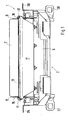
- An airbag device 1 essentially comprises a generator housing 2, which in Transverse direction in the vehicle below a cover 3 of a control panel 3a or one Cockpit of a motor vehicle is arranged.
- This housing 2 has a molded first integrated rear wall 4 and another molded second front wall 5-in In relation to a vehicle occupant or in relation to the direction of travel F of the vehicle - to form a firing channel 6 for an airbag 7, which is shown schematically.
- This firing channel is closed at the end of the device 1 by brackets 8, 9.
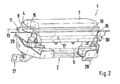
- the generator housing 2 is a so-called head impact element 10 in bearings 11, 12 pivotally connected about a pivot axis 13.
- the head impact element 10 consists of a U-shaped bracket with lateral Legs 15, 16, the ends of the bearings 11, 12 on the rear wall 4 of the Generator housing 2 are pivotable. These legs 15, 16 are via a web part 17th connected with each other. This forms the front duct wall 5 of the generator housing 2 an upper additional channel wall 17a.
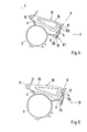
- connection K1; K2; K3; K4 connected to each other in such a way that in the starting position I a fixed but detachable connection K1, K2; K4 or an elastic spring connection K3 will be produced; on the other hand takes place at a load position II by swiveling the Head impact element 10 in the direction of arrow Z pivoting and thus untying or loosening the connection K1 and K2; K4.
- the connection K1 between the front Channel walls 5 and 17a are made by means of a quasi-positive connection between a so-called receiving channel 20 in the wall 5 and a corresponding one Hook bar 21 in the wall 17a.
- the receiving groove 20 of the wall 5 has an arcuate cross section Receiving mouth into which the corresponding hook strip 21 of the wall 17a in the Starting position I is held clamped.
- the hook strip 21 links itself out of the receiving channel 20.
- the bead 22 is released from the bead 23 and thus the head impact element can lower towards the wall 5.
- the receiving bead in the wall has approximately a W shape with two in cross section distinctive click beads.
- the two edges R1 and R2 of the receiving bead 23 are parked outside.
- the holding bead is corresponding to the receiving bead 23 22 of the head impact element 10 also in cross section W-shaped with two corresponding resting seats as the receiving bead 23 executed.
- the edge of the R1 Receiving bead 23 forms an upper stop and a parked section R2 the holding bead 22, which is located over this section R2 on the parked edge section R1 supported.
- connection K3 exists between the Wall 5 of the generator housing 2 and the wall 17a of the head impact element 10 a spring element 24 or a plurality of spring elements 24. These are for example between positions 25 and 26 of element 10 and wall 5 arranged.
- the head impact element 10 in the direction of the arrow Z Swivel axis 13 pivoted downward, so that the wall 17a on the outside or Moved inside to wall 5.
- the airbag device 1 is attached to the carrier of the body structure via the end brackets 8, 9 with the generator housing 2 via fasteners get connected.
- a connection of the brackets 8, 9 to the carriers or the carrier takes place via parked angles 27, 28.
- the connection of the brackets 8, 9 be rigid and rigid with the support.
- the connection should the fastening means 29, 30 of the device 1 with the control panel or the cockpit Absorb energy or be designed to be deformable.
- the front channel walls 5 and 17a of the firing channel for the airbag 7 complement each other in such a way that the roughly in the starting and load position I and II in about common plane X-X are arranged so that the airbag 7 in its movement is not hindered.
- load position II acc. 6 the upper channel wall 17a Support on the lower duct wall 5 in one area.
- brackets 8 and 9 complement each other with the Legs 14 and 15 of the head impact member 10 to form one at the corners raised shot channel.
- the web 17 has between the two legs 15, 16 of the head impact element 10 on at least two mounting eyelets 30 which are arranged at a distance b from one another. Between these eyelets 30 and above these eyelets 30 is the actual connection K4 of the web part 17 with the Channel wall 5 is provided.
- This connection K4 exists, as also in Fig. 9 closer is shown, from the receiving bead 23 and the retaining bead 22.
- the suspension eyes 30th are, as shown in Fig. 11 in more detail, with a distance a from the end of Head impact element 10 arranged, a between the two suspension eyes 30 Distance b is provided.
- These eyelets 30 are solely for holding on Head impact part 10 provided, whereas the connection K4 the actual Friction work caused by head impact.
Landscapes
- Engineering & Computer Science (AREA)
- Mechanical Engineering (AREA)
- Air Bags (AREA)
Applications Claiming Priority (2)
| Application Number | Priority Date | Filing Date | Title |
|---|---|---|---|
| DE10139593A DE10139593A1 (de) | 2001-08-11 | 2001-08-11 | Airbageinrichtung für ein Kraftfahrzeug |
| DE10139593 | 2001-08-11 |
Publications (3)
| Publication Number | Publication Date |
|---|---|
| EP1285822A2 true EP1285822A2 (fr) | 2003-02-26 |
| EP1285822A3 EP1285822A3 (fr) | 2003-09-17 |
| EP1285822B1 EP1285822B1 (fr) | 2005-11-30 |
Family
ID=7695210
Family Applications (1)
| Application Number | Title | Priority Date | Filing Date |
|---|---|---|---|
| EP02014382A Expired - Lifetime EP1285822B1 (fr) | 2001-08-11 | 2002-06-28 | Dispositif d'airbag pour véhicule automobile |
Country Status (5)
| Country | Link |
|---|---|
| US (1) | US6854761B2 (fr) |
| EP (1) | EP1285822B1 (fr) |
| JP (1) | JP2003072501A (fr) |
| AT (1) | ATE311315T1 (fr) |
| DE (2) | DE10139593A1 (fr) |
Cited By (1)
| Publication number | Priority date | Publication date | Assignee | Title |
|---|---|---|---|---|
| EP2004454A4 (fr) * | 2006-04-11 | 2010-02-03 | Honda Motor Co Ltd | Dispositif de gonflage d'airbag amortisseur |
Families Citing this family (3)
| Publication number | Priority date | Publication date | Assignee | Title |
|---|---|---|---|---|
| US7290788B2 (en) * | 2003-09-03 | 2007-11-06 | Visteon Global Technologies, Inc. | Airbag bracket |
| DE102004025716B4 (de) * | 2004-05-26 | 2011-08-18 | Continental Automotive GmbH, 30165 | Airbagmodul |
| DE102009018950A1 (de) * | 2009-04-25 | 2010-10-28 | Dr. Ing. H.C. F. Porsche Aktiengesellschaft | Airbaghalter |
Citations (1)
| Publication number | Priority date | Publication date | Assignee | Title |
|---|---|---|---|---|
| EP0728628A2 (fr) | 1995-02-23 | 1996-08-28 | Morton International, Inc. | Boîtier déformable pour sac gonflable |
Family Cites Families (12)
| Publication number | Priority date | Publication date | Assignee | Title |
|---|---|---|---|---|
| JP2528375B2 (ja) * | 1990-06-18 | 1996-08-28 | 本田技研工業株式会社 | 乗員保護用エアバッグ装置 |
| JPH05270345A (ja) * | 1992-03-25 | 1993-10-19 | Takata Kk | 助手席用エアバッグ装置 |
| JP3161086B2 (ja) * | 1992-10-16 | 2001-04-25 | タカタ株式会社 | 助手席用エアバッグ装置 |
| US5342082A (en) * | 1993-05-28 | 1994-08-30 | Morton International, Inc. | Airbag reaction canister having softened edges |
| US5425550A (en) * | 1994-02-04 | 1995-06-20 | Morton International, Inc. | Unperforated slide-in passenger side airbag module cushion cover |
| US5395133A (en) * | 1994-02-04 | 1995-03-07 | Morton International, Inc. | Air bag reaction canister having softened edges |
| US5533747A (en) * | 1995-06-15 | 1996-07-09 | Morton International, Inc. | Airbag module with collapsible side wall |
| US5791684A (en) * | 1996-08-01 | 1998-08-11 | Morton International, Inc. | Airbag reaction canister with collapsible side wall |
| US5718447A (en) * | 1996-09-10 | 1998-02-17 | Morton International, Inc. | Pressure relief in airbag module reaction canisters |
| DE19851975A1 (de) | 1998-11-11 | 2000-05-18 | Daimler Chrysler Ag | Airbagmodulgehäuse |
| DE29823235U1 (de) * | 1998-12-30 | 1999-04-29 | Trw Repa Gmbh | Fahrzeugsicherheitsvorrichtung zum Schutz der Füße des Insassen |
| US6336652B1 (en) * | 2000-11-10 | 2002-01-08 | Trw Vehicle Safety Systems Inc. | Deployment door for an air bag module |
-
2001
- 2001-08-11 DE DE10139593A patent/DE10139593A1/de not_active Withdrawn
-
2002
- 2002-06-28 AT AT02014382T patent/ATE311315T1/de active
- 2002-06-28 DE DE50205089T patent/DE50205089D1/de not_active Expired - Lifetime
- 2002-06-28 EP EP02014382A patent/EP1285822B1/fr not_active Expired - Lifetime
- 2002-08-09 US US10/215,193 patent/US6854761B2/en not_active Expired - Fee Related
- 2002-08-09 JP JP2002232907A patent/JP2003072501A/ja active Pending
Patent Citations (1)
| Publication number | Priority date | Publication date | Assignee | Title |
|---|---|---|---|---|
| EP0728628A2 (fr) | 1995-02-23 | 1996-08-28 | Morton International, Inc. | Boîtier déformable pour sac gonflable |
Cited By (2)
| Publication number | Priority date | Publication date | Assignee | Title |
|---|---|---|---|---|
| EP2004454A4 (fr) * | 2006-04-11 | 2010-02-03 | Honda Motor Co Ltd | Dispositif de gonflage d'airbag amortisseur |
| US8033566B2 (en) | 2006-04-11 | 2011-10-11 | Honda Motor Company | Impact absorbing airbag inflator |
Also Published As
| Publication number | Publication date |
|---|---|
| US20030042713A1 (en) | 2003-03-06 |
| US6854761B2 (en) | 2005-02-15 |
| EP1285822A3 (fr) | 2003-09-17 |
| ATE311315T1 (de) | 2005-12-15 |
| EP1285822B1 (fr) | 2005-11-30 |
| JP2003072501A (ja) | 2003-03-12 |
| DE10139593A1 (de) | 2003-02-27 |
| DE50205089D1 (de) | 2006-01-05 |
Similar Documents
| Publication | Publication Date | Title |
|---|---|---|
| DE19632222B4 (de) | Innenverkleidung für ein Fahrzeugdach | |
| DE10066268B4 (de) | Sicherheitssystem für ein Kraftfahrzeug | |
| DE3125687C2 (de) | Stoßfänger für Kraftfahrzeuge | |
| DE69204217T2 (de) | Verbesserungen von Luftsack-Aufprall-Schutzsystemen. | |
| EP3765351B1 (fr) | Dispositif de revêtement d'un bas de caisse d'un véhicule automobile et procédé pour faire fonctionner un tel dispositif de revêtement | |
| EP1262397B1 (fr) | Capot avant pour une voiture automobile | |
| DE2759029C2 (fr) | ||
| EP1053125B1 (fr) | Plage arriere comportant des pieces d'angle mobiles | |
| DE20118457U1 (de) | Seitengassackmodul für ein Fahrzeuginsassen-Schutzsystem | |
| EP1348585B1 (fr) | Panneau déplaçable pour toit de véhicule et module pour toit coulissant | |
| EP1285822A2 (fr) | Dispositif d'airbag pour véhicule automobile | |
| DE19847496A1 (de) | B-Säulen-Dachmodul | |
| EP3720737B1 (fr) | Élément d'habillage pour habiller une surface latérale d'un habitacle de véhicule ainsi que véhicule | |
| DE102004011786B4 (de) | Verfahren zum Erhöhen der Crashfestigkeit eines Kraftfahrzeugs und damit eingesetztes Blockelement | |
| EP4263252B1 (fr) | Véhicule, porte de véhicule et ensemble fenêtre pour celui-ci | |
| DE10309958A1 (de) | Kraftfahrzeug mit einer Fußgängerschutzeinrichtung sowie Verfahren zum Betreiben einer Fußgängerschutzeinrichtung an einem solchen Kraftfahrzeug | |
| WO2006069669A1 (fr) | Systeme d'airbag pour vehicules automobiles | |
| WO2020078717A1 (fr) | Véhicule automobile comprenant un coussin gonflable de sécurité pour piéton, couvercle de boîte à eau et structure de support associée | |
| EP2457758B1 (fr) | Capote d'un véhicule cabriolet dotée d'un dispositif de centrage destiné à la fixation sur un cadre de pare-brise ou sur un pillier A | |
| DE60003256T2 (de) | Verkleidungsanordnung für einen Kraftfahrzeugblechteil | |
| DE4007263A1 (de) | Anordnung zur loesbaren befestigung eines gepaecktraegers auf einem fahrzeugdach | |
| EP0952041B1 (fr) | Véhicule automobile avec au moins un filet de retenue à rouleau attachable entre les compartiments passagers et bagages | |
| DE3404785A1 (de) | Fahrbare arbeitsmaschine mit einem aufbau | |
| DE9012740U1 (de) | Vorbauanordnung für Nutzfahrzeuge, insbesondere für Omnibusse | |
| DE9416113U1 (de) | Trittaufsatz für Kraftfahrzeuge |
Legal Events
| Date | Code | Title | Description |
|---|---|---|---|
| PUAI | Public reference made under article 153(3) epc to a published international application that has entered the european phase |
Free format text: ORIGINAL CODE: 0009012 |
|
| AK | Designated contracting states |
Kind code of ref document: A2 Designated state(s): AT BE CH CY DE DK ES FI FR GB GR IE IT LI LU MC NL PT SE TR |
|
| AX | Request for extension of the european patent |
Extension state: AL LT LV MK RO SI |
|
| PUAL | Search report despatched |
Free format text: ORIGINAL CODE: 0009013 |
|
| AK | Designated contracting states |
Kind code of ref document: A3 Designated state(s): AT BE CH CY DE DK ES FI FR GB GR IE IT LI LU MC NL PT SE TR |
|
| AX | Request for extension of the european patent |
Extension state: AL LT LV MK RO SI |
|
| 17P | Request for examination filed |
Effective date: 20040317 |
|
| AKX | Designation fees paid |
Designated state(s): AT DE FR GB IT SE |
|
| 17Q | First examination report despatched |
Effective date: 20040527 |
|
| GRAP | Despatch of communication of intention to grant a patent |
Free format text: ORIGINAL CODE: EPIDOSNIGR1 |
|
| GRAS | Grant fee paid |
Free format text: ORIGINAL CODE: EPIDOSNIGR3 |
|
| GRAA | (expected) grant |
Free format text: ORIGINAL CODE: 0009210 |
|
| AK | Designated contracting states |
Kind code of ref document: B1 Designated state(s): AT DE FR GB IT SE |
|
| REG | Reference to a national code |
Ref country code: GB Ref legal event code: FG4D Free format text: NOT ENGLISH |
|
| REF | Corresponds to: |
Ref document number: 50205089 Country of ref document: DE Date of ref document: 20060105 Kind code of ref document: P |
|
| REG | Reference to a national code |
Ref country code: SE Ref legal event code: TRGR |
|
| GBT | Gb: translation of ep patent filed (gb section 77(6)(a)/1977) |
Effective date: 20060130 |
|
| ET | Fr: translation filed | ||
| PLBE | No opposition filed within time limit |
Free format text: ORIGINAL CODE: 0009261 |
|
| STAA | Information on the status of an ep patent application or granted ep patent |
Free format text: STATUS: NO OPPOSITION FILED WITHIN TIME LIMIT |
|
| 26N | No opposition filed |
Effective date: 20060831 |
|
| REG | Reference to a national code |
Ref country code: FR Ref legal event code: TP |
|
| PGFP | Annual fee paid to national office [announced via postgrant information from national office to epo] |
Ref country code: SE Payment date: 20090612 Year of fee payment: 8 |
|
| REG | Reference to a national code |
Ref country code: FR Ref legal event code: CD |
|
| EUG | Se: european patent has lapsed | ||
| REG | Reference to a national code |
Ref country code: FR Ref legal event code: TP |
|
| REG | Reference to a national code |
Ref country code: GB Ref legal event code: 732E Free format text: REGISTERED BETWEEN 20110310 AND 20110316 |
|
| REG | Reference to a national code |
Ref country code: GB Ref legal event code: 732E Free format text: REGISTERED BETWEEN 20110331 AND 20110406 |
|
| PGFP | Annual fee paid to national office [announced via postgrant information from national office to epo] |
Ref country code: FR Payment date: 20110630 Year of fee payment: 10 |
|
| PGFP | Annual fee paid to national office [announced via postgrant information from national office to epo] |
Ref country code: GB Payment date: 20110620 Year of fee payment: 10 |
|
| PGFP | Annual fee paid to national office [announced via postgrant information from national office to epo] |
Ref country code: IT Payment date: 20110623 Year of fee payment: 10 |
|
| PG25 | Lapsed in a contracting state [announced via postgrant information from national office to epo] |
Ref country code: SE Free format text: LAPSE BECAUSE OF NON-PAYMENT OF DUE FEES Effective date: 20100629 |
|
| GBPC | Gb: european patent ceased through non-payment of renewal fee |
Effective date: 20120628 |
|
| PG25 | Lapsed in a contracting state [announced via postgrant information from national office to epo] |
Ref country code: IT Free format text: LAPSE BECAUSE OF NON-PAYMENT OF DUE FEES Effective date: 20120628 |
|
| REG | Reference to a national code |
Ref country code: FR Ref legal event code: ST Effective date: 20130228 |
|
| PG25 | Lapsed in a contracting state [announced via postgrant information from national office to epo] |
Ref country code: FR Free format text: LAPSE BECAUSE OF NON-PAYMENT OF DUE FEES Effective date: 20120702 Ref country code: GB Free format text: LAPSE BECAUSE OF NON-PAYMENT OF DUE FEES Effective date: 20120628 |
|
| PGFP | Annual fee paid to national office [announced via postgrant information from national office to epo] |
Ref country code: AT Payment date: 20160621 Year of fee payment: 15 |
|
| PGFP | Annual fee paid to national office [announced via postgrant information from national office to epo] |
Ref country code: DE Payment date: 20160721 Year of fee payment: 15 |
|
| REG | Reference to a national code |
Ref country code: DE Ref legal event code: R119 Ref document number: 50205089 Country of ref document: DE |
|
| REG | Reference to a national code |
Ref country code: AT Ref legal event code: MM01 Ref document number: 311315 Country of ref document: AT Kind code of ref document: T Effective date: 20170628 |
|
| PG25 | Lapsed in a contracting state [announced via postgrant information from national office to epo] |
Ref country code: DE Free format text: LAPSE BECAUSE OF NON-PAYMENT OF DUE FEES Effective date: 20180103 |
|
| PG25 | Lapsed in a contracting state [announced via postgrant information from national office to epo] |
Ref country code: AT Free format text: LAPSE BECAUSE OF NON-PAYMENT OF DUE FEES Effective date: 20170628 |