EP1285875A1 - Vorrichtung zum Vereinigen von mindestens zwei Papierbahnen zu einem Papierstrang - Google Patents
Vorrichtung zum Vereinigen von mindestens zwei Papierbahnen zu einem Papierstrang Download PDFInfo
- Publication number
- EP1285875A1 EP1285875A1 EP01810073A EP01810073A EP1285875A1 EP 1285875 A1 EP1285875 A1 EP 1285875A1 EP 01810073 A EP01810073 A EP 01810073A EP 01810073 A EP01810073 A EP 01810073A EP 1285875 A1 EP1285875 A1 EP 1285875A1
- Authority
- EP
- European Patent Office
- Prior art keywords
- roller
- paper
- layer
- rollers
- outermost layer
- Prior art date
- Legal status (The legal status is an assumption and is not a legal conclusion. Google has not performed a legal analysis and makes no representation as to the accuracy of the status listed.)
- Granted
Links
- 229910000831 Steel Inorganic materials 0.000 claims description 9
- 239000010959 steel Substances 0.000 claims description 9
- 238000009413 insulation Methods 0.000 description 7
- 238000010276 construction Methods 0.000 description 3
- 238000012423 maintenance Methods 0.000 description 3
- 230000005540 biological transmission Effects 0.000 description 2
- 230000000694 effects Effects 0.000 description 2
- 230000001681 protective effect Effects 0.000 description 2
- 239000005060 rubber Substances 0.000 description 2
- 229920003002 synthetic resin Polymers 0.000 description 2
- 239000000057 synthetic resin Substances 0.000 description 2
- 230000001070 adhesive effect Effects 0.000 description 1
- 239000004020 conductor Substances 0.000 description 1
- 230000001419 dependent effect Effects 0.000 description 1
- 238000010586 diagram Methods 0.000 description 1
- 230000003467 diminishing effect Effects 0.000 description 1
- 238000010292 electrical insulation Methods 0.000 description 1
- 238000009434 installation Methods 0.000 description 1
- 239000011810 insulating material Substances 0.000 description 1
- 239000002184 metal Substances 0.000 description 1
- 238000000034 method Methods 0.000 description 1
- 238000007645 offset printing Methods 0.000 description 1
- 238000005096 rolling process Methods 0.000 description 1
Images


Classifications
-
- B—PERFORMING OPERATIONS; TRANSPORTING
- B65—CONVEYING; PACKING; STORING; HANDLING THIN OR FILAMENTARY MATERIAL
- B65H—HANDLING THIN OR FILAMENTARY MATERIAL, e.g. SHEETS, WEBS, CABLES
- B65H39/00—Associating, collating, or gathering articles or webs
- B65H39/16—Associating two or more webs
-
- B—PERFORMING OPERATIONS; TRANSPORTING
- B65—CONVEYING; PACKING; STORING; HANDLING THIN OR FILAMENTARY MATERIAL
- B65H—HANDLING THIN OR FILAMENTARY MATERIAL, e.g. SHEETS, WEBS, CABLES
- B65H2301/00—Handling processes for sheets or webs
- B65H2301/50—Auxiliary process performed during handling process
- B65H2301/51—Modifying a characteristic of handled material
- B65H2301/513—Modifying electric properties
- B65H2301/5132—Bringing electrostatic charge
-
- B—PERFORMING OPERATIONS; TRANSPORTING
- B65—CONVEYING; PACKING; STORING; HANDLING THIN OR FILAMENTARY MATERIAL
- B65H—HANDLING THIN OR FILAMENTARY MATERIAL, e.g. SHEETS, WEBS, CABLES
- B65H2404/00—Parts for transporting or guiding the handled material
- B65H2404/10—Rollers
- B65H2404/14—Roller pairs
Definitions
- the present invention relates to a device for combining at least two paper webs into one Strand of paper as defined in the preamble of the independent claim 1 is defined.
- CH-A-659 035 is the loading of the two outermost paper webs known by means of two inductor electrodes, which between a first and a second pair of sandwich rolls arranged on both sides of the paper strand spaced from this are.
- the two inductor electrodes which by one High voltage direct current source are charging the two outermost paper webs directly on.
- the disadvantage of this loading variant is the additional one Space required for the inductor electrodes. Especially with older ones Folders can be due to the narrow Space is often poorly installed or not installed at all.
- the directly opposite electrodes adjusted or covered depending on the width of the paper strand so that they are always smaller than that in the performance field Paper strand width are, otherwise a short circuit could occur.
- the performance field should on the other hand but also not to be too small to adhere to the edges not diminishing, resulting in so-called hit corners would lead.
- the paper strand between the individual paper webs in the area of the inductor electrodes often minimal layers of air still exist can worsen the adhesive effect.
- paper strand adhesion has been developed that the paper strand over the Charge sandwich rollers, which are on both sides of the paper strand are in contact with the outermost paper web.
- the Sandwich rolls have a semiconducting outermost one Layer that provides power over the roll core becomes.
- the roll core itself is powered over its shaft, for example by sliding contact from the power source through a power line Slip ring with the shaft from the outside or, if the shaft is a hollow shaft, from the inside or by direct connection the power line with a roller bearing shell.
- a device for uniting is to be created from at least two paper webs to one paper strand of the type mentioned at the beginning, which is simple and quick to install and maintain.
- Preferably also Existing folders can be easily retrofitted his.
- Device for combining at least two paper webs to a paper strand comprises two sandwich rollers, between to which the paper webs are feasible and from which these a strand of paper can be merged.
- the device comprises a pair of rollers with a first and a second Roller, each a highly conductive or semi-conductive extreme Have layer.
- This first and second roller can be the two sandwich rolls mentioned.
- the charging means according to the invention comprise an inductor electrode which is spaced apart is arranged by the first roller.
- the invention comprises Device a further inductor electrode, which is spaced from the second roller their outermost layer with compared to the outermost Layer of the first roller with the opposite sign Charge electric charge.
- the first and / or the second roller has a semiconducting outermost one Layer, an underlying highly conductive layer, a underlying insulating layer and a core.
- the one under the semiconducting outermost layer that the Transfers current through the paper strand to the counter roller, arranged highly conductive layer enables a uniform current distribution even when used as an inductor electrode a short electrode is used, which only extends over part of the width of the paper strand.
- the insulating layer prevents the charge from flowing away the core, which is usually about the bearing with the machine earth connected is.
- the first and / or the second roller has a semiconducting outermost one Layer, an underlying insulating layer and a core. Roll construction is easier here for this, the power field of the associated inductor electrode must be extend over almost the entire width of the roller, to ensure optimal power distribution.
- first and / or the second roller a highly or semiconducting outermost layer and one have a core directly underneath.
- the roll structure is even easier here, depending on the arrangement of the roller the roller bearings must be insulated.
- the second roller is a steel roller and the highly conductive outer one Layer is formed by the steel roller itself.
- the bearings are advantageous for certain versions the first and / or the second roller electrically isolated. It can then be placed on an insulating layer around the Core to be dispensed with.
- the first and second rollers are the two Sandwich rolls. Immediately after merging the paper webs they are charged to the paper strand so that the electrostatic adhesion starts to work immediately. On this can result in an inclusion that worsens liability of air layers can be avoided.
- first and the second roller in the direction of the paper strand after the two sandwich rollers arranged so that the paper strand is feasible between them and abuts both, wherein preferably the first and the second roller in the running direction of the paper strand are arranged offset.
- the inductor electrode or electrodes is or are advantageous from the first and optionally the second roller arranged at an effective distance of between 1 mm and 50 mm, the to the inductor electrode or electrodes applied voltage preferably between 10 kV and 60 is kV. In this way, optimal adhesion can be achieved.
- the device is installed in a folder.
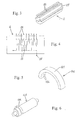
- the first and the second roller 3 are both 3-layer rollers trained and serve as sandwich rolls, between which five paper webs 1a-1e performed and to a paper strand 1 are brought together and pressed.
- the paper strand 1 then arrives at one with a transverse one Knife provided knife roller 4 and a counter roller 5, between which he divided into single sheet packages becomes.
- the single sheet packages are then by a pair of pull rollers 6 first a collecting cylinder 7 and then one Folding cylinder 8 fed and are finally folded.
- the first and the second roller 3 each have a semiconducting one outermost layer 34, an underlying highly conductive Layer 33, an underlying insulating Layer 32 and a core 31.
- the core 31 comprises one Shaft 311, via which the roller 3 in bearings 35 in the machine frame 9 is rotatably mounted.
- the bearings of the rollers 3 are not electrically isolated, which is due to the insulating Layer 32 is also not necessary.
- the core 31 is in Normally made of steel, while the semiconducting extreme Layer 34 is preferably made of rubber.
- the highly conductive Layer 33 and the insulating layer 32 consist of conventional ones conductive or insulating materials, for example Metal, rubber or synthetic resin.
- two inductor electrodes 2 which are about 1 - 50 mm apart arranged by one of the two rollers 3 are.
- the two inductor electrodes 2 are under one High voltage opposite sign set up can be up to 60 kV or -60 kV. This is what happens a current flow from the one inductor electrode 2 via the Air gap to the semiconducting outermost layer 34 and the highly conductive layer 33 of the first roller 3, and from there due to the direct contact with the paper strand 1 through this to the semiconducting extreme Layer 34 and the highly conductive layer 33 of the second roller 3.
- the highly conductive layer 33 under the semiconducting extreme Layer 34 is used to flow the whole Distribute roller width evenly, even if, as shown, Inductor electrodes 2 are used only extend over part of the roll width. thanks to the highly conductive layer 33 can also be used short electrodes whose length is only a fraction of the roll width, e.g. 1/6, is.
- the rod-shaped, elongated inductor electrode 2 shown is known per se in its structure and is used by the applicant distributed for years.
- Insulation bodies 21 are one in a row
- a protective resistor is located behind each emission needle 22 23 switched.
- the emission needles 22 and protective resistors 23 are advantageously positioned on a circuit board, which inserted into the insulation body 21 and is potted with synthetic resin, for example.
- the connection contact 24 of the inductor electrode 2 is with a High voltage source connected.
- the inductor electrodes can have different shapes.
- an inductor electrode 102 has a semicircular shape and surrounds one Roller 103 at a distance of between about 1 and 50 mm.
- the insulation body 121 of the inductor electrode 102 in which a series of emission needles 122 are arranged in an arc over 180 °.
- the inductor electrode is accessible for service work 102 preferably close to one end of roller 103 placed.
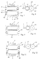
- the first roller 3 again a 3-layer roller corresponding to the first Embodiment.
- the second roller 103 is a 1-layer roller with a highly or semiconducting extreme Layer 132 around a core 131 and is in bearings 135 rotatably supported in the machine frame 9. Both rollers 3, 103, an inductor electrode 2 is assigned for charging, what due to the lack of insulating layer in the second roller 103 attaching bearing insulation 136 makes necessary.
- the current flow is similar to the first embodiment, with the simpler here second roller 103 at best a less optimal current distribution results.
- only the first Roller 3 is charged by means of an inductor electrode 2. The current flows from the first roller 3 through the paper strand 1 through to and over the second roller 103 Steel core 131 for machine earth.
- This device is relatively inexpensive because it only an inductor electrode 2 and a high voltage supply needed.
- both are rollers 103 as 1-layer rolls with a semiconducting extreme Layer 132 formed around a core 131 and in bearings 135 rotatably mounted in the machine frame 9.
- Both An inductor electrode 2 is assigned to rollers 103 for charging and the bearings 135 of both rollers 103 are with one Bearing insulation 136 provided to drain current to machine ground to prevent. The current flow is similar as in the first embodiment.
- the first and the second roller 203 as a 2-layer roller with a semiconducting outermost layer 233, an underlying layer insulating layer 232 and a core 231 and in non-electrically insulated bearings 235 in the machine frame 9 rotatably mounted.
- Both rollers 203 are for charging assigned an inductor electrode 2, the length of which is due to the lack of a highly conductive layer between the semiconducting outermost layer 233 and the insulating Layer 232 in each case approximately the roll width or the paper strand width should correspond to an optimal To achieve power distribution.
- the current flow is similar as in the first embodiment.
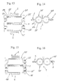
- the first roller 203 again a two-layer roller corresponding to the fifth Embodiment.
- the second roller 103 is a 1-layer roller with a highly or semiconducting extreme Layer 132 around a core 131.
- the bearings 135 of the second roller 103 are provided with bearing insulation 136, to prevent current drainage to machine ground.
- Both rollers 203, 103 have an inductor electrode for charging 2 assigned. The current flow is similar to that of first embodiment.
- the two rollers 203 and 103 constructed as in the sixth embodiment, except that the bearings 135 of the second roller 103 are not electrically isolated here.
- first roller 203 is charged by means of an inductor electrode 2. The current flows from the first roller 203 through the paper strand 1 through to the second roller 103 and over their steel core 131 to machine earth.
- This device is also relatively inexpensive since it only one inductor electrode 2 and a high voltage supply needed.
- both rollers are 3rd as 3-layer rollers according to the first embodiment built up.
- Both rollers 3 is one for charging Inductor electrode 2 assigned.
- the two rollers 3 here not the sandwich rolls bringing the paper webs together, which are not shown here, but in the direction of travel of the paper strand 1 further arranged rollers.
- the first roller 3 and the second roller 3 are also in Direction of movement of the paper strand 1 slightly offset from each other. The current flows from the first roller 3 via the paper strand 1 to the second roller 3.
- This ninth embodiment largely corresponds to that eighth embodiment. The only difference is in that the first roller 3 and the second roller 3 in Direction of travel of the paper strand 1 still further to each other are offset.
- the first roller 3 again a 3-layer roller corresponding to the ninth Embodiment.
- the second roller 303 is a steel roller, which is accordingly a highly conductive, not separate formed outermost layer 331.
- the first Roller 3 and the second roller 303 are in the direction of the Paper strand 1 offset from each other. Only the first roller 3 an inductor electrode 2 is assigned for charging. The Current flows from the first roller 3 through the paper strand 1 to the second roller 3 and from this to the machine earth.
Landscapes
- Registering, Tensioning, Guiding Webs, And Rollers Therefor (AREA)
- Electrophotography Configuration And Component (AREA)
- Folding Of Thin Sheet-Like Materials, Special Discharging Devices, And Others (AREA)
- Replacement Of Web Rolls (AREA)
Abstract
Description
- Fig. 1 -
- eine Seitenansicht eines Falzapparats mit einem ersten Ausführungsbeispiel der erfindungsgemässen Vorrichtung zum Vereinigen von mindestens zwei Papierbahnen zu einem Papierstrang mit 3-Schicht-Walzen als erster und zweiter Walze;
- Fig. 2 -
- eine Ansicht von vorne der ersten und zweiten Walze und der Induktorelektroden von Fig. 1;
- Fig. 3 -
- eine Perspektivansicht einer länglichen Induktorelektrode mit einer Reihe von Emissionsnadeln;
- Fig. 4 -
- das elektrische Schaltbild der Induktorelektrode von Fig. 3;
- Fig. 5 -
- eine Perspektivansicht einer halbbogenförmigen Induktorelektrode;
- Fig. 6 -
- die Induktorelektrode von Fig. 5 angesetzt an eine Walze;
- Fig. 7 -
- ein zweites Ausführungsbeispiel der erfindungsgemässen Vorrichtung mit einer 3-Schicht-Walze als erster Walze und einer 1-Schicht-Walze als zweiter Walze und mit zwei Induktorelektroden;
- Fig. 8 -
- eine Seitenansicht der Vorrichtung von Fig. 7;
- Fig. 9 -
- ein drittes Ausführungsbeispiel der erfindungsgemässen Vorrichtung mit einer 3-Schicht-Walze als erster Walze und einer 1-Schicht-Walze als zweiter Walze und mit nur einer Induktorelektrode;
- Fig. 10 -
- eine Seitenansicht der Vorrichtung von Fig. 9;
- Fig. 11 -
- ein viertes Ausführungsbeispiel der erfindungsgemässen Vorrichtung mit 1-Schicht-Walzen als erster und zweiter Walze;
- Fig. 12 -
- eine Seitenansicht der Vorrichtung von Fig. 11;
- Fig. 13 -
- ein fünftes Ausführungsbeispiel der erfindungsgemässen Vorrichtung mit 2-Schicht-Walzen als erster und zweiter Walze;
- Fig. 14 -
- eine Seitenansicht der Vorrichtung von Fig. 13;
- Fig. 15 -
- ein sechstes Ausführungsbeispiel der erfindungsgemässen Vorrichtung mit einer 2-Schicht-Walze als erster Walze und einer 1-Schicht-Walze als zweiter Walze und mit zwei Induktorelektroden;
- Fig. 16 -
- eine Seitenansicht der Vorrichtung von Fig. 15;
- Fig. 17 -
- ein siebtes Ausführungsbeispiel der erfindungsgemässen Vorrichtung mit einer 2-Schicht-Walze als erster Walze und einer 1-Schicht-Walze als zweiter Walze und mit nur einer Induktorelektrode;
- Fig. 18 -
- eine Seitenansicht der Vorrichtung von Fig. 17;
- Fig. 19 -
- ein achtes Ausführungsbeispiel der erfindungsgemässen Vorrichtung mit in Laufrichtung des Papierstrangs zueinander versetzten 3-Schicht-Walzen als erster und zweiter Walze;
- Fig. 20 -
- ein neuntes Ausführungsbeispiel der erfindungsgemässen Vorrichtung mit im Vergleich zum achten Ausführungsbeispiel noch weiter versetzten 3-Schicht-Walzen als erster und zweiter Walze; und
- Fig. 21 -
- ein zehntes Ausführungsbeispiel der erfindungsgemässen Vorrichtung mit einer 3-Schicht-Walze als erster Walze und einer Stahlwalze als zweiter Walze, wobei die beiden Walzen in Laufrichtung des Papierstrangs zueinander versetzt sind.
- Die Induktorelektroden können verschiedenartig aufgebaut sein und müssen nicht unbedingt Emissionsnadeln aufweisen. Denkbar sind beispielsweise auch segmentierte Elektroden mit etwa 20 mm2 grossen Emissionsflächen anstatt - nadeln oder Fadenelektroden mit einem in einem Isolationskörper montierten gespannten Draht.
- Die oben beschriebenen Ausführungsbeispiele stellen nur ausgewählte Varianten von Walzen- und Induktorelektrodenkonstruktionen und -anordnungen dar. Prinzipiell sind im Rahmen der Patentansprüche noch viele andere Konstruktionen und Kombinationen möglich.
Claims (10)
- Vorrichtung zum Vereinigen von mindestens zwei Papierbahnen (1a-1e) zu einem Papierstrang (1), mit zwei Sandwichwalzen (3, 103, 203, 303), zwischen denen die Papierbahnen (1a-1e) durchführbar und von denen diese zu einem Papierstrang (1) zusammenführbar sind, wobei die Vorrichtung ein Walzenpaar mit einer ersten und einer zweiten Walze (3, 103, 203, 303) umfasst, die jeweils eine hochleitende oder halbleitende äusserste Schicht (34, 132, 233, 331) aufweisen, und Lademittel vorhanden sind, um zumindest die äusserste Schicht (34, 132, 233, 331) der ersten Walze (3, 103, 203, 303) elektrisch aufzuladen, dadurch gekennzeichnet, dass die Lademittel eine Induktorelektrode (2; 102) umfassen, die beabstandet von der ersten Walze (3, 103, 203, 303) angeordnet ist.
- Vorrichtung nach Anspruch 1, dadurch gekennzeichnet, dass sie eine weitere Induktorelektrode (2; 102) umfasst, die beabstandet von der zweiten Walze (3, 103, 203, 303) angeordnet ist, um deren äusserste Schicht (34, 132, 233, 331) mit im Vergleich zur äussersten Schicht (34, 132, 233, 331) der ersten Walze (3, 103, 203, 303) vorzeichenmässig entgegengesetzter Ladung elektrisch aufzuladen.
- Vorrichtung nach Anspruch 1 oder 2, dadurch gekennzeichnet, dass die erste und/oder die zweite Walze (3) eine halbleitende äusserste Schicht (34), eine darunterliegende hochleitende Schicht (33), eine darunterliegende isolierende Schicht (32) und einen Kern (31) aufweisen.
- Vorrichtung nach einem der Ansprüche 1 bis 3, dadurch gekennzeichnet, dass die erste und/oder die zweite Walze (203) eine halbleitende äusserste Schicht (233), eine darunterliegende isolierende Schicht (232) und einen Kern (231) aufweisen.
- Vorrichtung nach einem der Ansprüche 1 bis 4, dadurch gekennzeichnet, dass die erste und/oder die zweite Walze (103) eine hoch- oder halbleitende äusserste Schicht (132) und einen direkt darunterliegenden Kern (131) aufweisen.
- Vorrichtung nach einem der Ansprüche 1 bis 5, dadurch gekennzeichnet, dass die zweite Walze eine Stahlwalze (303) ist und die hochleitende äusserste Schicht (331) durch die Stahlwalze (303) selbst gebildet ist.
- Vorrichtung nach einem der Ansprüche 1 bis 6, dadurch gekennzeichnet, dass die Lager (35, 135) der ersten und/oder der zweiten Walze (3, 103, 203, 303) elektrisch isoliert sind.
- Vorrichtung nach einem der Ansprüche 1 bis 7, dadurch gekennzeichnet, dass die erste und die zweite Walze (3, 103, 203, 303) die beiden Sandwichwalzen sind.
- Vorrichtung nach einem der Ansprüche 1 bis 8, dadurch gekennzeichnet, dass die erste und die zweite Walze (3, 103, 203, 303) in Laufrichtung des Papierstrangs (1) nach den beiden Sandwichwalzen so angeordnet sind, dass der Papierstrang (1) zwischen ihnen durchführbar ist und an beiden anliegt, wobei vorzugsweise die erste und die zweite Walze (3, 103, 203, 303) in Laufrichtung des Papierstrangs (1) versetzt angeordnet sind.
- Vorrichtung nach einem der Ansprüche 1 bis 9, dadurch gekennzeichnet, dass die Induktorelektrode bzw. -elektroden (2; 102) von der ersten und gegebenenfalls der zweiten Walze (3, 103, 203, 303) in einem wirksamen Abstand von zwischen 1 mm und 50 mm angeordnet ist bzw. sind und vorzugsweise die an die Induktorelektrode bzw. -elektroden (2; 102) angelegte Spannung zwischen 10 kV und 60 kV beträgt.
Applications Claiming Priority (2)
| Application Number | Priority Date | Filing Date | Title |
|---|---|---|---|
| CH9712000 | 2000-05-16 | ||
| CH9712000 | 2000-05-16 |
Publications (2)
| Publication Number | Publication Date |
|---|---|
| EP1285875A1 true EP1285875A1 (de) | 2003-02-26 |
| EP1285875B1 EP1285875B1 (de) | 2006-03-29 |
Family
ID=4550998
Family Applications (1)
| Application Number | Title | Priority Date | Filing Date |
|---|---|---|---|
| EP01810073A Revoked EP1285875B1 (de) | 2000-05-16 | 2001-01-25 | Vorrichtung zum Vereinigen von mindestens zwei Papierbahnen zu einem Papierstrang |
Country Status (4)
| Country | Link |
|---|---|
| EP (1) | EP1285875B1 (de) |
| AT (1) | ATE321720T1 (de) |
| DE (2) | DE20101202U1 (de) |
| ES (1) | ES2260185T3 (de) |
Cited By (5)
| Publication number | Priority date | Publication date | Assignee | Title |
|---|---|---|---|---|
| WO2004101407A1 (de) * | 2003-05-13 | 2004-11-25 | Windmöller & Hölscher Kg | Wickelvorrichtung mit elektrostatischen auflademitteln und verfahren zum festlegen mehrlagiger folie |
| FR2883267A1 (fr) * | 2005-03-18 | 2006-09-22 | Thibeau Soc Par Actions Simpli | Procede et systeme de transport d'une bande de non-tisse avec maintien electrostatique dans au moins une zone de dimension inferieure a la largeur de ladite bande |
| NL1029461C2 (nl) * | 2005-07-07 | 2007-01-09 | Simco Nederland | Werkwijze en inrichting voor het bijeenhouden van een elektrisch niet-geleidende stapel van voorwerpen. |
| DE102005042438A1 (de) * | 2005-09-07 | 2007-03-08 | Man Roland Druckmaschinen Ag | Vorrichtung zum Zusammenführen mehrerer Bedruckstoffbahnen |
| US8559156B2 (en) | 2008-06-03 | 2013-10-15 | Illinois Tool Works Inc. | Method and apparatus for charging or neutralizing an object using a charged piece of conductive plastic |
Citations (4)
| Publication number | Priority date | Publication date | Assignee | Title |
|---|---|---|---|---|
| DE2754179A1 (de) * | 1977-12-06 | 1979-08-23 | Maschf Augsburg Nuernberg Ag | Einer rollenrotationsdruckmaschine nachgeschaltete bearbeitungsstation |
| CH659035A5 (de) * | 1980-05-06 | 1986-12-31 | Walter Spengler | Verfahren zum zusammentragen von buendeln aus elektrisch isolierenden bogenfoermigen haelftig gefalteten substratmaterialien. |
| EP0378350A2 (de) * | 1989-01-13 | 1990-07-18 | Abisare Co., Ltd. | Verfahren zum Transportieren eines Papierbogens |
| DE19713662A1 (de) * | 1997-04-02 | 1998-10-08 | Eltex Elektrostatik Gmbh | Verfahren und Vorrichtung zum elektrostatischen Aufladen |
-
2001
- 2001-01-24 DE DE20101202U patent/DE20101202U1/de not_active Expired - Lifetime
- 2001-01-25 AT AT01810073T patent/ATE321720T1/de not_active IP Right Cessation
- 2001-01-25 EP EP01810073A patent/EP1285875B1/de not_active Revoked
- 2001-01-25 ES ES01810073T patent/ES2260185T3/es not_active Expired - Lifetime
- 2001-01-25 DE DE50109375T patent/DE50109375D1/de not_active Expired - Fee Related
Patent Citations (4)
| Publication number | Priority date | Publication date | Assignee | Title |
|---|---|---|---|---|
| DE2754179A1 (de) * | 1977-12-06 | 1979-08-23 | Maschf Augsburg Nuernberg Ag | Einer rollenrotationsdruckmaschine nachgeschaltete bearbeitungsstation |
| CH659035A5 (de) * | 1980-05-06 | 1986-12-31 | Walter Spengler | Verfahren zum zusammentragen von buendeln aus elektrisch isolierenden bogenfoermigen haelftig gefalteten substratmaterialien. |
| EP0378350A2 (de) * | 1989-01-13 | 1990-07-18 | Abisare Co., Ltd. | Verfahren zum Transportieren eines Papierbogens |
| DE19713662A1 (de) * | 1997-04-02 | 1998-10-08 | Eltex Elektrostatik Gmbh | Verfahren und Vorrichtung zum elektrostatischen Aufladen |
Cited By (9)
| Publication number | Priority date | Publication date | Assignee | Title |
|---|---|---|---|---|
| WO2004101407A1 (de) * | 2003-05-13 | 2004-11-25 | Windmöller & Hölscher Kg | Wickelvorrichtung mit elektrostatischen auflademitteln und verfahren zum festlegen mehrlagiger folie |
| FR2883267A1 (fr) * | 2005-03-18 | 2006-09-22 | Thibeau Soc Par Actions Simpli | Procede et systeme de transport d'une bande de non-tisse avec maintien electrostatique dans au moins une zone de dimension inferieure a la largeur de ladite bande |
| EP1702874A3 (de) * | 2005-03-18 | 2007-05-30 | Asselin-Thibeau | Method and device of transporting a non-woven web with electrostatic charge in at least an area with a dimension smaller than the width of said web |
| NL1029461C2 (nl) * | 2005-07-07 | 2007-01-09 | Simco Nederland | Werkwijze en inrichting voor het bijeenhouden van een elektrisch niet-geleidende stapel van voorwerpen. |
| EP1741652A1 (de) * | 2005-07-07 | 2007-01-10 | Illinois Tool Works Inc. | Verfahren und Vorrichtung zum Zusammenhalten von einem nichtleitenden Stapel von Gegenständen |
| US8242411B2 (en) * | 2005-07-07 | 2012-08-14 | Illinois Tool Works Inc. | Method and device for holding together an electronically non-conductive stack of objects |
| DE102005042438A1 (de) * | 2005-09-07 | 2007-03-08 | Man Roland Druckmaschinen Ag | Vorrichtung zum Zusammenführen mehrerer Bedruckstoffbahnen |
| US7644912B2 (en) | 2005-09-07 | 2010-01-12 | Man Roland Druckmaschinen Ag | Apparatus and method for leading together a number of printed webs |
| US8559156B2 (en) | 2008-06-03 | 2013-10-15 | Illinois Tool Works Inc. | Method and apparatus for charging or neutralizing an object using a charged piece of conductive plastic |
Also Published As
| Publication number | Publication date |
|---|---|
| ES2260185T3 (es) | 2006-11-01 |
| DE20101202U1 (de) | 2001-05-10 |
| DE50109375D1 (de) | 2006-05-18 |
| ATE321720T1 (de) | 2006-04-15 |
| EP1285875B1 (de) | 2006-03-29 |
Similar Documents
| Publication | Publication Date | Title |
|---|---|---|
| DE3018982C2 (de) | ||
| EP1072551B1 (de) | Falzapparatanordnung und Verfahren zum Falzen in einer Rollenrotationszeitungsdruckmaschine | |
| EP1106554B1 (de) | Bewegbarer Falzapparat und Falztrichteranordnung | |
| DE2120903B2 (de) | Vorrichtung zum Falten von Bahnen in mehrfach gefaltete Einzelprodukte | |
| DE10236658B4 (de) | Schnittregister-Aufteilung | |
| DE4012246C1 (de) | ||
| EP1106555A2 (de) | Einrichtung zur Führung von Materialbahnen in Rotationsdruckmaschinen | |
| EP1285875B1 (de) | Vorrichtung zum Vereinigen von mindestens zwei Papierbahnen zu einem Papierstrang | |
| EP0439822B1 (de) | Presseur einer Tiefdruckrotationsmaschine | |
| EP0971851B1 (de) | Vorrichtung zum elektrostatischen aufladen | |
| DE102019116263B4 (de) | Einrichtung mit einer Mehrfach-Strangbildungsvorrichtung und Verfahren der Tabak verarbeitenden Industrie | |
| AT518731B1 (de) | Richtmaschine | |
| DE4407405A1 (de) | Trockenpartie | |
| EP1456107A1 (de) | Vorrichtung zur herstellung von falzprodukten | |
| DE102006013955B3 (de) | Einrichtungen zum Zuführen einer Materialbahn zu einer Druckeinheit | |
| CH634529A5 (en) | Folder connected downstream of a web-fed rotary printing machine | |
| DE1220113B (de) | Vorrichtung zum kontinuierlichen Verbinden von mit einer Oberflaeche aus thermoplastischem Kunststoff versehenen Flachbahnen | |
| DE7711116U1 (de) | Filteransetzmaschine fuer die zigarettenfertigung | |
| CH670217A5 (de) | ||
| DE19942031B4 (de) | Verfahren zum Betreiben einer Rollenrotations-Druckmaschine | |
| DE19805723A1 (de) | Trockenpartie sowie Verfahren zum Betreiben einer solchen Trockenpartie | |
| EP0774351B1 (de) | Vorrichtung zum elektrostatischen Fixieren eines mehrlagigen Flachmaterials | |
| DE102006013956B4 (de) | Druckmaschine mit einer Einrichtung zum Zuführen einer Materialbahn und ein Verfahren zum Zuführen einer Materialbahn | |
| DE102006013954B4 (de) | Druckmaschine mit einer Einrichtung zum Zuführen einer Materialbahn | |
| DE10012346A1 (de) | Vorrichtung und Verfahren zum direkten oder indirekten Auftragen eines flüssigen oder pastösen Auftragsmediums auf eine laufende Materialbahn, insbesondere aus Papier oder Karton |
Legal Events
| Date | Code | Title | Description |
|---|---|---|---|
| PUAI | Public reference made under article 153(3) epc to a published international application that has entered the european phase |
Free format text: ORIGINAL CODE: 0009012 |
|
| AK | Designated contracting states |
Kind code of ref document: A1 Designated state(s): AT BE CH CY DE DK ES FI FR GB GR IE IT LI LU MC NL PT SE TR Designated state(s): AT BE CH CY DE DK ES FI FR GB GR IE IT LI LU MC NL PT SE TR |
|
| AX | Request for extension of the european patent |
Extension state: AL LT LV MK RO SI |
|
| 17P | Request for examination filed |
Effective date: 20030811 |
|
| AKX | Designation fees paid |
Designated state(s): AT BE CH CY DE DK ES FI FR GB GR IE IT LI LU MC NL PT SE TR |
|
| GRAP | Despatch of communication of intention to grant a patent |
Free format text: ORIGINAL CODE: EPIDOSNIGR1 |
|
| GRAS | Grant fee paid |
Free format text: ORIGINAL CODE: EPIDOSNIGR3 |
|
| GRAA | (expected) grant |
Free format text: ORIGINAL CODE: 0009210 |
|
| AK | Designated contracting states |
Kind code of ref document: B1 Designated state(s): AT BE CH CY DE DK ES FI FR GB GR IE IT LI LU MC NL PT SE TR |
|
| PG25 | Lapsed in a contracting state [announced via postgrant information from national office to epo] |
Ref country code: NL Free format text: LAPSE BECAUSE OF FAILURE TO SUBMIT A TRANSLATION OF THE DESCRIPTION OR TO PAY THE FEE WITHIN THE PRESCRIBED TIME-LIMIT Effective date: 20060329 Ref country code: LI Free format text: LAPSE BECAUSE OF NON-PAYMENT OF DUE FEES Effective date: 20060329 Ref country code: IT Free format text: LAPSE BECAUSE OF FAILURE TO SUBMIT A TRANSLATION OF THE DESCRIPTION OR TO PAY THE FEE WITHIN THE PRESCRIBED TIME-LIMIT;WARNING: LAPSES OF ITALIAN PATENTS WITH EFFECTIVE DATE BEFORE 2007 MAY HAVE OCCURRED AT ANY TIME BEFORE 2007. THE CORRECT EFFECTIVE DATE MAY BE DIFFERENT FROM THE ONE RECORDED. Effective date: 20060329 Ref country code: IE Free format text: LAPSE BECAUSE OF FAILURE TO SUBMIT A TRANSLATION OF THE DESCRIPTION OR TO PAY THE FEE WITHIN THE PRESCRIBED TIME-LIMIT Effective date: 20060329 Ref country code: CH Free format text: LAPSE BECAUSE OF NON-PAYMENT OF DUE FEES Effective date: 20060329 |
|
| REG | Reference to a national code |
Ref country code: GB Ref legal event code: FG4D Free format text: NOT ENGLISH |
|
| REG | Reference to a national code |
Ref country code: CH Ref legal event code: EP |
|
| REG | Reference to a national code |
Ref country code: IE Ref legal event code: FG4D Free format text: LANGUAGE OF EP DOCUMENT: GERMAN |
|
| REF | Corresponds to: |
Ref document number: 50109375 Country of ref document: DE Date of ref document: 20060518 Kind code of ref document: P |
|
| PLBI | Opposition filed |
Free format text: ORIGINAL CODE: 0009260 |
|
| PG25 | Lapsed in a contracting state [announced via postgrant information from national office to epo] |
Ref country code: SE Free format text: LAPSE BECAUSE OF FAILURE TO SUBMIT A TRANSLATION OF THE DESCRIPTION OR TO PAY THE FEE WITHIN THE PRESCRIBED TIME-LIMIT Effective date: 20060629 Ref country code: DK Free format text: LAPSE BECAUSE OF FAILURE TO SUBMIT A TRANSLATION OF THE DESCRIPTION OR TO PAY THE FEE WITHIN THE PRESCRIBED TIME-LIMIT Effective date: 20060629 |
|
| REG | Reference to a national code |
Ref country code: CH Ref legal event code: NV Representative=s name: A. BRAUN, BRAUN, HERITIER, ESCHMANN AG PATENTANWAE |
|
| 26 | Opposition filed |
Opponent name: ELTEX-ELEKTROSTATIK GESELLSCHAFT MBH Effective date: 20060523 |
|
| GBT | Gb: translation of ep patent filed (gb section 77(6)(a)/1977) |
Effective date: 20060612 |
|
| PLAZ | Examination of admissibility of opposition: despatch of communication + time limit |
Free format text: ORIGINAL CODE: EPIDOSNOPE2 |
|
| PLBA | Examination of admissibility of opposition: reply received |
Free format text: ORIGINAL CODE: EPIDOSNOPE4 |
|
| PLAB | Opposition data, opponent's data or that of the opponent's representative modified |
Free format text: ORIGINAL CODE: 0009299OPPO |
|
| R26 | Opposition filed (corrected) |
Opponent name: ELTEX ELEKTROSTATIK GMBH Effective date: 20060523 |
|
| PG25 | Lapsed in a contracting state [announced via postgrant information from national office to epo] |
Ref country code: PT Free format text: LAPSE BECAUSE OF FAILURE TO SUBMIT A TRANSLATION OF THE DESCRIPTION OR TO PAY THE FEE WITHIN THE PRESCRIBED TIME-LIMIT Effective date: 20060829 |
|
| NLR1 | Nl: opposition has been filed with the epo |
Opponent name: ELTEX-ELEKTROSTATIK GESELLSCHAFT MBH |
|
| NLV1 | Nl: lapsed or annulled due to failure to fulfill the requirements of art. 29p and 29m of the patents act | ||
| REG | Reference to a national code |
Ref country code: ES Ref legal event code: FG2A Ref document number: 2260185 Country of ref document: ES Kind code of ref document: T3 |
|
| ET | Fr: translation filed | ||
| REG | Reference to a national code |
Ref country code: IE Ref legal event code: FD4D |
|
| PLAX | Notice of opposition and request to file observation + time limit sent |
Free format text: ORIGINAL CODE: EPIDOSNOBS2 |
|
| PGFP | Annual fee paid to national office [announced via postgrant information from national office to epo] |
Ref country code: AT Payment date: 20070102 Year of fee payment: 7 |
|
| PLBI | Opposition filed |
Free format text: ORIGINAL CODE: 0009260 |
|
| PG25 | Lapsed in a contracting state [announced via postgrant information from national office to epo] |
Ref country code: MC Free format text: LAPSE BECAUSE OF NON-PAYMENT OF DUE FEES Effective date: 20070131 |
|
| PLBB | Reply of patent proprietor to notice(s) of opposition received |
Free format text: ORIGINAL CODE: EPIDOSNOBS3 |
|
| 26 | Opposition filed |
Opponent name: KOENIG & BAUER AKTIENGESELLSCHAFT -LIZENZEN-PATENT Effective date: 20061222 Opponent name: ELTEX ELEKTROSTATIK GMBH Effective date: 20060523 |
|
| RDAF | Communication despatched that patent is revoked |
Free format text: ORIGINAL CODE: EPIDOSNREV1 |
|
| RDAG | Patent revoked |
Free format text: ORIGINAL CODE: 0009271 |
|
| REG | Reference to a national code |
Ref country code: CH Ref legal event code: PL |
|
| STAA | Information on the status of an ep patent application or granted ep patent |
Free format text: STATUS: PATENT REVOKED |
|
| GBPC | Gb: european patent ceased through non-payment of renewal fee |
Effective date: 20070125 |
|
| 27W | Patent revoked |
Effective date: 20070608 |
|
| PG25 | Lapsed in a contracting state [announced via postgrant information from national office to epo] |
Ref country code: GB Free format text: LAPSE BECAUSE OF NON-PAYMENT OF DUE FEES Effective date: 20070125 |
|
| PG25 | Lapsed in a contracting state [announced via postgrant information from national office to epo] |
Ref country code: GR Free format text: LAPSE BECAUSE OF FAILURE TO SUBMIT A TRANSLATION OF THE DESCRIPTION OR TO PAY THE FEE WITHIN THE PRESCRIBED TIME-LIMIT Effective date: 20060630 |
|
| PG25 | Lapsed in a contracting state [announced via postgrant information from national office to epo] |
Ref country code: FI Free format text: LAPSE BECAUSE OF FAILURE TO SUBMIT A TRANSLATION OF THE DESCRIPTION OR TO PAY THE FEE WITHIN THE PRESCRIBED TIME-LIMIT Effective date: 20060329 |
|
| PLAB | Opposition data, opponent's data or that of the opponent's representative modified |
Free format text: ORIGINAL CODE: 0009299OPPO |