EP1286036A2 - Procédé pour influencer l'émission de substances nocives et/ou l'émission de bruit d'un moteur à combustion interne et dispositif d'injection de combustible - Google Patents
Procédé pour influencer l'émission de substances nocives et/ou l'émission de bruit d'un moteur à combustion interne et dispositif d'injection de combustible Download PDFInfo
- Publication number
- EP1286036A2 EP1286036A2 EP02016001A EP02016001A EP1286036A2 EP 1286036 A2 EP1286036 A2 EP 1286036A2 EP 02016001 A EP02016001 A EP 02016001A EP 02016001 A EP02016001 A EP 02016001A EP 1286036 A2 EP1286036 A2 EP 1286036A2
- Authority
- EP
- European Patent Office
- Prior art keywords
- fuel
- injection quantity
- injection system
- fuel injection
- plateau
- Prior art date
- Legal status (The legal status is an assumption and is not a legal conclusion. Google has not performed a legal analysis and makes no representation as to the accuracy of the status listed.)
- Granted
Links
- 238000002347 injection Methods 0.000 title claims abstract description 191
- 239000007924 injection Substances 0.000 title claims abstract description 191
- 239000000446 fuel Substances 0.000 title claims abstract description 118
- 238000000034 method Methods 0.000 title claims abstract description 39
- 238000002485 combustion reaction Methods 0.000 title claims description 25
- 239000000126 substance Substances 0.000 title 1
- 230000003044 adaptive effect Effects 0.000 claims abstract description 30
- 230000008859 change Effects 0.000 claims description 23
- 239000003344 environmental pollutant Substances 0.000 claims description 12
- 231100000719 pollutant Toxicity 0.000 claims description 12
- MWUXSHHQAYIFBG-UHFFFAOYSA-N nitrogen oxide Inorganic materials O=[N] MWUXSHHQAYIFBG-UHFFFAOYSA-N 0.000 description 12
- 239000007789 gas Substances 0.000 description 11
- 239000002245 particle Substances 0.000 description 11
- 230000004913 activation Effects 0.000 description 7
- 239000002828 fuel tank Substances 0.000 description 6
- 230000009467 reduction Effects 0.000 description 5
- 239000004071 soot Substances 0.000 description 4
- 239000000779 smoke Substances 0.000 description 3
- 230000006835 compression Effects 0.000 description 2
- 238000007906 compression Methods 0.000 description 2
- 238000010586 diagram Methods 0.000 description 2
- 230000000694 effects Effects 0.000 description 2
- 238000005516 engineering process Methods 0.000 description 2
- 230000006870 function Effects 0.000 description 2
- 238000004519 manufacturing process Methods 0.000 description 2
- 230000008569 process Effects 0.000 description 2
- 230000015572 biosynthetic process Effects 0.000 description 1
- 238000006243 chemical reaction Methods 0.000 description 1
- 230000001276 controlling effect Effects 0.000 description 1
- 238000013461 design Methods 0.000 description 1
- 239000002283 diesel fuel Substances 0.000 description 1
- 230000006872 improvement Effects 0.000 description 1
- 238000005259 measurement Methods 0.000 description 1
- 238000012986 modification Methods 0.000 description 1
- 230000004048 modification Effects 0.000 description 1
- 230000001105 regulatory effect Effects 0.000 description 1
- 239000000243 solution Substances 0.000 description 1
- 238000005507 spraying Methods 0.000 description 1
- 238000012360 testing method Methods 0.000 description 1
Images


Classifications
-
- F—MECHANICAL ENGINEERING; LIGHTING; HEATING; WEAPONS; BLASTING
- F02—COMBUSTION ENGINES; HOT-GAS OR COMBUSTION-PRODUCT ENGINE PLANTS
- F02D—CONTROLLING COMBUSTION ENGINES
- F02D41/00—Electrical control of supply of combustible mixture or its constituents
- F02D41/008—Controlling each cylinder individually
- F02D41/0087—Selective cylinder activation, i.e. partial cylinder operation
-
- F—MECHANICAL ENGINEERING; LIGHTING; HEATING; WEAPONS; BLASTING
- F02—COMBUSTION ENGINES; HOT-GAS OR COMBUSTION-PRODUCT ENGINE PLANTS
- F02D—CONTROLLING COMBUSTION ENGINES
- F02D41/00—Electrical control of supply of combustible mixture or its constituents
- F02D41/30—Controlling fuel injection
- F02D41/38—Controlling fuel injection of the high pressure type
- F02D41/3809—Common rail control systems
-
- F—MECHANICAL ENGINEERING; LIGHTING; HEATING; WEAPONS; BLASTING
- F02—COMBUSTION ENGINES; HOT-GAS OR COMBUSTION-PRODUCT ENGINE PLANTS
- F02M—SUPPLYING COMBUSTION ENGINES IN GENERAL WITH COMBUSTIBLE MIXTURES OR CONSTITUENTS THEREOF
- F02M63/00—Other fuel-injection apparatus having pertinent characteristics not provided for in groups F02M39/00 - F02M57/00 or F02M67/00; Details, component parts, or accessories of fuel-injection apparatus, not provided for in, or of interest apart from, the apparatus of groups F02M39/00 - F02M61/00 or F02M67/00; Combination of fuel pump with other devices, e.g. lubricating oil pump
- F02M63/02—Fuel-injection apparatus having several injectors fed by a common pumping element, or having several pumping elements feeding a common injector; Fuel-injection apparatus having provisions for cutting-out pumps, pumping elements, or injectors; Fuel-injection apparatus having provisions for variably interconnecting pumping elements and injectors alternatively
- F02M63/0225—Fuel-injection apparatus having a common rail feeding several injectors ; Means for varying pressure in common rails; Pumps feeding common rails
Definitions
- the present invention relates to a method for Influencing the pollutant emission values and / or the Noise levels of a fuel injection system having internal combustion engine, in particular of a diesel engine, the fuel injection system has a plurality of injectors, which are provided with appropriate control through a control device, fuel into the cylinders of the internal combustion engine. Furthermore concerns the present invention a fuel injection system for an internal combustion engine, in particular for a diesel engine, the fuel injection system having a plurality of injectors intended to with appropriate control by a control device, Fuel into the cylinders of the internal combustion engine inject.
- the Pressure generation and injection decoupled from each other are the Pressure generation and injection decoupled from each other.
- the injection pressure becomes independent of the engine speed and the injection quantity generated and is in a fuel reservoir ready for injection.
- the Injection time and the injection quantity are in one electronic control unit and calculated by an injector or an injection unit on each engine cylinder implemented via a controlled solenoid valve.
- pre-injection in which a small amount of fuel, in particular diesel fuel, is introduced into the cylinder before the so-called main injection, with which the energy for the engine's work is introduced.
- the amount of fuel introduced into the cylinder during the pre-injection can be, for example, between 1 mm 3 and 4 mm 3 .
- This pre-injection causes the combustion chamber to be preconditioned, improves the combustion efficiency and can also achieve the following effects: the compression pressure is slightly increased by a pre-reaction or partial combustion, which shortens the ignition delay of the main injection and reduces the increase in combustion pressure and the combustion pressure peaks, which leads to a so-called soft combustion.
- injection quantity control duration characteristic curves differ at least slightly in practice, even with identical injectors. This applies in particular to small injection quantities and is due to manufacturing tolerances and / or component tolerances.
- the differences in the injection quantity control duration characteristic curves can lead to the fact that specified limit values, for example particle emission limit values and noise level limit values, cannot be met, since a control that is optimal for one injector is not optimal for another injector.
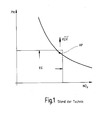
- Figure 1 shows the known relationship between the Particle emission and the emission of nitrogen oxides for a diesel engine by varying the exhaust gas recirculation rate occurs with constant start of spraying.
- This Curve shows that there is a reduction in particle emissions to an increase in nitrogen oxide emissions leads and vice versa.
- the choice of an operating point AP is therefore always a compromise, which is why the in FIG. 1 relationship also shown as a "trade-off" referred to as.
- Emission limit values EG both for particle emission as well as for the emission of nitrogen oxides it is therefore necessary to set the operating point AP in suitably on the curve shown in Figure 1 to postpone. By increasing the pre-injection quantity the trade-off is shifted according to the arrow.
- FIG. 2 shows a characteristic field known per se, which illustrates the injection quantity EM as a function of the injection period T for different pressures p s in the fuel accumulator. It can be seen from the curve profiles in FIG. 2 that the curves have a plateau P in the region of short activation times. In the area of a plateau P, the curve runs approximately parallel to the actuation duration axis, that is to say in the area of a plateau P, it is not possible to change the injection quantity by changing the actuation duration. Typically, however, the pre-injections are carried out precisely in the map region of the plateaus P.
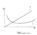
- Figure 3 shows the known relationship between Pre-injection quantity VEM and particle emission PM as well as noise G. The goal is to optimize noise or a tolerable increase in smoke.
- the assignment of the plurality of injectors according to the invention to a respective fuel injection system thereby done by the injectors after their manufacture first be divided into classes by the Course of the characteristic curves of the Depend on the injection quantity control duration characteristic.
- This Characteristic curves are possibly suitable Determine test and measurement procedures.
- the preferred on all injectors of a corresponding fuel injection system applied in the same way adaptive Measures make it possible in combination with the use predefined by injectors assigned to a class Comply with emission limit values and noise level limit values or at least improve it.
- the method provides that the at least one predetermined section of the injection quantity control duration characteristic that used for a fuel pre-injection Characteristic section includes.
- Fuel injection systems with injectors that are different Inject fuel quantities during fuel pre-injection do it in the state of the art in many Cases impossible to meet the specified limit values, because the one injected during the pre-injection Amount of fuel both based on pollutant emissions also has a strong impact on the noise level, as initially mentioned has already been explained in more detail.
- the use of Injectors, at least in this characteristic range have approximately the same properties for one Fuel injection system is therefore particularly advantageous.
- the inventive Procedures continue to be provided that the at least one predetermined section of the injection quantity control duration characteristic a plateau of the injection quantity control duration characteristic includes one Change in the control duration at least not a significant one Changes in the injection quantity causes.
- the the plateau characteristic curve section is particularly critical because within this characteristic section, as mentioned above a change in injection duration in the prior art at least no significant change in the injection quantity can be effected, which is why the use of injectors with the same or at least as possible similar plateaus for a fuel injection system is particularly advantageous.
- the at least one adaptive measure that includes the pressure in one of the fuel injection systems assigned fuel storage changed becomes. Because the fuel reservoir is preferably with everyone Connected to injectors, a change affects of the pressure in this fuel reservoir on the Injection behavior of all injectors. Since the mentioned Controller also controls the pressure in the fuel accumulator controls, the setting of this pressure, for example by suitable programming of the control device respectively.
- control respectively Control device is within the present application to be understood in such a way that it also regulates respectively Control equipment includes.
- the method according to the invention sees fuel storage preferably further before that the pressure in which the Fuel injection system assigned fuel storage is increased to reduce smoke formation, if the pre-injection volume plateau is of a relatively high Pre-injection quantity corresponds.
- the method according to the invention looks in a similar way in this regard, the pressure in which the Fuel injection system assigned fuel storage is reduced if the pre-injection quantity plateau corresponds to a relatively low pre-injection quantity.
- the inventive method can be an adaptive measure continue to provide that the at least one adaptive Measure includes changing an exhaust gas recirculation rate becomes.
- the setting of the exhaust gas recirculation rate can also through suitable programming of the motor control take place, for example, by the control device mentioned can be carried out.
- the method according to the invention further proposes that the EGR rate be reduced if the pre-injection quantity plateau of a relatively high pre-injection quantity equivalent.
- the method according to the invention looks in a similar way in this context, preferably also before that the EGR rate is increased when the pilot injection quantity plateau a relatively low pre-injection quantity equivalent.
- an adaptive measure includes a start of control the injectors are changed.
- the change in Control of the injectors can be either one Fuel pre-injection as well as a main fuel injection affect. Also the change in the start of control the injectors can be programmed appropriately the control device.
- the method according to the invention preferably further provides that the start of activation for a pre-injection is postponed early or late depending on the position of the starting point on the NO x / PM trade-off.
- the direction depends on the emission target to be achieved. If, for example, a NO x reduction is aimed for, then it is advisable to adapt the start of control late, and if soot is aimed for, it is advisable to adapt the start of control early.
- the fuel injection system according to the invention is based on the generic prior art in that to influence the pollutant emission values and / or the noise emission values of the internal combustion engine Most of the injectors in at least one predetermined Section of the injection quantity control duration characteristic has at least approximately the same characteristic curves, the control of the injectors by the control device influenced by at least one adaptive measure is that of approximately the same characteristic curves depends. In this way, the pollutant emission values and / or the noise emission values in the Be lowered compared to the prior art and it is in many cases, for example, by the legislator to comply with specified limit values.
- the at least one adaptive Measure is preferably through appropriate programming the control device realized.
- the control device control algorithms includes the at least one adaptive measure if necessary, during the service life of the internal combustion engine adapted to wear or other sizes become.
- the at least one predetermined Section of the injection quantity control duration characteristic that used for a fuel pre-injection Characteristic section includes. Similar to that The method according to the invention also applies here: fuel injection systems with injectors that are different Fuel quantities in a fuel pre-injection inject, do it in the state of the art in many Cases impossible to meet the specified limit values, because the one injected during the pre-injection Amount of fuel both based on pollutant emissions also has a strong impact on the noise level, as initially mentioned has already been explained in more detail.
- the use of Injectors, at least in this characteristic range have approximately the same properties for one Fuel injection system is therefore particularly advantageous.
- the at least one predetermined section of the injection quantity control duration characteristic a plateau of the injection quantity control duration characteristic includes a change in the control duration at least no significant change in the injection quantity causes.
- the characteristic curve section forming a plateau is particularly critical, because within this section of the characteristic curve about a change the injection duration in the prior art at least no significant change in the injection quantity can be effected. Therefore it is also related to the fuel injection systems according to the invention Use of injectors with the same or at least with similar plateaus for a fuel injection system particularly advantageous.
- Fuel storage is increased to prevent smoke from forming decrease if the pilot injection quantity plateau is one corresponds to a relatively high pre-injection quantity.
- the Fuel injection system according to the invention in this Continue to provide that the pressure in the the fuel storage system associated with the fuel injection system is reduced if the pre-injection quantity plateau corresponds to a relatively low pre-injection quantity.
- Fuel injection system should be provided that the at least one adaptive measure includes an exhaust gas recirculation rate is changed.
- a corresponding change The exhaust gas recirculation rate can also be used in this context by programming the control device accordingly respectively.
- the exhaust gas recirculation rate is reduced if the pre-injection quantity plateau corresponds to a relatively high pre-injection quantity.
- the at least one adaptive measure in addition or as an alternative to one or both of the adaptive measures explained above includes changing the start of actuation of the injectors becomes.
- a corresponding change in the start of control can be restored by programming the Control device can be achieved.
- the start of activation for a pre-injection is postponed early or late depending on the position of the starting point on the NO x / PM trade-off.
- the direction depends on the emission target to be achieved. If, for example, a NO x reduction is aimed for, then it is advisable to adapt the start of control late, and if soot is aimed for, it is advisable to adapt the start of control early.
- the invention is therefore based on the knowledge that through the use of classified injectors at least very similar characteristic curves, in particular in the range of the characteristic curve for the pre-injection is used, and performing appropriate adaptive measures, in particular through suitable Programming of the control device can be realized can, in many cases, limit values for pollutant emission values and / or the noise emission values are complied with can be.
- FIG. 4 shows the dependence of the particle emission PM and the noise level G on the pre-injection quantity VEM.
- the vertical corridor drawn around the pre-injection quantity VEM 2 is the corridor for reaching the emission target (nominal design).
- the arrow pointing from right to left illustrates a first strategy for a high pre-injection quantity, while the arrow pointing from left to right illustrates a second strategy for a low pre-injection quantity. If injectors 131 with a relatively low pre-injection quantity VEM 1 are used, it can be accepted that the actually resulting noise level is shifted into a target range TARGET, which still complies with legal requirements by carrying out at least one adaptive measure.
- the shift in the pollutant emission values and / or the noise emission values can take place in particular by reducing the pressure p s in the fuel accumulator 130 assigned to the fuel injection system 10 by increasing the exhaust gas recirculation rate a pre-injection is postponed early or late depending on the location of the starting point on the NO x / PM trade-off. The direction depends on the emission target to be achieved.
- FIG. 4 also shows an area around a normal pilot injection VEM 2 , which does not require any adaptive measures.
- the at least one adaptive measure can in particular provide that the pressure p s in a fuel accumulator assigned to the fuel injection system 10. 130 is increased, that the exhaust gas recirculation rate is reduced.
- the start of activation for a pre-injection is postponed early or late depending on the position of the starting point on the NO x / PM trade-off. The direction depends on the emission target to be achieved. If, for example, a NO x reduction is aimed for, then it is advisable to adapt the start of control late, and if soot is aimed for, it is advisable to adapt the start of control early.
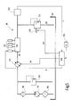
- FIG. 5 shows a block diagram of an embodiment the fuel injection system according to the invention.
- the illustrated Fuel injection system 10 is usually also called Common rail system.
- the fuel tank 100 is a fuel tank.
- the fuel tank 100 stands over a first filter 105 and one Pre-feed pump 110 with a second filter means 115 in Connection. From the second filter means 115 Fuel via a line to a high pressure pump 125.
- the connecting line between the filter means 115 and the high pressure pump 125 is above a low pressure relief valve 145 in connection with the fuel tank 100.
- the high pressure pump 125 is available with a rail or fuel accumulator 130 connected.
- the rail 130 protrudes Fuel lines with various injectors 131 in Contact.
- the rail 130 is via a pressure relief valve 135 connectable to the fuel tank 100.
- the pressure relief valve 135 can be controlled by means of a coil 136.
- the lines between the outlet of the high pressure pump 125 and the input of the pressure lock valve 135 are considered High pressure area designated. In this area is the High pressure fuel.
- the pressure in the high pressure area is detected by means of a sensor 140.
- the lines between tank 100 and high pressure pump 125 are called the low pressure range.
- a controller 160 via which the adaptive according to the invention Measures are implemented, the High pressure pump 125 with a control signal AP, the injectors 131 with a control signal A and / or that Pressure relief valve 135 with a control signal AV.
- the Controller 160 processes various signals various sensors 165, which determine the operating state of the Internal combustion engine and / or the motor vehicle that the Internal combustion engine drives, characterize. Such a The operating state is, for example, the speed N the internal combustion engine.
- the fuel, the located in the fuel tank 100 is from the Pre-feed pump 110 through filter means 105 and 115 promoted.
- the low pressure relief valve opens 145 and gives the connection between the exit of the Pre-feed pump 110 and the fuel tank 100 free.
- the high pressure pump 125 delivers the amount of fuel Q1 from Low pressure area in the high pressure area.
- the high pressure pump 125 builds a very high pressure in the Rail 130 on.
- pressure values from about 30 to 100 bar and compression ignition internal combustion engines achieved about 1000 to 2000 bar.
- the injectors 131 the fuel can be under high pressure to the individual cylinders be metered to the internal combustion engine.
- the pressure p s in the rail or in the entire high-pressure range is detected by means of the sensor 140.
- the pressure in the high pressure region is regulated by means of the controllable high pressure pump 125 and / or the pressure relief valve 135.
- Electric fuel pumps are usually used as the feed pump 110 used.
- the feed pump 110 For higher flow rates, the are particularly necessary for commercial vehicles, can also use several pre-feed pumps connected in parallel be used.
Landscapes
- Engineering & Computer Science (AREA)
- Chemical & Material Sciences (AREA)
- Combustion & Propulsion (AREA)
- Mechanical Engineering (AREA)
- General Engineering & Computer Science (AREA)
- Electrical Control Of Air Or Fuel Supplied To Internal-Combustion Engine (AREA)
- Fuel-Injection Apparatus (AREA)
- Combined Controls Of Internal Combustion Engines (AREA)
- Exhaust-Gas Circulating Devices (AREA)
- Output Control And Ontrol Of Special Type Engine (AREA)
Applications Claiming Priority (2)
| Application Number | Priority Date | Filing Date | Title |
|---|---|---|---|
| DE2001140151 DE10140151A1 (de) | 2001-08-16 | 2001-08-16 | Verfahren zur Beeinflussung der Schadstoffemissionswerte und/oder der Geräuschemissionswerte eines Verbrennungsmotors und Kraftstoff-Einspritzanlage |
| DE10140151 | 2001-08-16 |
Publications (3)
| Publication Number | Publication Date |
|---|---|
| EP1286036A2 true EP1286036A2 (fr) | 2003-02-26 |
| EP1286036A3 EP1286036A3 (fr) | 2004-06-16 |
| EP1286036B1 EP1286036B1 (fr) | 2007-01-17 |
Family
ID=7695592
Family Applications (1)
| Application Number | Title | Priority Date | Filing Date |
|---|---|---|---|
| EP20020016001 Expired - Lifetime EP1286036B1 (fr) | 2001-08-16 | 2002-07-18 | Procédé pour influencer l'émission de substances nocives et/ou l'émission de bruit d'un moteur à combustion interne et dispositif d'injection de combustible |
Country Status (3)
| Country | Link |
|---|---|
| EP (1) | EP1286036B1 (fr) |
| JP (1) | JP2003120389A (fr) |
| DE (2) | DE10140151A1 (fr) |
Cited By (2)
| Publication number | Priority date | Publication date | Assignee | Title |
|---|---|---|---|---|
| FR2896015A1 (fr) * | 2006-01-11 | 2007-07-13 | Toyota Motor Co Ltd | Systeme de commande de quantite d'injection de carburant et moteur a combustion interne comportant le systeme de commande |
| CN102606320A (zh) * | 2012-03-23 | 2012-07-25 | 潍柴动力股份有限公司 | 解决egr特性曲线变化的方法和系统 |
Families Citing this family (3)
| Publication number | Priority date | Publication date | Assignee | Title |
|---|---|---|---|---|
| DE10331241B4 (de) * | 2003-07-10 | 2014-04-30 | Robert Bosch Gmbh | Verfahren zum Injektormengenabgleich (IMA) bei Voreinspritzungen in einem Kraftstoffeinspritzsystem einer Brennkraftmaschine |
| JP4333536B2 (ja) * | 2004-09-14 | 2009-09-16 | 株式会社デンソー | ディーゼルエンジン制御システム |
| DE102008051820B4 (de) | 2008-10-15 | 2016-02-18 | Continental Automotive Gmbh | Verfahren zur Korrektur von Einspritzmengen bzw. -dauern eines Kraftstoffinjektors |
Family Cites Families (4)
| Publication number | Priority date | Publication date | Assignee | Title |
|---|---|---|---|---|
| US5634448A (en) * | 1994-05-31 | 1997-06-03 | Caterpillar Inc. | Method and structure for controlling an apparatus, such as a fuel injector, using electronic trimming |
| US5839420A (en) * | 1997-06-04 | 1998-11-24 | Detroit Diesel Corporation | System and method of compensating for injector variability |
| FR2775318B1 (fr) * | 1998-02-26 | 2000-04-28 | Sagem | Module d'injection multi-points pour moteur a combustion interne |
| JP3487207B2 (ja) * | 1999-02-01 | 2004-01-13 | 株式会社デンソー | 燃料噴射システム |
-
2001
- 2001-08-16 DE DE2001140151 patent/DE10140151A1/de not_active Withdrawn
-
2002
- 2002-07-18 DE DE50209271T patent/DE50209271D1/de not_active Expired - Fee Related
- 2002-07-18 EP EP20020016001 patent/EP1286036B1/fr not_active Expired - Lifetime
- 2002-08-14 JP JP2002236554A patent/JP2003120389A/ja active Pending
Cited By (3)
| Publication number | Priority date | Publication date | Assignee | Title |
|---|---|---|---|---|
| FR2896015A1 (fr) * | 2006-01-11 | 2007-07-13 | Toyota Motor Co Ltd | Systeme de commande de quantite d'injection de carburant et moteur a combustion interne comportant le systeme de commande |
| CN102606320A (zh) * | 2012-03-23 | 2012-07-25 | 潍柴动力股份有限公司 | 解决egr特性曲线变化的方法和系统 |
| CN102606320B (zh) * | 2012-03-23 | 2014-05-28 | 潍柴动力股份有限公司 | 解决egr特性曲线变化的方法和系统 |
Also Published As
| Publication number | Publication date |
|---|---|
| JP2003120389A (ja) | 2003-04-23 |
| EP1286036B1 (fr) | 2007-01-17 |
| DE10140151A1 (de) | 2003-02-27 |
| DE50209271D1 (de) | 2007-03-08 |
| EP1286036A3 (fr) | 2004-06-16 |
Similar Documents
| Publication | Publication Date | Title |
|---|---|---|
| DE60103785T2 (de) | Kraftstoffeinspritzungssteuergerät | |
| DE102010016093A1 (de) | Kraftstoffeinspritzerfassungsvorrichtung | |
| DE102010017123B4 (de) | Kraftstoffeinspritzsteuervorrichtung für Verbrennungsmotoren | |
| EP0793776A1 (fr) | Procede et dispositif de commande d'un moteur a combustion interne | |
| DE102007013119A1 (de) | Einspritzverfahren und zugehörige Verbrennungskraftmaschine | |
| DE19632650C1 (de) | Verfahren zum Unterdrücken von Drehmomentsprüngen beim Betrieb einer Brennkraftmaschine | |
| WO2009010374A1 (fr) | Procédé et dispositif pour mettre en forme un signal de commande électrique pour une impulsion d'injection | |
| EP1149239B1 (fr) | Systeme d'alimentation en carburant pour un moteur a combustion interne notamment d'un vehicule automobile | |
| DE102013212330A1 (de) | Verfahren zum Herstellen von Injektoren, insbesondere Kraftstoffinjektoren, sowie Injektor | |
| EP0953103A1 (fr) | Procede de demarrage d'un moteur a combustion interne | |
| DE60005617T2 (de) | Kraftstoffeinspritzsteuerungsvorrichtung für eine Brennkraftmaschine | |
| EP1090221A1 (fr) | Procede de fonctionnement d'un moteur a combustion interne, notamment pour un vehicule automobile | |
| EP1432901B1 (fr) | Procede, programme informatique et appareil de commande et/ou de regulation permettant de faire fonctionner un moteur a combustion interne, et moteur a combustion interne y relatif | |
| DE102011056159A1 (de) | Brennstoffeinspritzsteuerung für eine Verbrennungskraftmaschine | |
| EP1286036B1 (fr) | Procédé pour influencer l'émission de substances nocives et/ou l'émission de bruit d'un moteur à combustion interne et dispositif d'injection de combustible | |
| DE102004053418B4 (de) | Verfahren und Vorrichtung zur druckwellenkompensierenden Steuerung zeitlich aufeinanderfolgender Einspritzungen in einem Einspritzsystem einer Brennkraftmaschine | |
| EP1132606A2 (fr) | Procédé de commande de moteur à combustion interne | |
| DE102011051049A1 (de) | Kraftstoffeinspritzungszustandserfassungsvorrichtung | |
| DE19753072C2 (de) | Kraftstoffversorgungssystem für eine Brennkraftmaschine insbesondere eines Kraftfahrzeugs | |
| DE19917711C2 (de) | Verfahren und Vorrichtung zur Steuerung einer Brennkraftmaschine | |
| EP1278949B1 (fr) | Procede d'utilisation d'un systeme d'alimentation de carburant destine a un moteur a combustion interne d'un vehicule en particulier | |
| DE102005018221A1 (de) | Brennkraftmaschine mit Abgasrückführung | |
| DE10140093A1 (de) | Verfahren und Vorrichtung zum Ansteuern eines Magnetventils | |
| DE102006001368B4 (de) | Verfahren und Vorrichtung zur Steuerung einer Brennkraftmaschine | |
| DE10026273C2 (de) | Verfahren zur Zylindergleichstellung bei einer Verbrennungskraftmaschine |
Legal Events
| Date | Code | Title | Description |
|---|---|---|---|
| PUAI | Public reference made under article 153(3) epc to a published international application that has entered the european phase |
Free format text: ORIGINAL CODE: 0009012 |
|
| AK | Designated contracting states |
Kind code of ref document: A2 Designated state(s): AT BE BG CH CY CZ DE DK EE ES FI FR GB GR IE IT LI LU MC NL PT SE SK TR |
|
| AX | Request for extension of the european patent |
Extension state: AL LT LV MK RO SI |
|
| PUAL | Search report despatched |
Free format text: ORIGINAL CODE: 0009013 |
|
| AK | Designated contracting states |
Kind code of ref document: A3 Designated state(s): AT BE BG CH CY CZ DE DK EE ES FI FR GB GR IE IT LI LU MC NL PT SE SK TR |
|
| AX | Request for extension of the european patent |
Extension state: AL LT LV MK RO SI |
|
| RIC1 | Information provided on ipc code assigned before grant |
Ipc: 7F 02D 41/24 A Ipc: 7F 02M 65/00 B Ipc: 7F 02D 41/38 B |
|
| 17P | Request for examination filed |
Effective date: 20041216 |
|
| AKX | Designation fees paid |
Designated state(s): DE FR GB |
|
| GRAP | Despatch of communication of intention to grant a patent |
Free format text: ORIGINAL CODE: EPIDOSNIGR1 |
|
| GRAS | Grant fee paid |
Free format text: ORIGINAL CODE: EPIDOSNIGR3 |
|
| GRAA | (expected) grant |
Free format text: ORIGINAL CODE: 0009210 |
|
| AK | Designated contracting states |
Kind code of ref document: B1 Designated state(s): DE FR GB |
|
| REG | Reference to a national code |
Ref country code: GB Ref legal event code: FG4D Free format text: NOT ENGLISH |
|
| REF | Corresponds to: |
Ref document number: 50209271 Country of ref document: DE Date of ref document: 20070308 Kind code of ref document: P |
|
| GBT | Gb: translation of ep patent filed (gb section 77(6)(a)/1977) |
Effective date: 20070417 |
|
| ET | Fr: translation filed | ||
| PLBE | No opposition filed within time limit |
Free format text: ORIGINAL CODE: 0009261 |
|
| STAA | Information on the status of an ep patent application or granted ep patent |
Free format text: STATUS: NO OPPOSITION FILED WITHIN TIME LIMIT |
|
| 26N | No opposition filed |
Effective date: 20071018 |
|
| PGFP | Annual fee paid to national office [announced via postgrant information from national office to epo] |
Ref country code: FR Payment date: 20080718 Year of fee payment: 7 |
|
| PGFP | Annual fee paid to national office [announced via postgrant information from national office to epo] |
Ref country code: GB Payment date: 20080723 Year of fee payment: 7 |
|
| PGFP | Annual fee paid to national office [announced via postgrant information from national office to epo] |
Ref country code: DE Payment date: 20080925 Year of fee payment: 7 |
|
| GBPC | Gb: european patent ceased through non-payment of renewal fee |
Effective date: 20090718 |
|
| REG | Reference to a national code |
Ref country code: FR Ref legal event code: ST Effective date: 20100331 |
|
| PG25 | Lapsed in a contracting state [announced via postgrant information from national office to epo] |
Ref country code: FR Free format text: LAPSE BECAUSE OF NON-PAYMENT OF DUE FEES Effective date: 20090731 |
|
| PG25 | Lapsed in a contracting state [announced via postgrant information from national office to epo] |
Ref country code: GB Free format text: LAPSE BECAUSE OF NON-PAYMENT OF DUE FEES Effective date: 20090718 |
|
| PG25 | Lapsed in a contracting state [announced via postgrant information from national office to epo] |
Ref country code: DE Free format text: LAPSE BECAUSE OF NON-PAYMENT OF DUE FEES Effective date: 20100202 |