EP1286085B1 - Anordnung zum Umwandeln einer hin- und hergehenden Bewegung in eine schwingende Bewegung - Google Patents
Anordnung zum Umwandeln einer hin- und hergehenden Bewegung in eine schwingende Bewegung Download PDFInfo
- Publication number
- EP1286085B1 EP1286085B1 EP02292024A EP02292024A EP1286085B1 EP 1286085 B1 EP1286085 B1 EP 1286085B1 EP 02292024 A EP02292024 A EP 02292024A EP 02292024 A EP02292024 A EP 02292024A EP 1286085 B1 EP1286085 B1 EP 1286085B1
- Authority
- EP
- European Patent Office
- Prior art keywords
- connecting member
- driving device
- rotation
- ferrule
- cable
- Prior art date
- Legal status (The legal status is an assumption and is not a legal conclusion. Google has not performed a legal analysis and makes no representation as to the accuracy of the status listed.)
- Expired - Lifetime
Links
- 239000000463 material Substances 0.000 claims abstract description 16
- 229910000639 Spring steel Inorganic materials 0.000 claims description 4
- 238000002788 crimping Methods 0.000 claims description 4
- 238000003466 welding Methods 0.000 claims description 4
- 239000004033 plastic Substances 0.000 claims description 3
- 229920003023 plastic Polymers 0.000 claims description 3
- OKTJSMMVPCPJKN-UHFFFAOYSA-N Carbon Chemical compound [C] OKTJSMMVPCPJKN-UHFFFAOYSA-N 0.000 claims 1
- 229910052799 carbon Inorganic materials 0.000 claims 1
- 239000000835 fiber Substances 0.000 claims 1
- 230000010355 oscillation Effects 0.000 abstract 1
- 239000002184 metal Substances 0.000 description 3
- 229920000049 Carbon (fiber) Polymers 0.000 description 2
- 239000004917 carbon fiber Substances 0.000 description 2
- 210000000056 organ Anatomy 0.000 description 2
- 241000251556 Chordata Species 0.000 description 1
- 240000008042 Zea mays Species 0.000 description 1
- 230000008602 contraction Effects 0.000 description 1
- 238000009434 installation Methods 0.000 description 1
- 230000001131 transforming effect Effects 0.000 description 1
Images


Classifications
-
- G—PHYSICS
- G05—CONTROLLING; REGULATING
- G05G—CONTROL DEVICES OR SYSTEMS INSOFAR AS CHARACTERISED BY MECHANICAL FEATURES ONLY
- G05G7/00—Manually-actuated control mechanisms provided with one single controlling member co-operating with one single controlled member; Details thereof
- G05G7/02—Manually-actuated control mechanisms provided with one single controlling member co-operating with one single controlled member; Details thereof characterised by special provisions for conveying or converting motion, or for acting at a distance
-
- F—MECHANICAL ENGINEERING; LIGHTING; HEATING; WEAPONS; BLASTING
- F16—ENGINEERING ELEMENTS AND UNITS; GENERAL MEASURES FOR PRODUCING AND MAINTAINING EFFECTIVE FUNCTIONING OF MACHINES OR INSTALLATIONS; THERMAL INSULATION IN GENERAL
- F16H—GEARING
- F16H25/00—Gearings comprising primarily only cams, cam-followers and screw-and-nut mechanisms
- F16H25/18—Gearings comprising primarily only cams, cam-followers and screw-and-nut mechanisms for conveying or interconverting oscillating or reciprocating motions
- F16H25/20—Screw mechanisms
- F16H25/24—Elements essential to such mechanisms, e.g. screws, nuts
- F16H25/2427—Elements essential to such mechanisms, e.g. screws, nuts one of the threads being replaced by a wire or stripmetal, e.g. spring
-
- Y—GENERAL TAGGING OF NEW TECHNOLOGICAL DEVELOPMENTS; GENERAL TAGGING OF CROSS-SECTIONAL TECHNOLOGIES SPANNING OVER SEVERAL SECTIONS OF THE IPC; TECHNICAL SUBJECTS COVERED BY FORMER USPC CROSS-REFERENCE ART COLLECTIONS [XRACs] AND DIGESTS
- Y10—TECHNICAL SUBJECTS COVERED BY FORMER USPC
- Y10T—TECHNICAL SUBJECTS COVERED BY FORMER US CLASSIFICATION
- Y10T74/00—Machine element or mechanism
- Y10T74/18—Mechanical movements
- Y10T74/18568—Reciprocating or oscillating to or from alternating rotary
Definitions
- the present invention relates to devices for rotating systems movable about an axis of rotation, from the translational movement of the output member a linear actuator.
- a linear actuator 10 When it is desired to orient a device of reduced weight and bulk according to directions included in a reduced angular extent, it is common to use, as has shown in Figure 1, a linear actuator 10 whose output rod 12 is likely to be moved according to a translation movement.
- the linear actuator 10 is fixed on a frame (not shown) on which is pivotable, via an axis 14, the device whose rotational movements are desired to be controlled.
- the mobile device in rotation comprises an operating member 16 cooperating with a connecting member 18 connected to the linear motion control member constituted by the output rod 12.
- the connecting member 18 is integral with the output rod 12 of the actuator 10.
- the cooperation between the operating member 16 and the connecting member 18 is provided by a pin 20 secured to the connecting member 18 and slidably received in a slot 22 formed in the operating member 16. To avoid any risk of blockage, and to facilitate control, a certain clearance is provided between the pin 20 and the edges of the slot 22.
- the rotation angle of the mobile device in rotation is not proportional to the distance traveled by the output rod 12 of the actuator 10. indeed, simple considerations show that it is the tangent of this angle that is proportional at the run of the exit rod. As a result, the control of the movement of the actuator output rod must be performed accordingly, which complicates the law and the control circuit.
- Document US-A-3 864 983 discloses a device for transforming a rotation movement in a translation movement and vice versa, in which the element between these two movements consists of a plurality of cells series.
- Each cell consists of a pair of rotating separators, which can be adjacent to two cells.
- the separators are connected by flexible connecting elements, such that a rotation printed at one of the separators results in a contraction or an elongation of the cell.
- the present invention is placed in this context and its purpose is to propose a device for rotating a mobile system about an axis of rotation from of the translational movement of the output member of a linear actuator which does not show positioning game, in which the rotation angle of the rotating mobile system is proportional to the stroke of the output member of the actuator, such a drive device must be reliable, easy to install and inexpensive.
- the subject of the present invention is therefore a device for driving in rotation a rotating system movable about an axis under the action of the translational movement of an organ control element capable of being driven by a linear movement, the rotary system being integral with an operating member cooperating with a connecting member connected to the body of linear motion control,
- the connecting member comprises a first end rigidly secured to the operating member of the rotary system, and a second end rigidly secured to the linear motion control member.
- FIGS. 3 and 4 show a schematic view of a device rotary drive made according to the present invention.
- a device uses, as in the prior art, a linear actuator 10, the output shaft 12 is likely to be moved according to a translation movement.
- the linear actuator 10 is fixed on a frame (no shown) on which is pivotable, via an axis 14, the device which one wishes to control the movements of rotation.
- the rotating mobile device comprises there also an operating member 16 by which it is possible to control its position angular of a mobile device in rotation about the axis 14.
- a connecting member 30 is provided between the body 16 and the control member 12, this connecting member being made of a material flexible having a predetermined length L.
- a material flexible having a predetermined length L can be constituted by example by a wire rope formed of several strands spirally wound in the manner of a towing cable, by a spring steel blade, by a piano wire, and in general by any flexible material but having a high buckling resistance for a length L of this material.
- Materials that meet these conditions also include plastics, and rods formed of carbon fibers as well as springs with contiguous turns.
- connection member 30 is secured to both the operating member 16 and the body 12.
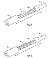
- a connection member 30, formed of a cable is shown in FIG. metal 32 having a plurality of spirally wound strands for use as a connecting member according to the present invention.
- This Figure shows that the cable 32 is integral with each of its ends of a tip 34 and 36, these ends 34 and 36 being in turn fixed rigidly on the operating member 16 and on the output rod 12.
- the cable 32 can be secured at the ends 34 and 36 by crimping, welding, overmolding, etc. In the case of a blade in spring steel, the ends of this blade can be screwed or welded onto the body of maneuver 16 and on the control member 12.
- FIG. 6 shows another connecting member 30 made of a material flexible, but having a high buckling resistance for any length L of this material.
- This is in this case a member consisting of a coil spring 38 contiguous.
- the section the wire used to form this spring will advantageously square.
- the spring 38 is secured to each end of a tip 34 and 36, these end pieces 34 and 36 being in turn fixed rigidly on the actuating member 16 and on the output shaft 12.
- the spring 38 can be secured to the ends 34 and 36 by crimping, welding, overmolding, etc.
- FIG. 3 shows a view of the training device when the rod of output 12 of the actuator 10 occupies an extreme position in which it is paid to maximum in the body of the actuator 10.
- the implementation of the actuator 10 on the frame bearing the axis 14 is such that, in this position, the axis of the output shaft 12 of the actuator passes through the point 32 for fixing the connecting member 30 to the actuating member 16. It As a result, in this so-called rest position, the connecting member 30 is rectilinear and located entirely in the extension of the output rod 12
- the actuator 10 When the actuator 10 is controlled so that the output rod 12 leaves the body of the actuator, the latter exerts a thrust on the connecting member 30, which in turn pushes on the operating member 16, and the assembly adopts a position such that the one shown in Figure 4. Indeed, one of the ends of the connecting member 30 being integral with the push rod 12, it remains in the extension thereof during the movement of the output rod 12. Similarly, the other end of the connecting member 30 being secured to the actuating member 16, it remains perpendicular thereto during the movement on the other hand, the middle part of the connecting member being flexible, and not subject to any constraint, is free to deform to transmit the movement from the output rod 12 to the operating member 16.
- the actuator adopts a shape very similar to that an arc centered at the point C of meeting lines passing through the fixing points of the connecting member 30 on the output rod 12 and on the actuating member 16.
- the result is that, the length L of the connecting member 30 being constant since it resists buckling, the operating member 16, and therefore the device movable in rotation about the integral shaft 14 of the operating member 16 rotates at an angle a proportional to the stroke of the output rod 12.
- a stop may be provided to limit the maximum this phenomenon. This is shown in Figures 7 to 9.
- one of the end pieces 34 or 36 comprises at least one, two or in the example shown, extension 40, extending parallel to the flexible element of the connecting member 30, when the latter is in the rest position, to the vicinity of a range 42 formed on the other end 36 or 34 respectively.
Landscapes
- Engineering & Computer Science (AREA)
- General Engineering & Computer Science (AREA)
- Physics & Mathematics (AREA)
- General Physics & Mathematics (AREA)
- Automation & Control Theory (AREA)
- Mechanical Engineering (AREA)
- Transmission Devices (AREA)
- Toys (AREA)
- Pinball Game Machines (AREA)
- Eye Examination Apparatus (AREA)
- Auxiliary Devices For And Details Of Packaging Control (AREA)
- Manipulator (AREA)
- Flexible Shafts (AREA)
Claims (10)
- Drehantriebsvorrichtung eines rotierenden Systems, das unter der Einwirkung einer Translationsbewegung eines durch eine lineare Bewegung bewegbaren Steuerorgans (12) um eine Achse (14) beweglich ist, wobei das rotierende System mit einem Betätigungsorgan (16) fest verbunden ist, das mit einem Verbindungsorgan (30) zusammenwirkt, welches mit dem Linearbewegungs-Steuerorgan (12) verbunden ist, wobei das Verbindungsorgan (30) eine vorbestimmte und konstante Länge (L) hat,
dadurch gekennzeichnet, dass das Verbindungsorgan (30) ein erstes Ende, das mit dem Betätigungsorgan (16) des rotierenden Systems starr verbunden ist, und ein zweites Ende aufweist, das mit dem Linearbewegungs-Steuerorgan (12) starr verbunden ist. - Antriebsvorrichtung nach Anspruch 1,
dadurch gekennzeichnet, dass das Verbindungsorgan (30) aus einem elastischen Material gebildet ist und für eine vorbestimmte Länge (L) dieses Materials eine hohe Knickfestigkeit aufweist. - Antriebsvorrichtung nach Anspruch 2,
dadurch gekennzeichnet, dass das Verbindungsorgan (30) aus einem Kabel (32) gebildet ist, das aus spiralförmig gewickelten Metalllitzen geformt ist. - Antriebsvorrichtung nach Anspruch 2,
dadurch gekennzeichnet, dass das Verbindungsorgan (30) aus einer Feder (38) mit nebeneinander liegenden Windungen gebildet ist. - Antriebsvorrichtung nach Anspruch 2,
dadurch gekennzeichnet, dass das Verbindungsorgan (30) aus einer Drahtsaite gebildet ist. - Antriebsvorrichtung nach Anspruch 2,
dadurch gekennzeichnet, dass das Verbindungsorgan (30) aus einem Metallstreifen aus Federstahl gebildet ist. - Antriebsvorrichtung nach Anspruch 2,
dadurch gekennzeichnet, dass das Verbindungsorgan (30) aus einem Kunststoff oder einer Kohlenstofffaserstange gebildet ist. - Antriebsvorrichtung nach einem der Ansprüche 3 bis 7,
dadurch gekennzeichnet, dass ein Ansatzstück (34, 36) mit wenigstens einem Ende des Kabels (32) fest verbunden ist, wobei das Ansatzstück (34, 36) starr auf dem Betätigungsorgan (16) oder dem Steuerorgan (12) befestigt ist. - Antriebsvorrichtung nach Anspruch 8,
dadurch gekennzeichnet, dass das Ansatzstück (34, 36) durch Crimpen, Schweißen oder Umspritzen fest mit dem Kabel (32) verbunden ist. - Antriebsvorrichtung nach einem der vorhergehenden Ansprüche,
dadurch gekennzeichnet, dass eines der Ansatzstücke (34, 36) wenigstens eine Verlängerung (40) aufweist, die mit einer auf dem anderen Ansatzstück ausgebildeten Auflagefläche (42) zusammenzuwirken vermag, falls eine übermäßige Beanspruchung das Knicken des elastischen Materials bewirkt.
Applications Claiming Priority (2)
| Application Number | Priority Date | Filing Date | Title |
|---|---|---|---|
| FR0111148 | 2001-08-23 | ||
| FR0111148A FR2828919B1 (fr) | 2001-08-23 | 2001-08-23 | Dispositif de transformation d'un mouvement de translation en mouvement de rotation |
Publications (2)
| Publication Number | Publication Date |
|---|---|
| EP1286085A1 EP1286085A1 (de) | 2003-02-26 |
| EP1286085B1 true EP1286085B1 (de) | 2004-09-22 |
Family
ID=8866760
Family Applications (1)
| Application Number | Title | Priority Date | Filing Date |
|---|---|---|---|
| EP02292024A Expired - Lifetime EP1286085B1 (de) | 2001-08-23 | 2002-08-08 | Anordnung zum Umwandeln einer hin- und hergehenden Bewegung in eine schwingende Bewegung |
Country Status (7)
| Country | Link |
|---|---|
| US (1) | US20030037628A1 (de) |
| EP (1) | EP1286085B1 (de) |
| JP (1) | JP2003130167A (de) |
| AT (1) | ATE277308T1 (de) |
| DE (1) | DE60201309T2 (de) |
| ES (1) | ES2229066T3 (de) |
| FR (1) | FR2828919B1 (de) |
Families Citing this family (4)
| Publication number | Priority date | Publication date | Assignee | Title |
|---|---|---|---|---|
| CN101528539B (zh) * | 2007-08-08 | 2012-06-13 | 莫戈公司 | 适用于电传飞行控制系统的控制杆 |
| JP5024960B2 (ja) * | 2008-05-30 | 2012-09-12 | 学校法人千葉工業大学 | 往復揺動機構およびこれを用いた羽ばたき飛行機 |
| ES2412486B1 (es) * | 2011-10-28 | 2014-05-09 | Antonio GUZMÁN PORRAS | Dispositivo cinemático y generador de energía que lo comprende |
| JP2019171909A (ja) * | 2018-03-27 | 2019-10-10 | Ntn株式会社 | 転舵機能付ハブユニットおよびこれを備えた車両 |
Citations (1)
| Publication number | Priority date | Publication date | Assignee | Title |
|---|---|---|---|---|
| US3864983A (en) * | 1972-09-15 | 1975-02-11 | Stephen C Jacobsen | Rotary-to-linear and linear-to-rotary motion converters |
Family Cites Families (23)
| Publication number | Priority date | Publication date | Assignee | Title |
|---|---|---|---|---|
| US1313764A (en) * | 1919-08-19 | Flexible pitman | ||
| US1291743A (en) * | 1918-06-17 | 1919-01-21 | Bissell Carpet Sweeper Co | Pitman. |
| US1915198A (en) * | 1930-05-02 | 1933-06-20 | Mark Frederick Higgins | Shaker conveyer |
| US2240087A (en) * | 1940-01-10 | 1941-04-29 | Barrett Engineering Company | Drive mechanism |
| US3515034A (en) * | 1968-10-03 | 1970-06-02 | Phillip R Eklund | Cryogenic refrigerator compressor improvement |
| CH560856A5 (de) * | 1973-02-09 | 1975-04-15 | Moser Fernand | |
| CS157455B1 (de) * | 1973-02-12 | 1974-09-16 | ||
| US3905403A (en) * | 1973-12-26 | 1975-09-16 | Kuhlman Corp | Methods of manufacturing dual interlocked safety spring assemblies |
| US3890848A (en) * | 1974-05-13 | 1975-06-24 | James G Clontz | Control assembly for rear view mirror |
| GB1526815A (en) * | 1974-11-26 | 1978-10-04 | Messerschmitt Boelkow Blohm | Stress-reducing connecting assembly |
| IT1116285B (it) * | 1977-03-09 | 1986-02-10 | Roltra Spa | Procedimento per la realizzazione di un organo di trasmissione flessibile ed organo di trasmissione flessibile ottenuto con il procedimento |
| DE2809368C2 (de) * | 1978-03-04 | 1984-02-23 | Rockwell Golde Gmbh, 6000 Frankfurt | Kabel für Fernbetätigungsvorrichtungen, insbesondere Kraftfahrzeugfensterheber |
| US4521993A (en) * | 1983-08-08 | 1985-06-11 | Truth Incorporated | Chain operator for a window |
| KR890001824B1 (ko) * | 1985-06-03 | 1989-05-25 | 요시가이기까이긴조꾸 가부시끼가이샤 | 브레이크 조작장치 |
| US4735106A (en) * | 1986-03-07 | 1988-04-05 | Yoshigai Kikai Kinzoku Co., Ltd. | Brake operating device for bicycles |
| DE3841460A1 (de) * | 1988-12-09 | 1990-06-13 | Willibald Neudert | Vorrichtung zur uebertragung von mechanischen kraeften in laengsrichtung mittels einer biegsamen stahldrahtspiralwelle |
| US5092727A (en) * | 1988-12-16 | 1992-03-03 | The B. F. Goodrich Company | Braided composite threaded member |
| US5245887A (en) * | 1989-08-30 | 1993-09-21 | Nippon Cable System Inc. | Control cable |
| JPH0726674B2 (ja) * | 1990-06-14 | 1995-03-29 | 日本スカイロボット株式会社 | フレキシブルねじ |
| US5295645A (en) * | 1992-04-13 | 1994-03-22 | Rozmus Walter J | Aircraft variable geometry nozzle |
| DE4241521A1 (de) * | 1992-12-10 | 1994-06-16 | Fichtel & Sachs Ag | Hydraulische Betätigungseinrichtung für Bremsen und Schaltungen an Fahrrädern oder dergleichen |
| US5911701A (en) * | 1998-01-29 | 1999-06-15 | Sdgi Holidings, Inc. | Surgical cutting instrument |
| US6341673B1 (en) * | 2000-04-07 | 2002-01-29 | Kuo Yung-Pin | Actuator for a hydraulic brake system of bicycles |
-
2001
- 2001-08-23 FR FR0111148A patent/FR2828919B1/fr not_active Expired - Fee Related
-
2002
- 2002-08-08 AT AT02292024T patent/ATE277308T1/de not_active IP Right Cessation
- 2002-08-08 ES ES02292024T patent/ES2229066T3/es not_active Expired - Lifetime
- 2002-08-08 EP EP02292024A patent/EP1286085B1/de not_active Expired - Lifetime
- 2002-08-08 DE DE60201309T patent/DE60201309T2/de not_active Expired - Lifetime
- 2002-08-23 JP JP2002243156A patent/JP2003130167A/ja active Pending
- 2002-08-23 US US10/226,908 patent/US20030037628A1/en not_active Abandoned
Patent Citations (1)
| Publication number | Priority date | Publication date | Assignee | Title |
|---|---|---|---|---|
| US3864983A (en) * | 1972-09-15 | 1975-02-11 | Stephen C Jacobsen | Rotary-to-linear and linear-to-rotary motion converters |
Also Published As
| Publication number | Publication date |
|---|---|
| FR2828919B1 (fr) | 2003-12-12 |
| ATE277308T1 (de) | 2004-10-15 |
| JP2003130167A (ja) | 2003-05-08 |
| ES2229066T3 (es) | 2005-04-16 |
| FR2828919A1 (fr) | 2003-02-28 |
| US20030037628A1 (en) | 2003-02-27 |
| DE60201309T2 (de) | 2006-02-23 |
| EP1286085A1 (de) | 2003-02-26 |
| DE60201309D1 (de) | 2004-10-28 |
Similar Documents
| Publication | Publication Date | Title |
|---|---|---|
| EP2503641B1 (de) | Betätigungssystem für Antennenreflektor mit einer deformierbaren reflektierenden Fläche | |
| EP2855103B1 (de) | Exoskelett stellgliedarm | |
| EP2981739A1 (de) | Kabelantrieb für erhöhten spielraum einer verbindung | |
| EP1048890B1 (de) | Flexibler Drehwinkelbegrenzungsanschlag, Gelenksystem mit solch einem Anschlag und medizinische Ausrüstung mit solch einem Gelenksystem | |
| EP0884505B1 (de) | Vorrichtung mit einem drehbaren Hebel zur Bewegungsübertragung und Ventil mit einer solchen Vorrichtung | |
| EP3222456B1 (de) | Vorrichtung zur erzeugung einer kraft | |
| EP0465280B1 (de) | Drehkupplungsvorrichtung mit hoher Präzision und damit ausgerüstete translatorisch bewegte Steuervorrichtung, insbesondere für ein optisches Instrument in einem Raumfahrzeug | |
| EP1286085A1 (de) | Anordnung zum Umwandeln einer hin- und hergehenden Bewegung in eine schwingende Bewegung | |
| WO2015135747A2 (fr) | Verin a cable equipe d'un dispositif d'anti-rotation a element longiligne flexible mais rigide en torsion | |
| FR2693568A1 (fr) | Dispositif de sécurité pour ouvrants électriques de véhicule, notamment lève-vitre et toits ouvrants, et ouvrant incorporant ce dispositif. | |
| EP2054200B1 (de) | Werkzeug mit hilfsvorrichtung zur betätigung | |
| EP0457683B1 (de) | Haspel mit gefangenem Kabel und ihre Anwendung in einem Entfaltungsregler von einem Ansatzteil eines Raumflugkörpers | |
| EP3593010B1 (de) | Führungsvorrichtung mit flexibler ermüdungsbeständigkeit gegen pseudo-parallelogramme | |
| EP3676062B1 (de) | Mechanische vorrichtung mit passiver nachgiebigkeit zur übertragung einer drehbewegung | |
| WO2013087790A1 (fr) | Ensemble mecanique articule et main mecanique comportant un tel ensemble | |
| EP2439163A1 (de) | Spannvorrichtung für Geschwindigkeitsbegrenzer mit Fallschirmauslösung für einen Aufzug | |
| FR3079438A1 (fr) | Dispositif a cables pour l’application d’efforts egaux en au moins deux points ecartes l’un de l’autre | |
| EP1864091B1 (de) | Anzeigeeinrichtung mit einem schwenkzeiger | |
| WO2014079877A1 (fr) | Dispositif de commande a ressort pour un disjoncteur | |
| EP0736882A1 (de) | Steuervorrichtung mit Elektromagnet mit Kern ohne Reibung und Verwendung bei Ventilen mit Kontinusteuerung | |
| EP1517118B1 (de) | Betätigungsorgan | |
| WO2025153415A1 (fr) | Préhenseur robotique destiné à coopérer avec un dispositif de moyen de préhension prédéfini | |
| EP3301328B1 (de) | Vorrichtung zur kraftumlenkung, und mechanisches stellglied, das eine solche vorrichtung umfasst | |
| EP2136104A1 (de) | Vorrichtung zum Übertragen einer Drehbewegung und eine solche Vorrichtung umfassender Übertragungsmechanismus | |
| FR2929669A1 (fr) | Dispositif de limitation de l'effort de traction exerce sur un cable, cable et dispositif d'actionnement par cable avec un tel dispositif |
Legal Events
| Date | Code | Title | Description |
|---|---|---|---|
| PUAI | Public reference made under article 153(3) epc to a published international application that has entered the european phase |
Free format text: ORIGINAL CODE: 0009012 |
|
| AK | Designated contracting states |
Kind code of ref document: A1 Designated state(s): AT BE BG CH CY CZ DE DK EE ES FI FR GB GR IE IT LI LU MC NL PT SE SK TR Designated state(s): AT BE BG CH CY CZ DE DK EE ES FI FR GB GR IE IT LI LU MC NL PT SE SK TR |
|
| AX | Request for extension of the european patent |
Extension state: AL LT LV MK RO SI |
|
| 17P | Request for examination filed |
Effective date: 20030320 |
|
| 17Q | First examination report despatched |
Effective date: 20030909 |
|
| AKX | Designation fees paid |
Designated state(s): AT BE BG CH CY CZ DE DK EE ES FI FR GB GR IE IT LI LU MC NL PT SE SK TR |
|
| GRAP | Despatch of communication of intention to grant a patent |
Free format text: ORIGINAL CODE: EPIDOSNIGR1 |
|
| RIC1 | Information provided on ipc code assigned before grant |
Ipc: 7G 05G 7/02 B Ipc: 7F 16H 25/24 A Ipc: 7F 16H 25/18 B |
|
| GRAS | Grant fee paid |
Free format text: ORIGINAL CODE: EPIDOSNIGR3 |
|
| GRAA | (expected) grant |
Free format text: ORIGINAL CODE: 0009210 |
|
| AK | Designated contracting states |
Kind code of ref document: B1 Designated state(s): AT BE BG CH CY CZ DE DK EE ES FI FR GB GR IE IT LI LU MC NL PT SE SK TR |
|
| PG25 | Lapsed in a contracting state [announced via postgrant information from national office to epo] |
Ref country code: NL Free format text: LAPSE BECAUSE OF FAILURE TO SUBMIT A TRANSLATION OF THE DESCRIPTION OR TO PAY THE FEE WITHIN THE PRESCRIBED TIME-LIMIT Effective date: 20040922 Ref country code: AT Free format text: LAPSE BECAUSE OF FAILURE TO SUBMIT A TRANSLATION OF THE DESCRIPTION OR TO PAY THE FEE WITHIN THE PRESCRIBED TIME-LIMIT Effective date: 20040922 Ref country code: EE Free format text: LAPSE BECAUSE OF FAILURE TO SUBMIT A TRANSLATION OF THE DESCRIPTION OR TO PAY THE FEE WITHIN THE PRESCRIBED TIME-LIMIT Effective date: 20040922 Ref country code: IE Free format text: LAPSE BECAUSE OF FAILURE TO SUBMIT A TRANSLATION OF THE DESCRIPTION OR TO PAY THE FEE WITHIN THE PRESCRIBED TIME-LIMIT Effective date: 20040922 Ref country code: BG Free format text: LAPSE BECAUSE OF FAILURE TO SUBMIT A TRANSLATION OF THE DESCRIPTION OR TO PAY THE FEE WITHIN THE PRESCRIBED TIME-LIMIT Effective date: 20040922 Ref country code: FI Free format text: LAPSE BECAUSE OF FAILURE TO SUBMIT A TRANSLATION OF THE DESCRIPTION OR TO PAY THE FEE WITHIN THE PRESCRIBED TIME-LIMIT Effective date: 20040922 Ref country code: CZ Free format text: LAPSE BECAUSE OF FAILURE TO SUBMIT A TRANSLATION OF THE DESCRIPTION OR TO PAY THE FEE WITHIN THE PRESCRIBED TIME-LIMIT Effective date: 20040922 Ref country code: TR Free format text: LAPSE BECAUSE OF FAILURE TO SUBMIT A TRANSLATION OF THE DESCRIPTION OR TO PAY THE FEE WITHIN THE PRESCRIBED TIME-LIMIT Effective date: 20040922 Ref country code: SK Free format text: LAPSE BECAUSE OF FAILURE TO SUBMIT A TRANSLATION OF THE DESCRIPTION OR TO PAY THE FEE WITHIN THE PRESCRIBED TIME-LIMIT Effective date: 20040922 |
|
| REG | Reference to a national code |
Ref country code: GB Ref legal event code: FG4D Free format text: NOT ENGLISH |
|
| REG | Reference to a national code |
Ref country code: CH Ref legal event code: EP |
|
| REG | Reference to a national code |
Ref country code: IE Ref legal event code: FG4D Free format text: FRENCH |
|
| GBT | Gb: translation of ep patent filed (gb section 77(6)(a)/1977) | ||
| REF | Corresponds to: |
Ref document number: 60201309 Country of ref document: DE Date of ref document: 20041028 Kind code of ref document: P |
|
| PG25 | Lapsed in a contracting state [announced via postgrant information from national office to epo] |
Ref country code: DK Free format text: LAPSE BECAUSE OF FAILURE TO SUBMIT A TRANSLATION OF THE DESCRIPTION OR TO PAY THE FEE WITHIN THE PRESCRIBED TIME-LIMIT Effective date: 20041222 Ref country code: SE Free format text: LAPSE BECAUSE OF FAILURE TO SUBMIT A TRANSLATION OF THE DESCRIPTION OR TO PAY THE FEE WITHIN THE PRESCRIBED TIME-LIMIT Effective date: 20041222 Ref country code: GR Free format text: LAPSE BECAUSE OF FAILURE TO SUBMIT A TRANSLATION OF THE DESCRIPTION OR TO PAY THE FEE WITHIN THE PRESCRIBED TIME-LIMIT Effective date: 20041222 |
|
| NLV1 | Nl: lapsed or annulled due to failure to fulfill the requirements of art. 29p and 29m of the patents act | ||
| REG | Reference to a national code |
Ref country code: ES Ref legal event code: FG2A Ref document number: 2229066 Country of ref document: ES Kind code of ref document: T3 |
|
| REG | Reference to a national code |
Ref country code: IE Ref legal event code: FD4D |
|
| PLBE | No opposition filed within time limit |
Free format text: ORIGINAL CODE: 0009261 |
|
| STAA | Information on the status of an ep patent application or granted ep patent |
Free format text: STATUS: NO OPPOSITION FILED WITHIN TIME LIMIT |
|
| PG25 | Lapsed in a contracting state [announced via postgrant information from national office to epo] |
Ref country code: CY Free format text: LAPSE BECAUSE OF FAILURE TO SUBMIT A TRANSLATION OF THE DESCRIPTION OR TO PAY THE FEE WITHIN THE PRESCRIBED TIME-LIMIT Effective date: 20050808 Ref country code: LU Free format text: LAPSE BECAUSE OF NON-PAYMENT OF DUE FEES Effective date: 20050808 |
|
| PG25 | Lapsed in a contracting state [announced via postgrant information from national office to epo] |
Ref country code: MC Free format text: LAPSE BECAUSE OF NON-PAYMENT OF DUE FEES Effective date: 20050831 Ref country code: BE Free format text: LAPSE BECAUSE OF NON-PAYMENT OF DUE FEES Effective date: 20050831 |
|
| 26N | No opposition filed |
Effective date: 20050623 |
|
| PG25 | Lapsed in a contracting state [announced via postgrant information from national office to epo] |
Ref country code: LI Free format text: LAPSE BECAUSE OF NON-PAYMENT OF DUE FEES Effective date: 20060831 Ref country code: CH Free format text: LAPSE BECAUSE OF NON-PAYMENT OF DUE FEES Effective date: 20060831 |
|
| REG | Reference to a national code |
Ref country code: CH Ref legal event code: PL |
|
| GBPC | Gb: european patent ceased through non-payment of renewal fee |
Effective date: 20060808 |
|
| PG25 | Lapsed in a contracting state [announced via postgrant information from national office to epo] |
Ref country code: GB Free format text: LAPSE BECAUSE OF NON-PAYMENT OF DUE FEES Effective date: 20060808 |
|
| BERE | Be: lapsed |
Owner name: *VALEO VISION Effective date: 20050831 |
|
| PG25 | Lapsed in a contracting state [announced via postgrant information from national office to epo] |
Ref country code: PT Free format text: LAPSE BECAUSE OF NON-PAYMENT OF DUE FEES Effective date: 20050222 |
|
| REG | Reference to a national code |
Ref country code: FR Ref legal event code: PLFP Year of fee payment: 15 |
|
| REG | Reference to a national code |
Ref country code: FR Ref legal event code: PLFP Year of fee payment: 16 |
|
| REG | Reference to a national code |
Ref country code: FR Ref legal event code: PLFP Year of fee payment: 17 |
|
| PG25 | Lapsed in a contracting state [announced via postgrant information from national office to epo] |
Ref country code: IT Free format text: LAPSE BECAUSE OF NON-PAYMENT OF DUE FEES Effective date: 20190808 |
|
| REG | Reference to a national code |
Ref country code: ES Ref legal event code: FD2A Effective date: 20210105 |
|
| PG25 | Lapsed in a contracting state [announced via postgrant information from national office to epo] |
Ref country code: ES Free format text: LAPSE BECAUSE OF NON-PAYMENT OF DUE FEES Effective date: 20190809 |
|
| PGFP | Annual fee paid to national office [announced via postgrant information from national office to epo] |
Ref country code: FR Payment date: 20210831 Year of fee payment: 20 |
|
| PGFP | Annual fee paid to national office [announced via postgrant information from national office to epo] |
Ref country code: DE Payment date: 20210811 Year of fee payment: 20 |
|
| REG | Reference to a national code |
Ref country code: DE Ref legal event code: R071 Ref document number: 60201309 Country of ref document: DE |