EP1286565A1 - Induktionswärmetauscher - Google Patents
Induktionswärmetauscher Download PDFInfo
- Publication number
- EP1286565A1 EP1286565A1 EP02292065A EP02292065A EP1286565A1 EP 1286565 A1 EP1286565 A1 EP 1286565A1 EP 02292065 A EP02292065 A EP 02292065A EP 02292065 A EP02292065 A EP 02292065A EP 1286565 A1 EP1286565 A1 EP 1286565A1
- Authority
- EP
- European Patent Office
- Prior art keywords
- tubes
- exchanger
- enclosure
- windings
- conduit
- Prior art date
- Legal status (The legal status is an assumption and is not a legal conclusion. Google has not performed a legal analysis and makes no representation as to the accuracy of the status listed.)
- Granted
Links
Images


Classifications
-
- H—ELECTRICITY
- H05—ELECTRIC TECHNIQUES NOT OTHERWISE PROVIDED FOR
- H05B—ELECTRIC HEATING; ELECTRIC LIGHT SOURCES NOT OTHERWISE PROVIDED FOR; CIRCUIT ARRANGEMENTS FOR ELECTRIC LIGHT SOURCES, IN GENERAL
- H05B6/00—Heating by electric, magnetic or electromagnetic fields
- H05B6/02—Induction heating
- H05B6/10—Induction heating apparatus, other than furnaces, for specific applications
- H05B6/105—Induction heating apparatus, other than furnaces, for specific applications using a susceptor
- H05B6/108—Induction heating apparatus, other than furnaces, for specific applications using a susceptor for heating a fluid
Definitions
- the invention lies in the field of heat exchangers multitubular.
- the heating means is constituted by a plurality of tubes heated by inductive current.
- Induction heating of rooms metal or conductive material in particular to bring them to a temperature conducive to their shape transformation is now well known and well controlled especially with regard to inductor current frequencies allowing the better energy yields depending on the nature of the material constituting the part to be heated, its shape and nature of the heat treatment that one wants to apply to him.
- the tube to heat is introduced into a space where can be present induction fields formed by inductors that can be ordered to produce in the tube of induced currents that will heat the tube in the way and at the desired temperature for the treatment to apply to the tube.
- He is also known to use induction heating so indirectly to heat heating elements by example of the tubes which themselves heat by heat conduction a product in contact with the said elements.
- the tubes form the secondary circuit of a transformer having a magnetic core shaped frame.
- the framework has amounts around which coils are wound primary inductors. Pairs of tubes are arranged on either side of each amount.
- the high and low ends of a pair of tubes are interconnected by a conductive part so that each pair of tubes forms an electrical circuit closed circuit in which circulates the secondary current of the transformer. So each pair of tubes forms with the conductive end pieces a turn of a secondary winding of the transformer.
- an exchanger for a fluid, in which the fluid to be heated circulates inside or outside or at the both inside and outside of a plurality of conductive tubes.
- the fluid to be heated circulates inside or outside or at the both inside and outside of a plurality of conductive tubes.
- it is planned to have in a space where is created a variable magnetic field by one or more inductive windings a plurality of conductive tubes.
- a part of the magnetic field formed by the currents in each tubes form currents for the other tubes in so that the intensity of the variable magnetic field homogenizes inside the inductor.
- the tubes are grouped in an open space it is possible to include the part heating tubes in a sealed enclosure and circulate the fluid not only inside tubes but also in the sealed enclosure.
- the heating surface can at will be formed either by the inner surface alone or by the outer surface alone or by the surfaces internal and external tubes.
- Tubular connecting plates pipes to connection structures are located in outside the magnetic field created by the windings inductors, so that the fastenings of the ends tubes to tubular plates are outside the areas of tubes that are heated by currents induced.
- the temperatures of the fixing zones are so during substantially constant operation and equal to the temperature of the heated fluid, so that the longevity of the fixings is improved.
- the invention relates to a exchanger comprising a conductive exchange surface heated by currents induced by one or more inductor windings powered by one or more alternative sources characterized in that the surface of exchange consists of a surface of one plurality of electrically conductive tubes, this plurality of tubes being arranged at least for one part of their respective lengths inside the or windings creating the magnetic field inductor.
- the source (s) power supply will be converters of frequency of the resonance type.
- the tubes are parallel between them and to an axial direction OO 'on a part of their length inside the windings inductors, the axial direction OO 'being the line axial of the inductor windings.
- the fluid to be heated by conduction on contact walls of the tubes can be housed or circulate to the inside of the tubes.
- each of the tubes having two ends, a first and a second, each of first ends communicates with a first connection structure and each of the seconds ends communicates with a second structure of connection, each of the first and second structures connecting the inside of each of the tubes to a single conduit.
- the fluid to be heated by conduction on contact walls of the tubes can also be housed or circulate to the outside of the tubes.
- a speaker surrounds in a sealed manner the plurality of tubes.
- This speaker has openings putting her in communication with a first connection structure connected to a first conduit and with a second structure of connection putting her in communication with a second leads.
- the fluid can thus be brought into the tubes by the second conduit and evacuated from the tubes by the first conduit continuously or discontinuously at through second and first structures respectively.
- One or more inductive windings equipped connections allowing the connection of each winding up to a variable current source are arranged around the tubes contained in the enclosure, to generate inductive currents in said tubes when a variable current flows through the windings.
- the sources of inductive current are not necessarily identical between them. In particular, it can be revealed interesting to connect the windings to sources different frequencies from each other.
- a speaker surrounds waterproof way the plurality of tubes, this enclosure having openings putting her in communication with a first connection structure connected to a first conduit and with a second structure of connection connected to a second conduit so that a fluid can be introduced and evacuated the enclosure having been in contact with the surface external and / or internal tubes.
- the tubes are arranged parallel to the axis of the cylindrical wall, and the inductive windings are arranged regularly along the tubes outside or inside the enclosure, or some of them can be arranged inside and others outside the enclosure.
- the windings preferably have, for axis, the axis of the wall cylindrical.
- magnétique yokes can be introduced into the exchanger.
- the tubes are arranged parallel to a common axis on a regular basis.
- the centers of the tubes of a straight section of the set of tubes perpendicular to the axis of the tubes are at top of one or more regular registered polygons in a circle or several concentric circles.
- the breech can take the form two blocks of magnetic material arranged in the center regular polygons and spaced between them so as to channel the lines of the magnetic field produced by inductive windings.
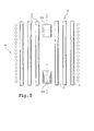
- Figure 1 shows a longitudinal section along the line BB of Figure 2 of a heat exchanger 100 according to the invention.
- a plurality 2 of tubes 3 preferably parallel to each other as shown in Figure 1 is surrounded on part of its length of one or preferably more than one inductive winding 4.
- Each winding is equipped with connecting means electrical power not shown at a non-current source represented.
- the straight sections of conductors constituting or preferably inductive windings 4 are symbolized by dots black.
- Tubes 3 are straight, of equal length and parallel to an axial direction OO 'of the plurality 2 of tubes 3.
- the tubes 3 are preferably as represented in FIGS. 1 and 2 arranged according to a symmetry of revolution around the axis OO '.
- Each tube 3 has two ends a first 5, and a second 6.
- From preferably the tubes 3 are equipped between their two extremes at least for some of them sensors 18 temperature.
- Preferably at least one of the tubes 3 is provided with several sensors 18 of temperature along its length.
- Each of the first ends 5 is embedded in a tubular plate 7 so that a fluid can pass through this plate and be in communication with the inside of the tubes 3.
- each of the second ends 6 is embedded in a tubular plate 8 so that a fluid can pass through this plate 8 and be in communication with the inside of the tubes 3.
- the plate tubular 7 is equipped with a non-through hole 28 centered on the axis OO '.
- a 9 shaped structure funnel is constituted by a frustoconical wall 10 centered on the axis OO '.
- the frustoconical wall 10 has a first end 11 having a wide opening and a second end 12 having a narrow opening. The openings are qualified wide and narrow one by report to the other.
- the first end 11 of the wall frustoconical 10 having a wide opening is extended by a cylindrical wall 13 which is embedded in sealed way in the non-through hole 28 of the tubular plate 7.
- the second end 12 of the wall frustoconical 10 having a narrow opening is extended by a cylindrical wall 14.
- the wall cylindrical 14 forms a conduit 14 for evacuation of a fluid from the tubes 3.
- the conduit 14 has a valve 15 to open or close the conduit.
- the conduit 14 is terminated by means 17 connection to connect the exchanger to an outer conduit not shown.
- a structure 9 'in the form of a funnel is constituted by a frustoconical wall 10 'centered on the axis OO '.
- the frustoconical wall 10 ' has a first end 11 'having a wide opening and a second end 12 'having a narrow opening.
- the first one end 11 'of the frustoconical wall 10' having a wide opening is extended by a cylindrical wall 13 'sealingly fit into a hole 28 'of the tubular plate 8.
- the second end 12 'of the frustoconical wall 10' having a narrow opening is extended by a wall cylindrical 14 '.
- the cylindrical wall 14 ' forms a conduit 14 'for supplying a fluid to be heated from the outside towards the inside of the tubes 3 through the tube plate 8.
- the conduit 14 ' may comprise a valve to open or close the conduit 14 '.
- the conduit 14 ' is terminated by means 17' of connection to connect the exchanger 100 to an outer conduit not shown.
- tubes 3 are in one piece inside and out the cylindrical volume defined by the inductor windings 4. There is no plate tubular positioning or connection of tubes 3 in and around the volume cylindrical delimited by the inductor windings 4.
- Tubular plates 7 and 8, to which are connected respectively the first 5 and second 6 ends of the tubes 3, are located outside the cylindrical volume delimited by the windings inductors 4 and its immediate vicinity.
- welds or solder connections ends tubes 3 to tubular plates 7 and 8 are outside the heated zone by induced currents. In this way the temperature of these connections is never greater than the temperature of the material to heat.
- the tubes 3 do not touch, at least in the volume cylindrical delimited by the inductor windings 4.
- the induced currents are specific to each tube and that we better control the contribution of energy tube by tube.
- the tubular plate 7 has 4 arms 16 of mechanical holding of turns constituting together the the inductive windings 4. These arms 16 are arranged perpendicular to the plate 7, that is to say parallel to the axis OO '.
- FIG. 2 is a cross-section according to the line AA of the exchanger example shown in FIG. It is intended to show an example of of tubes 3 relative to each other. Naturally other configurations are possible.
- the tubes 3 have the same diameter. This characteristic is not mandatory makes it easier to manufacture and supplies.
- the centers of the tube sections are located on concentric circles centered on the axis OO '.
- the centers of the sections of the tubes 3 are located at the vertices of a regular registered polygon in the circle.
- the polygons are, on each circle, octagons, in so that there is the same number of tubes, ie 8 tubes 3, centered on each circle.
- In total there are 40 tubes 3. Because near the center the diameters of the circles are smaller, the density of tubes is more large in the center than on the periphery of the interchange.
- the tubes of two circles immediately adjacent to each other are arranged in staggered relation to each other.
- a heat-treated fluid is sent by the supply means 9 'in the tubes 3 through of the tube plate 8 and is evacuated by the means 9 through the tubular plate 7. From preferably the heating of the fluid is carried out in continuous, that is to say that the evacuation valve and possibly a supply valve are open and that the fluid enters and leaves the exchanger permanently according to a continuous movement. Naturally circulation of the fluid introduced into the exchanger, could be discontinuous. In this case the fluid is immobilized during a heating period then evacuated. Each of the windings 4 is crossed by a variable current that induces currents in the tubes 3. These tubes heat up. During the duration of the contact with the tubes 3, the fluid is heated by the tubes 3. The fluid becomes hotter and warmer as it gets closer to the structure evacuation 9.
- the temperature sensors 18 are a part of a loop temperature control to control the temperature of the tubes 3 around the area where find the temperature sensor.
- a referenced 31 is equipped with a first sensor 18-1 located at a first level and a second sensor 18-2 located at a second level.
- Windings 41, 42 independent of each other, are located substantially to the right of the sensors 18-1, 18-2 respectively.
- source S1 includes means of regulation in themselves known and not represented receiving the indication of temperature or the temperature difference from a value theoretical. Because the power source S1 electric winding 41 is independent, it is possible to change the amount of heat transmitted the exchanger only at the level where the sensor 18-1. The same goes for the area around the 18-2 sensor, its independent winding 42 and its power source not shown S2. Naturally the number of sensors along a tube is not limited.
- the winding located at this level can be controlled by running the value of a combination involving different values measured by different sensors located at this level.
- one or more tubes are equipped with one or several temperature sensors each having a output coupled to control means of the electrical power supplying one or more windings.
- a or more temperature sensors at the level example of the evacuation conduit 14 of fluid and drive one or more sources depending on the values or deviations of values determined from these sensors.
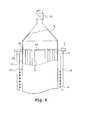
- FIG. 4 represents the upper part of a heat exchanger as shown in FIG. 1.
- elements having the same function as those described in connection with Figure 1 bear the same numbers of reference. It will not be described again.
- the plate tubular 7 has an upper non-through hole 28 as described with reference to FIG. allowing the tight connection of the structure of connection 9. It also has a hole lower through 20 for connection sealing of a cylindrical wall 21.
- the wall cylindrical 21 surrounds the plurality 2 of tubes 3.
- the cylindrical wall 21 is also connected so tight to the bottom tube plate 8.
- Each of the upper and lower tubular plates 8 is pierced through holes 22 in the plate portion being both inside the game delimited by the connection structure 9, 9 ' respectively and within the bounded area through the cylindrical wall 21.
- This configuration allows to fluid arriving through the connection structure 9 'to be introduced through through holes 22' of the plate 7 in a heating enclosure delimited by the cylindrical wall 21 and the tubular plates 7, 8, then discharged to the connection structure 9 by through holes 22.
- an enclosure surrounds so the plurality of tubes 2.
- This enclosure has openings putting her in communication with the first connection structure 9 connected to the first led 14 and with the second structure 9 'of connected to the second conduit 14 'so that a fluid can be introduced and evacuated the enclosure having been in contact with the surface outer and inner tubes 2. If in this variant of realization, for some reason, for example for cleaning difficulties, we do not want to pass the fluid in the tubes 2, it is enough that the tubes 2 do not open into the structures of connection 9, 9 '.
- the cylindrical wall 21 can be conductive on a part of its surface, ie formed by conductive parts interconnected by non-conductive parts. It can also be weakly conductive or non-conductive electricity.
- the bottom line is that it does not prevent the induced currents in the tubes 2 by the inductive currents flowing in the windings inductors 4.
Landscapes
- Physics & Mathematics (AREA)
- Electromagnetism (AREA)
- General Induction Heating (AREA)
- Manufacture And Refinement Of Metals (AREA)
Applications Claiming Priority (2)
| Application Number | Priority Date | Filing Date | Title |
|---|---|---|---|
| FR0111041A FR2828980B1 (fr) | 2001-08-23 | 2001-08-23 | Echangeur thermique a induction |
| FR0111041 | 2001-08-23 |
Publications (2)
| Publication Number | Publication Date |
|---|---|
| EP1286565A1 true EP1286565A1 (de) | 2003-02-26 |
| EP1286565B1 EP1286565B1 (de) | 2009-04-22 |
Family
ID=8866680
Family Applications (1)
| Application Number | Title | Priority Date | Filing Date |
|---|---|---|---|
| EP02292065A Expired - Lifetime EP1286565B1 (de) | 2001-08-23 | 2002-08-21 | Induktionswärmetauscher |
Country Status (5)
| Country | Link |
|---|---|
| EP (1) | EP1286565B1 (de) |
| AT (1) | ATE429797T1 (de) |
| DE (1) | DE60232048D1 (de) |
| ES (1) | ES2326261T3 (de) |
| FR (1) | FR2828980B1 (de) |
Cited By (1)
| Publication number | Priority date | Publication date | Assignee | Title |
|---|---|---|---|---|
| CN100394120C (zh) * | 2005-12-16 | 2008-06-11 | 王文生 | 一种电磁感应热管 |
Families Citing this family (1)
| Publication number | Priority date | Publication date | Assignee | Title |
|---|---|---|---|---|
| DE102016119668A1 (de) | 2016-10-14 | 2018-04-19 | Heinrich Graucob | Induktiver Wärmespeicher und Verfahren zur Umwandlung von thermischer Energie in elektrische Energie |
Citations (5)
| Publication number | Priority date | Publication date | Assignee | Title |
|---|---|---|---|---|
| US4017701A (en) * | 1972-02-29 | 1977-04-12 | Illinois Tool Works Inc. | Induction heating unit with combined tank circuit and heating coil |
| DE2745135A1 (de) * | 1977-10-07 | 1979-04-12 | Kali Chemie Ag | Induktionswaermetauscher |
| US4341936A (en) * | 1979-12-17 | 1982-07-27 | Virgin George C | Electromagnetic induction energy converter |
| DE3314824A1 (de) * | 1983-04-23 | 1984-10-31 | Otto Junker Gmbh, 5107 Simmerath | Vorrichtung zur erhitzung des innenraumes von behaeltern |
| FR2568083A1 (fr) * | 1984-07-20 | 1986-01-24 | Michel Dentroux | Perfectionnements apportes aux dispositifs de chauffage de fluide par induction. |
Family Cites Families (1)
| Publication number | Priority date | Publication date | Assignee | Title |
|---|---|---|---|---|
| US4359620A (en) * | 1977-12-06 | 1982-11-16 | Amp Incorporated | Induction heating apparatus |
-
2001
- 2001-08-23 FR FR0111041A patent/FR2828980B1/fr not_active Expired - Lifetime
-
2002
- 2002-08-21 DE DE60232048T patent/DE60232048D1/de not_active Expired - Lifetime
- 2002-08-21 EP EP02292065A patent/EP1286565B1/de not_active Expired - Lifetime
- 2002-08-21 ES ES02292065T patent/ES2326261T3/es not_active Expired - Lifetime
- 2002-08-21 AT AT02292065T patent/ATE429797T1/de not_active IP Right Cessation
Patent Citations (5)
| Publication number | Priority date | Publication date | Assignee | Title |
|---|---|---|---|---|
| US4017701A (en) * | 1972-02-29 | 1977-04-12 | Illinois Tool Works Inc. | Induction heating unit with combined tank circuit and heating coil |
| DE2745135A1 (de) * | 1977-10-07 | 1979-04-12 | Kali Chemie Ag | Induktionswaermetauscher |
| US4341936A (en) * | 1979-12-17 | 1982-07-27 | Virgin George C | Electromagnetic induction energy converter |
| DE3314824A1 (de) * | 1983-04-23 | 1984-10-31 | Otto Junker Gmbh, 5107 Simmerath | Vorrichtung zur erhitzung des innenraumes von behaeltern |
| FR2568083A1 (fr) * | 1984-07-20 | 1986-01-24 | Michel Dentroux | Perfectionnements apportes aux dispositifs de chauffage de fluide par induction. |
Cited By (1)
| Publication number | Priority date | Publication date | Assignee | Title |
|---|---|---|---|---|
| CN100394120C (zh) * | 2005-12-16 | 2008-06-11 | 王文生 | 一种电磁感应热管 |
Also Published As
| Publication number | Publication date |
|---|---|
| ES2326261T3 (es) | 2009-10-06 |
| FR2828980B1 (fr) | 2004-01-09 |
| EP1286565B1 (de) | 2009-04-22 |
| FR2828980A1 (fr) | 2003-02-28 |
| ATE429797T1 (de) | 2009-05-15 |
| DE60232048D1 (de) | 2009-06-04 |
Similar Documents
| Publication | Publication Date | Title |
|---|---|---|
| EP0079266B1 (de) | Einrichtung zum Induktionsschmelzen von dielektrischen Substanzen wie z.B. Glas oder Email | |
| EP2883006A1 (de) | Vorrichtung zum induktiven erwärmen eines warmwasserbereiters und warmwasserbereiter mit solch einer vorrichtung | |
| EP0056915B1 (de) | Anlage zum direkten Induktionsschmelzen in einem gekühlten Tiegel mit zusätzlicher elektromagnetischer Halterung des Schmelzgutes | |
| EP0914751A1 (de) | Induktionsofen zum schmelzen von glas unter verwendung eines kalten tiegels | |
| EP1286565B1 (de) | Induktionswärmetauscher | |
| EP0053070A1 (de) | Metallurgische Pfanne zum induktiven Behandeln von Metallen | |
| EP0418179B1 (de) | Elektrischer Kessel mit hydraulischer Turbulenz | |
| CA1092200A (fr) | Four electrique a haute frequence | |
| FR2665249A1 (fr) | Four de fusion par induction en creuset froid. | |
| CH618785A5 (de) | ||
| EP2883005B1 (de) | Anordnung aus einem wassererhitzer mit einem eine wassermenge umfassenden erhitzer und aus wenigstens einem generator eines für ein elektrisches gerät gewidmeten induktivmodules | |
| EP0476311A1 (de) | Elektrischer Fluiderhitzer | |
| FR2533154A1 (fr) | Procede pour braser par induction un assemblage complexe, et en particulier, un echangeur de chaleur | |
| CA1236152A (fr) | Generateur electrique de vapeur | |
| EP0082095A1 (de) | Anlage zum Erwärmen und/oder Umrühren und/oder Überführen von Metallen in flüssigem Zustand | |
| FR2512525A1 (fr) | Appareil de rechauffage d'un liquide a serpentin | |
| EP0088683A1 (de) | Elektrischer Ofen für hohe Temperatur, dessen Widerstände aus senkrechten, leitenden Heizröhren bestehen, die durch gekühlte Befestigungsröhren gehalten werden | |
| EP0232661B1 (de) | Elektromagnetische Pumpe für leitende Flüssigkeit mit Zurückdrängung durch magnetische Abstossung | |
| FR2787003A1 (fr) | Friteuse a gaz avec cuve de rechauffage perfectionnee | |
| FR2634091A1 (fr) | Dispositif de chauffage d'un liquide en circulation par micro-ondes | |
| FR3001726A1 (fr) | Dispositif de fibrage de materiaux thermoplastiques | |
| EP0368712B1 (de) | Regelbarer elektrischer Leistungsgenerator und seine Anwendung zur Produktion einer warmen Flüssigkeit | |
| FR2866102A1 (fr) | Radiateur muni de plaques rayonnantes et procede de fabrication de ce radiateur | |
| FR3156629A3 (fr) | Resistance electrique chauffante emettant dans un demi espace . | |
| EP3394521A1 (de) | Warmwasserspeicher-mehrtank-brauchwasserheizer |
Legal Events
| Date | Code | Title | Description |
|---|---|---|---|
| PUAI | Public reference made under article 153(3) epc to a published international application that has entered the european phase |
Free format text: ORIGINAL CODE: 0009012 |
|
| AK | Designated contracting states |
Kind code of ref document: A1 Designated state(s): AT BE BG CH CY CZ DE DK EE ES FI FR GB GR IE IT LI LU MC NL PT SE SK TR |
|
| AX | Request for extension of the european patent |
Extension state: AL LT LV MK RO SI |
|
| 17P | Request for examination filed |
Effective date: 20030811 |
|
| AKX | Designation fees paid |
Designated state(s): AT BE BG CH CY CZ DE DK EE ES FI FR GB GR IE IT LI LU MC NL PT SE SK TR |
|
| RAP1 | Party data changed (applicant data changed or rights of an application transferred) |
Owner name: ELECTRICITE DE FRANCE |
|
| GRAP | Despatch of communication of intention to grant a patent |
Free format text: ORIGINAL CODE: EPIDOSNIGR1 |
|
| GRAP | Despatch of communication of intention to grant a patent |
Free format text: ORIGINAL CODE: EPIDOSNIGR1 |
|
| GRAS | Grant fee paid |
Free format text: ORIGINAL CODE: EPIDOSNIGR3 |
|
| GRAA | (expected) grant |
Free format text: ORIGINAL CODE: 0009210 |
|
| AK | Designated contracting states |
Kind code of ref document: B1 Designated state(s): AT BE BG CH CY CZ DE DK EE ES FI FR GB GR IE IT LI LU MC NL PT SE SK TR |
|
| REG | Reference to a national code |
Ref country code: GB Ref legal event code: FG4D Free format text: NOT ENGLISH |
|
| REG | Reference to a national code |
Ref country code: CH Ref legal event code: EP |
|
| REG | Reference to a national code |
Ref country code: IE Ref legal event code: FG4D |
|
| REF | Corresponds to: |
Ref document number: 60232048 Country of ref document: DE Date of ref document: 20090604 Kind code of ref document: P |
|
| NLV1 | Nl: lapsed or annulled due to failure to fulfill the requirements of art. 29p and 29m of the patents act | ||
| REG | Reference to a national code |
Ref country code: ES Ref legal event code: FG2A Ref document number: 2326261 Country of ref document: ES Kind code of ref document: T3 |
|
| PG25 | Lapsed in a contracting state [announced via postgrant information from national office to epo] |
Ref country code: PT Free format text: LAPSE BECAUSE OF FAILURE TO SUBMIT A TRANSLATION OF THE DESCRIPTION OR TO PAY THE FEE WITHIN THE PRESCRIBED TIME-LIMIT Effective date: 20090822 Ref country code: FI Free format text: LAPSE BECAUSE OF FAILURE TO SUBMIT A TRANSLATION OF THE DESCRIPTION OR TO PAY THE FEE WITHIN THE PRESCRIBED TIME-LIMIT Effective date: 20090422 Ref country code: AT Free format text: LAPSE BECAUSE OF FAILURE TO SUBMIT A TRANSLATION OF THE DESCRIPTION OR TO PAY THE FEE WITHIN THE PRESCRIBED TIME-LIMIT Effective date: 20090422 |
|
| PG25 | Lapsed in a contracting state [announced via postgrant information from national office to epo] |
Ref country code: SE Free format text: LAPSE BECAUSE OF FAILURE TO SUBMIT A TRANSLATION OF THE DESCRIPTION OR TO PAY THE FEE WITHIN THE PRESCRIBED TIME-LIMIT Effective date: 20090722 Ref country code: NL Free format text: LAPSE BECAUSE OF FAILURE TO SUBMIT A TRANSLATION OF THE DESCRIPTION OR TO PAY THE FEE WITHIN THE PRESCRIBED TIME-LIMIT Effective date: 20090422 |
|
| REG | Reference to a national code |
Ref country code: IE Ref legal event code: FD4D |
|
| PG25 | Lapsed in a contracting state [announced via postgrant information from national office to epo] |
Ref country code: DK Free format text: LAPSE BECAUSE OF FAILURE TO SUBMIT A TRANSLATION OF THE DESCRIPTION OR TO PAY THE FEE WITHIN THE PRESCRIBED TIME-LIMIT Effective date: 20090422 Ref country code: IE Free format text: LAPSE BECAUSE OF FAILURE TO SUBMIT A TRANSLATION OF THE DESCRIPTION OR TO PAY THE FEE WITHIN THE PRESCRIBED TIME-LIMIT Effective date: 20090422 Ref country code: CZ Free format text: LAPSE BECAUSE OF FAILURE TO SUBMIT A TRANSLATION OF THE DESCRIPTION OR TO PAY THE FEE WITHIN THE PRESCRIBED TIME-LIMIT Effective date: 20090422 Ref country code: EE Free format text: LAPSE BECAUSE OF FAILURE TO SUBMIT A TRANSLATION OF THE DESCRIPTION OR TO PAY THE FEE WITHIN THE PRESCRIBED TIME-LIMIT Effective date: 20090422 |
|
| PG25 | Lapsed in a contracting state [announced via postgrant information from national office to epo] |
Ref country code: SK Free format text: LAPSE BECAUSE OF FAILURE TO SUBMIT A TRANSLATION OF THE DESCRIPTION OR TO PAY THE FEE WITHIN THE PRESCRIBED TIME-LIMIT Effective date: 20090422 |
|
| PLBE | No opposition filed within time limit |
Free format text: ORIGINAL CODE: 0009261 |
|
| STAA | Information on the status of an ep patent application or granted ep patent |
Free format text: STATUS: NO OPPOSITION FILED WITHIN TIME LIMIT |
|
| BERE | Be: lapsed |
Owner name: ELECTRICITE DE FRANCE Effective date: 20090831 |
|
| 26N | No opposition filed |
Effective date: 20100125 |
|
| PG25 | Lapsed in a contracting state [announced via postgrant information from national office to epo] |
Ref country code: BG Free format text: LAPSE BECAUSE OF FAILURE TO SUBMIT A TRANSLATION OF THE DESCRIPTION OR TO PAY THE FEE WITHIN THE PRESCRIBED TIME-LIMIT Effective date: 20090722 Ref country code: MC Free format text: LAPSE BECAUSE OF NON-PAYMENT OF DUE FEES Effective date: 20090831 |
|
| REG | Reference to a national code |
Ref country code: CH Ref legal event code: PL |
|
| PG25 | Lapsed in a contracting state [announced via postgrant information from national office to epo] |
Ref country code: LI Free format text: LAPSE BECAUSE OF NON-PAYMENT OF DUE FEES Effective date: 20090831 Ref country code: CH Free format text: LAPSE BECAUSE OF NON-PAYMENT OF DUE FEES Effective date: 20090831 |
|
| PG25 | Lapsed in a contracting state [announced via postgrant information from national office to epo] |
Ref country code: BE Free format text: LAPSE BECAUSE OF NON-PAYMENT OF DUE FEES Effective date: 20090831 |
|
| PG25 | Lapsed in a contracting state [announced via postgrant information from national office to epo] |
Ref country code: GR Free format text: LAPSE BECAUSE OF FAILURE TO SUBMIT A TRANSLATION OF THE DESCRIPTION OR TO PAY THE FEE WITHIN THE PRESCRIBED TIME-LIMIT Effective date: 20090723 |
|
| PG25 | Lapsed in a contracting state [announced via postgrant information from national office to epo] |
Ref country code: LU Free format text: LAPSE BECAUSE OF NON-PAYMENT OF DUE FEES Effective date: 20090821 |
|
| PG25 | Lapsed in a contracting state [announced via postgrant information from national office to epo] |
Ref country code: TR Free format text: LAPSE BECAUSE OF FAILURE TO SUBMIT A TRANSLATION OF THE DESCRIPTION OR TO PAY THE FEE WITHIN THE PRESCRIBED TIME-LIMIT Effective date: 20090422 |
|
| PG25 | Lapsed in a contracting state [announced via postgrant information from national office to epo] |
Ref country code: CY Free format text: LAPSE BECAUSE OF FAILURE TO SUBMIT A TRANSLATION OF THE DESCRIPTION OR TO PAY THE FEE WITHIN THE PRESCRIBED TIME-LIMIT Effective date: 20090422 |
|
| REG | Reference to a national code |
Ref country code: FR Ref legal event code: PLFP Year of fee payment: 15 |
|
| REG | Reference to a national code |
Ref country code: FR Ref legal event code: PLFP Year of fee payment: 16 |
|
| PGFP | Annual fee paid to national office [announced via postgrant information from national office to epo] |
Ref country code: ES Payment date: 20170919 Year of fee payment: 16 Ref country code: DE Payment date: 20170817 Year of fee payment: 16 Ref country code: GB Payment date: 20170822 Year of fee payment: 16 Ref country code: FR Payment date: 20170831 Year of fee payment: 16 Ref country code: IT Payment date: 20170809 Year of fee payment: 16 |
|
| REG | Reference to a national code |
Ref country code: DE Ref legal event code: R119 Ref document number: 60232048 Country of ref document: DE |
|
| GBPC | Gb: european patent ceased through non-payment of renewal fee |
Effective date: 20180821 |
|
| PG25 | Lapsed in a contracting state [announced via postgrant information from national office to epo] |
Ref country code: DE Free format text: LAPSE BECAUSE OF NON-PAYMENT OF DUE FEES Effective date: 20190301 Ref country code: IT Free format text: LAPSE BECAUSE OF NON-PAYMENT OF DUE FEES Effective date: 20180821 |
|
| PG25 | Lapsed in a contracting state [announced via postgrant information from national office to epo] |
Ref country code: FR Free format text: LAPSE BECAUSE OF NON-PAYMENT OF DUE FEES Effective date: 20180831 |
|
| REG | Reference to a national code |
Ref country code: ES Ref legal event code: FD2A Effective date: 20190918 |
|
| PG25 | Lapsed in a contracting state [announced via postgrant information from national office to epo] |
Ref country code: GB Free format text: LAPSE BECAUSE OF NON-PAYMENT OF DUE FEES Effective date: 20180821 Ref country code: ES Free format text: LAPSE BECAUSE OF NON-PAYMENT OF DUE FEES Effective date: 20180822 |