EP1286718B1 - Catheter de blocage - Google Patents
Catheter de blocage Download PDFInfo
- Publication number
- EP1286718B1 EP1286718B1 EP01930469A EP01930469A EP1286718B1 EP 1286718 B1 EP1286718 B1 EP 1286718B1 EP 01930469 A EP01930469 A EP 01930469A EP 01930469 A EP01930469 A EP 01930469A EP 1286718 B1 EP1286718 B1 EP 1286718B1
- Authority
- EP
- European Patent Office
- Prior art keywords
- proximal
- proximal member
- luer connector
- elongated body
- elongated
- Prior art date
- Legal status (The legal status is an assumption and is not a legal conclusion. Google has not performed a legal analysis and makes no representation as to the accuracy of the status listed.)
- Expired - Lifetime
Links
Images


Classifications
-
- A—HUMAN NECESSITIES
- A61—MEDICAL OR VETERINARY SCIENCE; HYGIENE
- A61M—DEVICES FOR INTRODUCING MEDIA INTO, OR ONTO, THE BODY; DEVICES FOR TRANSDUCING BODY MEDIA OR FOR TAKING MEDIA FROM THE BODY; DEVICES FOR PRODUCING OR ENDING SLEEP OR STUPOR
- A61M25/00—Catheters; Hollow probes
-
- A—HUMAN NECESSITIES
- A61—MEDICAL OR VETERINARY SCIENCE; HYGIENE
- A61M—DEVICES FOR INTRODUCING MEDIA INTO, OR ONTO, THE BODY; DEVICES FOR TRANSDUCING BODY MEDIA OR FOR TAKING MEDIA FROM THE BODY; DEVICES FOR PRODUCING OR ENDING SLEEP OR STUPOR
- A61M25/00—Catheters; Hollow probes
- A61M25/01—Introducing, guiding, advancing, emplacing or holding catheters
- A61M25/02—Holding devices, e.g. on the body
- A61M25/04—Holding devices, e.g. on the body in the body, e.g. expansible
-
- A—HUMAN NECESSITIES
- A61—MEDICAL OR VETERINARY SCIENCE; HYGIENE
- A61B—DIAGNOSIS; SURGERY; IDENTIFICATION
- A61B17/00—Surgical instruments, devices or methods
- A61B17/04—Surgical instruments, devices or methods for suturing wounds; Holders or packages for needles or suture materials
- A61B17/0483—Hand-held instruments for holding sutures
-
- A—HUMAN NECESSITIES
- A61—MEDICAL OR VETERINARY SCIENCE; HYGIENE
- A61M—DEVICES FOR INTRODUCING MEDIA INTO, OR ONTO, THE BODY; DEVICES FOR TRANSDUCING BODY MEDIA OR FOR TAKING MEDIA FROM THE BODY; DEVICES FOR PRODUCING OR ENDING SLEEP OR STUPOR
- A61M25/00—Catheters; Hollow probes
- A61M25/01—Introducing, guiding, advancing, emplacing or holding catheters
- A61M25/0105—Steering means as part of the catheter or advancing means; Markers for positioning
- A61M25/0133—Tip steering devices
- A61M2025/0163—Looped catheters
-
- A—HUMAN NECESSITIES
- A61—MEDICAL OR VETERINARY SCIENCE; HYGIENE
- A61M—DEVICES FOR INTRODUCING MEDIA INTO, OR ONTO, THE BODY; DEVICES FOR TRANSDUCING BODY MEDIA OR FOR TAKING MEDIA FROM THE BODY; DEVICES FOR PRODUCING OR ENDING SLEEP OR STUPOR
- A61M25/00—Catheters; Hollow probes
- A61M25/01—Introducing, guiding, advancing, emplacing or holding catheters
- A61M25/09—Guide wires
- A61M2025/09125—Device for locking a guide wire in a fixed position with respect to the catheter or the human body
Definitions
- the invention relates generally to catheters and more particularly to pigtail locking catheters.
- Kidney catheterization and bladder catheterization are medical procedures that permit drainage of the kidney or bladder after surgery or when the urinary system is blocked by an obstruction.
- Catheters designed for draining the bladder can be inserted percutaneously by first piercing the lower abdominal wall with a large hypodermic needle, fitting a cannula over the needle, and then placing the catheter within the bladder.
- the kidney can be accessed percutaneously through the middle of the back of the patient.
- Catheters are also used to drain other viscera such as the abdominal cavity, the stomach, and the biliary system.
- a catheter with a pigtail loop at its distal end is often used. After the catheter is inserted into the kidney or bladder, the pigtail loop is formed at a distal section of the catheter by pulling on a proximal end of a suture. The suture extends through and out of the catheter. A proximal portion of the suture is then secured to hold it in place and retain the loop shape at the distal section of the catheter.
- a further lockable catheter is described in US 5,989,241, which discloses a catheter having an elongated hollow drainage member, a flexible tip, a sealing member, a restraining member and a flexible drawing member.
- the flexible drawing member extends along the length of the hollow drainage member and is used to alter the configuration of the flexible tip, thereby facilitating the retention of the catheter within a patient's body.
- the invention relates generally to locking catheters and methods for using such locking catheters.
- the invention involves a locking catheter.
- the locking catheter includes an elongated body member which defines a central lumen.
- the elongated body includes a distal portion and a proximal portion where at least a portion of the elongated body is for placement within a patient.
- the locking catheter further includes a first proximal member disposed at the proximal portion of the elongated body member and defines a central passageway which extends therethrough and is coaxial with the lumen.
- the locking catheter further includes an elongated flexible member.
- the elongated flexible member includes a first end and a second end.
- the first end is coupled to the distal portion of the elongated body member and extends through both at least a portion of the central lumen of the elongated body member and the central passageway of the first proximal member.
- the second end is disposed external to the elongated body member.
- the locking catheter further includes a second proximal member releasably couplable to the first proximal member to allow selective locking and unlocking of the elongated flexible member therebetween.
- the second proximal member defines a central passageway which extends therethrough and a separate channel which also extends therethrough.
- the elongated flexible member extends through the separate channel and is slidable therethrough to allow the distal portion of the elongated body member to be drawn toward the proximal portion of the elongated body member to form a loop in the distal portion when the first and second proximal members are decoupled.
- the central passageway of the second proximal member extends coaxially from the central passageway of the first proximal member and the elongated flexible member is compressed between the first and second proximal members and is non-slidable through the separate channel to secure the loop when the first and second proximal members are coupled together.
- the locking catheter further comprises a grommet which defines a central passageway extending therethrough.
- the grommet is disposed between the first proximal member and the second proximal member with the central passageway of the grommet coaxial with the central passageway of the second proximal member.
- the grommet creates a seal between the first proximal member and the second proximal member when the first proximal member is coupled to the second proximal member.
- the grommet also defines a channel extending therethrough and the elongated flexible member extends through the channel of the grommet.
- first proximal member is a female luer connector and the second proximal member is a male luer connector.
- the central lumen of the elongated body member, the central passageway of the first proximal body, and the central passageway of the second proximal body are configured to receive a stylet.
- the elongated member comprises plastic.
- the elongated member includes a plurality of apertures for allowing fluid to flow into and out of the central lumen of the elongated member.
- the first proximal member includes a valve which is open when the first proximal member is coupled to the second proximal member, and which is closed when the first proximal member is decoupled from the second proximal member.
- the first proximal member includes a ratchet and the second proximal member includes teeth.
- the ratchet engages the teeth when the second proximal member is coupled to the first proximal member and prevents the second proximal member from inadvertently decoupling from the first proximal member.
- the first proximal member includes one of a male and female latch and the second proximal member includes the other of a male and female latch.
- the male latch includes a prong and the female latch includes a notch. The male latch engages the female latch when the first proximal member is coupled to the second proximal member and prevents the first proximal member from inadvertently decoupling from the second proximal member.
- the first proximal member includes a first latch which includes a first set of teeth and the second proximal member includes a second latch which includes a second set of teeth.
- the first set of teeth engages the second set of teeth when the first proximal member is coupled to the second proximal member and prevents the first proximal member from inadvertently decoupling from the second proximal member.
- the second proximal member includes a spool to wind the elongated flexible member therearound when the second proximal member is coupled to the first proximal member.
- the locking catheter further includes a second elongated body member which defines a central lumen extending therethrough.
- the elongated body member includes a first port and a second port.
- the first port is removably couplable to the second proximal member and extends coaxially from the central passageway of the second proximal member.
- the second port is connectable to a device external to the patient.
- the first port includes a valve for sealing the central passageway of the second proximal member when the second port is decoupled from the device external to the patient.
- the valve is a stopcock.
- the invention in still another aspect, involves a locking catheter.
- the locking catheter includes an elongated body member defining a central lumen and comprising a distal portion and a proximal portion, where at least a portion of the elongated body member is for placement within a patient.
- the locking catheter further includes a first proximal member disposed at the proximal portion of the elongated body member and defines a central passageway extending therethrough and a separate channel extending therethrough.
- the central passageway of the first proximal member is coaxial with the lumen.
- the locking catheter further includes an elongated flexible member.
- the elongated flexible member includes a first end and a second end.
- the first end is coupled to the distal portion of the elongated body member and the elongated flexible member extends through at least a portion of the central lumen of the elongated body member, the central passageway of the first proximal member, and the separate channel.
- the elongated flexible member is slidable through the separate channel to allow the distal portion of the elongated body member to be drawn toward the proximal portion of the elongated body member to form a loop in the distal portion, with the second end disposed external to the elongated body member.
- the locking catheter further comprises a second proximal member releasably couplable to the first proximal member to allow selective locking and unlocking of the elongated flexible member therebetween.
- the second proximal member defines a central passageway extending therethrough, and the central passageway of the second proximal member extends coaxially from the central passageway of the first proximal member.
- the elongated flexible member is compressed between the first and second proximal members and is non-slidable through the separate channel and secures the loop when the first and second proximal members are coupled together.
- the present invention is used to drain viscera such as the kidneys, bladder, abdominal cavity, the stomach, and the biliary system.
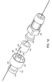
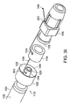
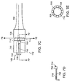
- the pigtail-locking catheter 100 includes an elongated body member 102, a female luer connector 106, a male luer connector 112, and an elongated flexible member 104.
- the elongated body member 102 includes a plurality of apertures 110 disposed along the length of the elongated body member 102 and in the distal portion 125, and a central lumen 131 that extends the entire length of the elongated body member 102.
- the plurality of apertures 110 provide access to the central lumen 131 to facilitate fluid flow into and/or out of the elongated body member 102.
- the female luer connector 106 includes an opening 108 and a rim 308.
- the male luer connector 112 includes an inner wall 134 and a cap 122.
- the elongated flexible member 104 is coupled to a distal portion 125 of the elongated body member 102, extends outside of the elongated body member 102 through a distal opening 130, and reenters the elongated body member 102 through another opening 128 disposed in a middle section of the elongated body member 102.
- the elongated flexible member 104 extends inside the elongated body member 102 through the opening 128 and along the central lumen 131 of the elongated body member 102 to the proximal end 126 of the elongated body member 102.
- the elongated flexible member 104 tied to the distal portion 125.
- the elongated flexible member 104 can be glued to the distal portion 125 or formed in the distal portion 125.
- the elongated flexible member 104 is coupled to the female luer connector 106 and extends through the elongated body member 102 to the distal portion 125.
- the elongated flexible member 104 extends outside the elongated body member 102 through the distal opening 130 and reenters the elongated body member 102 through another opening 128 disposed in a middle section of the elongated body member 102.
- the elongated flexible member 104 extends inside the elongated body member 102 from the opening 128 and along the central lumen 131 of the elongated body member 102 to the proximal end 126 of the elongated body member 102.
- the elongated flexible member 104 can be glued to the female luer connector 106 or formed in the female luer connector 106.
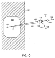
- the distal portion 125 of the elongated body member 102 straightened with a stiffening stylet 166 disposed within the central lumen 131 of the elongated body member 102 is inserted into a patient's bladder, for example, over a guidewire 168.
- the stiffening stylet 166 and the guidewire 168 are removed from the patient's body leaving the distal portion 125 of the elongated body member 102 disposed within the patient's bladder.
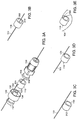
- the male luer connector 112 is decoupled from the female luer connector 106.
- the elongated flexible member 104 is pulled through a channel 118 in the male luer connector 112 to draw the distal portion 125 of the elongated body member toward the proximal portion 126 of the elongated body member to form a loop in the elongated body portion 102.
- the male luer connector 112 is moved toward the female luer connector 106 until the male luer connector 112 engages the female luer connector 106.
- an inner wall 134 of the male luer connector 112 is inserted into an opening 108 of the female luer connector 106.
- the elongated flexible member 104 is compressed between the rim 308 of the opening 108 and the cap 122 of the male luer connector 112 thereby locking the elongated flexible member 104 in place and locking the distal portion 125 of the elongated body member 102 in the looped position.
- the female luer connector 106 is coupled to the proximal portion 126 of the elongated body member 102 and includes a central passageway that extends therethrough which is coaxial with the central lumen 131 of the elongated body member 102.
- the elongated flexible member 104 extends through the central passageway of female luer connector 106 and out of a proximal opening 108.
- the elongated flexible member 104 is a suture thread made of nylon or other similar material of comparable strength.
- the elongated flexible member 104 can be a thread or a flexible metal wire.
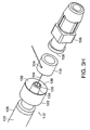
- the male luer connector 112 includes an inner wall 134 defining a central passageway 120 that extends therethrough, a cap 122 defining a space 132 between the inner wall 134, and a channel 118 located in a wall of the cap 120.
- the elongated flexible member 104 extends into the space 132 of the male luer connector 112 and exits through the channel 118.
- the elongated flexible member 104 includes a knot 105 disposed at the proximal end of the elongated flexible member 104 to prevent the elongated flexible member 104 from sliding out of the channel 118 or the male luer connector 112 from being loose or lost.
- the elongated flexible member 104 slides through the channel 118 and allows the distal portion 125 to be drawn toward the proximal portion 126 to form a loop in the distal portion 125.
- the male luer connector 112 is moved toward the female luer connector 106 until the male luer connector 112 engages the female luer connector 106.
- the inner wall 134 is inserted into the opening 108 of the female luer connector 106 with the central passageway 120 being coaxial with the central passageway in female luer connector 106.
- the elongated flexible member 104 is compressed between the rim 308 of the opening 108 and the cap 122 thereby locking the elongated flexible member 104 in place and locking the distal portion 125 of the elongated body member 102 in the pigtail position.
- the elongated flexible member 104 does not interfere with the seal between the male luer connector 112 and the female luer connector 106 when these two parts are coupled together and does not cause wicking along the elongated flexible member 104 and out of the catheter 100.
- the male luer connector 112 and the female luer connector 106 are made of molded bio-compatible plastic. In other embodiments, the male luer connector 112 and the female luer connector 106 are made of metal, such as surgical steel or aluminum. In still other embodiments, the male luer connector 112 and the female luer connector 106 need not be used and instead, other similar interference fit connectors can be used that will provide a seal and compress the elongated flexible member 104.
- the luer connector, male or female is fitted on the elongated body member 102 by force fitting, gluing, or molding. In some embodiments, the elongated body member 102 can be made of plastic, nylon, polyethylene, ethylene-vinyl acetate co-polymer, or similar material.
- a grommet 116 made of compressible material is placed inside the space 132 of the cap 122 surrounding the inner wall 134.
- the grommet 116 is compressed between the rim 308 of the opening 108 and the cap 122 and creates a seal between the male luer connector 112 and the female luer connector 106.
- the elongated flexible member 104 may radially extend through a channel 124 in the grommet 116.
- the grommet 116 When the male luer connector 112 engages the female luer connector 106, the grommet 116 is compressed and the grommet 116 thereafter compresses the elongated flexible member 104 (as shown in Fig. 4) thereby locking the elongated flexible member 104 in place and locking the distal portion 125 of the elongated body member 102 in the pigtail position.
- the elongated flexible member 104 may also be compressed and thereby locked by the grommet 116 in a variety of ways. Referring to Figs. 3B, in one embodiment, the elongated flexible member 104 extends through the central passageway 302 of the grommet 116 and is compressed between the interior surface 310 of the grommet 116 and the exterior surface of inner wall 134. Referring to Fig. 3C, in another embodiment, the elongated flexible member 104 extends between and is compressed by the exterior surface 312 of the grommet 116 and an interior surface 136 of the cap 122. Referring to Fig. 3D, in still another embodiment, the elongated flexible member 104 extends longitudinally through the wall of the grommet 116.
- the elongated flexible member 104 When the grommet 116 is compressed, the elongated flexible member 104 is compressed. Referring to Fig. 3E, in yet another embodiment, the elongated flexible member 104 is compressed between the distal face 306 of the grommet 116 and the rim 308 of the female luer connector 106.
- the grommet 116 is made of latex. In other embodiments, the grommet 116 can be made of silicone or foam.
- the benefit of using the grommet 116 between the male luer connector 112 and the female luer connector 106 is that a better seal is created between the male luer connector 112 and the female luer connector 106, wicking is prevented in the case where the elongated flexible member 104 is inadvertently compressed between the male luer connector 112 and the female luer connector 106, and the elongated flexible member 104 is held more securely thereby maintaining the loop in the distal portion 125 of the elongated body member 102.
- the positions of the female luer connector 106 and the male luer connector 112 may be reversed.
- the male luer connector 112 is coupled to the proximal portion 126 of the elongated body member 102, and the female luer connector 106 is releasably couplable to the male luer connector 112.
- the elongated flexible member 104 may also be compressed and thereby locked by the grommet 116 in a variety of ways as shown in Figs. 3F, 3G, and 3H.
- the elongated flexible member 104 exits the central passageway 120 of the male luer connector 112 through an opening 320 in the inner wall 134.
- the elongated flexible member 104 pass through the channel 124 in the grommet 116 and then passes through a passageway 322 in the female luer connector 106.
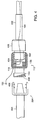
- the male luer connector 112 includes proximally a female luer portion 114 which is used to mate with a male luer connector 204 of a connection tube 202.
- the connection tube 202 is used to connect the locking-pigtail catheter 100 with a medical device such as a collecting bag, for example.
- the male luer connector 112 and the female luer connector 106 are threaded and are held together when the threads 402 of the male luer connector 112 engage the threads 404 of the female luer connector 106.
- the male luer connector 204 of connection tube 202 and the female luer portion 114 of the male luer connector 112 are also similarly threaded.
- the male luer connector 204 and the female portion 114 are held together when the threads 406 of the male luer connector 204 engage the threads 408 of the female luer portion 114.
- the patient may accidentally disengage the male luer connector 112 from the female luer connector 106 instead of disengaging the male luer connector 204 from the female portion 114 and thereby unlock the loop in the distal portion 125 and increase the risk of dislodging the catheter 100 from the body cavity.
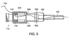
- various safety features may be incorporated into the male luer connector 112 and the female luer connector 106 and are discussed below.
- the male luer connector 112 includes a cap 504 which includes one or more prongs 506.
- the female luer connector 106 includes one or more notches 502. When the male luer connector 112 and the female luer connector 106 engage each other (by pushing or screwing them together, for example), the prongs 506 engage the notch 502 and prevent further rotational motion of the male luer connector 112 or the female luer connector 106 and the male luer connector 112 from being inadvertently disconnected from the female luer connector 106.
- the male luer connector 112 can only be disengaged from the female luer connector 106 when the cap 504 is squeezed radially and simultaneously at two diametrically opposed positions disposed at a ninety-degree angle from the prongs 506 thereby causing the prongs 506 to lift out of the notch 502.
- the notch 502 and the prongs 506 may extend circumferentially, and fitting and release may be done through rigorous pushing together and pulling apart.
- the male luer connector 112 freely rotates in either a clockwise or counterclockwise direction.
- the cap 602 includes an outside portion 608 and an inside portion 610.
- the outside portion 608 includes teeth 604 disposed on the inside proximal face and extending longitudinally.
- the inside portion 610 includes teeth 606 disposed on the outside proximal face and extending longitudinally but in the opposite direction of teeth 604.
- the outer portion 608 spins freely in the opposite (loosening) direction which prevents the male luer connector 112 from being inadvertently unscrewed and disconnected from the female luer connector 106.
- the male luer connector 112 can only be disengaged from the female luer connector 106 when the cap 602 is pressed toward the female luer connector 106 and turned in the loosening direction at the same time. Pressing the cap 602 toward the female luer connector 106 causes the outer portion 608 to move toward the inner portion 610 which causes the teeth 604 to engage the teeth 606 and allows the outer portion 608 to turn the inner portion 610 in the loosening direction.
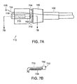
- the cap 708 includes a spring-loaded slidable ratchet 702 with a spring 706 and the slidable ratchet 702 mounted over a slide 710.
- the female luer connector 106 includes teeth 704 disposed on a proximal face and extending longitudinally.
- the teeth 712 in the spring-loaded ratchet 702 engage the teeth 704 and prevent the male luer connector 112 from being inadvertently unscrewed and disconnected from the female luer connector 106.
- the male luer connector 112 can only be disengaged from the female luer connector 106 when the spring-loaded ratchet 702 is pressed proximally so that the teeth 704 and 712 disengage while male luer connector 112 is turned.
- the cap 718 includes a spring-loaded slidable ratchet 702 with a spring 706 and the slidable ratchet 702 mounted over a slide 710.
- the female luer connector 106 includes holes (or notches) 716 disposed on a proximal face. When the male luer connector 112 and the female luer connector 106 engage each other by screwing them together, the pin 714 in the spring-loaded ratchet 702 engages one of the holes 716 and prevents the male luer connector 112 from being inadvertently unscrewed and disconnected from the female luer connector 106.
- the male luer connector 112 can only be disengaged from the female luer connector 106 when the spring-loaded ratchet 702 is pressed proximally so that the pin 714 disengages from one of the holes 716 while male luer connector 112 is turned.
- the cap 808 includes teeth 804, and the female luer connector 106 includes a flexible but resilient ratchet 802 which includes a tongue 810, a landing 812, and a pivot 814.
- the tongue 810 engages the teeth 804 and prevents the male luer connector 112 from being inadvertently unscrewed and disconnected from the female luer connector 106.
- the male luer connector 112 can only be disengaged from the female luer connector 106 when the landing 812 is pressed down radially thereby causing the tongue 810 to raise (outwardly via pivot 814) and then turning the male luer connector 112.
- the female luer connector 106 includes right-hand threads 906 and the female portion 114 of the male luer connector 112 includes left-hand threads 904.
- the male luer connector 112 and the female luer connector 106 engage each other by screwing together in one direction, and the male luer connector 204 on the connection tube 202 and the female portion 114 engage each other by screwing together in the opposite direction.
- connection tube 202 When the connection tube 202 is disconnected from the female portion 114 of the male luer connector 112, the male luer connector 204 is turned in a direction that tightens the connection between the male luer connector 112 and the female luer connector 106, thus preventing the male luer connector 112 from being inadvertently unscrewed and disconnected from the female luer connector 106 and releasing the elongated flexible member 104.
- the female luer connector 106 includes a rotatable connector coupled to the proximal portion 126 of the elongated body member 102.
- the rotatable connector includes a first rotating portion 912, a second rotating portion 914 coaxial with the first rotating portion 912, and rotation point 916 coaxial with rotating portions 912 and 914.
- Rotating portion 912 and 914 are independently rotatable in both the clockwise and counterclockwise directions.
- the male luer connector 112 and the female luer connector 106 are coupled together by screwing the male luer connector 112 to the female luer connector 106 while holding the rotating portion 912.
- the male luer connector 112 and the female luer connector 106 will rotate freely about the rotating point 916, The male luer connector 112 can only be disengaged from the female luer connector 106 by holding the rotating portion 912 while unscrewing the male luer connector 112. Inadvertently holding any other portion besides rotating portion 912 will prevent decoupling of the male luer connector 112 and the female luer connector 106.
- the cap 1010 includes teeth 1002 extending longitudinally from a distal face, and the female luer connector 106 includes a compressible member 1004 which includes teeth 1006.
- the teeth 1002 engage the teeth 1006 and prevent the male luer connector 112 from being inadvertently unscrewed and disconnected from the female luer connector 106.
- the male luer connector 112 can only be disengaged from the female luer connector 106 when the compressible member 1004 is compressed in a direction indicated by arrow 1008. Compressing the compressible member 1004 causes the teeth 1002 to disengage the teeth 1006 and allows the male luer connector 112 and the female luer connector 106 to be unscrewing.
- other safety locking mechanisms can be used to prevent the male luer connector 112 from being inadvertently unscrewed and disconnected from the female luer connector 106 and releasing the elongated flexible member 104. Additionally, all the components of the safety locking mechanisms previously described above that are part of the male luer connector 112 can be instead part of the female luer connector 106. Likewise, all the components of the safety locking mechanisms that are part of the female luer connector 106 can be instead part of the male connector 112.
- a stopcock valve is connected to and located between the connection tube 202 and the female portion 114 of the male luer connector 112.
- the stopcock valve is used to prevent leaking from the locking-pigtail catheter 100 when the connection tube 202 is disconnected from the female portion 114 or from a medical device.
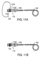
- the male luer connector 112 includes a spool 1102 for winding any excess elongated flexible member 104 extending out of the channel 118 of the male luer connector 112 when the male luer connector 112 is coupled to the female luer connector 106.
- the end 1104 of the elongated flexible member 104 is coupled to spool 1102.
- the spool 1102 can include a ratchet which prevents the spool 1102 from unwinding unless the ratchet is released, by pushing or pulling the spool 1102 longitudinally, for example.
- the spool 1102 may be a circumferential groove disposed in the male luer connector 112 with a slit in the side of the groove to secure the end 1104 of the elongated flexible member 104.
- the female luer connector 106 includes a valve disposed in the central passageway of the female luer connector 106. The valve is closed when the male luer connector 112 is decoupled from the female luer connector 106. When the male luer connector 112 engages the female luer connector 106, the inner wall 134 is inserted into the opening 108 of the female luer connector 106 thereby opening the valve disposed in the central passageway in female luer connector 106.
Landscapes
- Health & Medical Sciences (AREA)
- Life Sciences & Earth Sciences (AREA)
- Hematology (AREA)
- Animal Behavior & Ethology (AREA)
- Engineering & Computer Science (AREA)
- Anesthesiology (AREA)
- Biomedical Technology (AREA)
- Heart & Thoracic Surgery (AREA)
- Biophysics (AREA)
- Pulmonology (AREA)
- General Health & Medical Sciences (AREA)
- Public Health (AREA)
- Veterinary Medicine (AREA)
- Infusion, Injection, And Reservoir Apparatuses (AREA)
- External Artificial Organs (AREA)
- Media Introduction/Drainage Providing Device (AREA)
Claims (16)
- Cathéter de verrouillage, comprenant :un membre allongé (102) faisant office de corps définissant une lumière centrale (131) et comprenant une portion distale (125) et une portion proximale (126), au moins une portion du membre allongé faisant office de corps étant destinée à venir se placer au sein d'un patient ;un premier membre proximal (106) disposé à la portion proximale du membre allongé faisant office de corps et définissant un passage central (108) s'étendant à travers lui et en position coaxiale à la lumière (131) ;un membre flexible allongé (104) comprenant une première extrémité et une deuxième extrémité, la première extrémité étant couplée à la portion distale (125) du membre allongé faisant office de corps, le membre flexible allongé s'étendant à la fois à travers au moins une portion de la lumière centrale (131) du membre allongé faisant office de corps et à travers le passage central (108) du premier membre proximal, la deuxième extrémité pouvant être verrouillée à la portion terminale proximale et étant disposée à l'extérieur du membre allongé faisant office de corps ; caractérisé en ce que le cathéter comprend en outre :un deuxième membre proximal (112) apte à se coupler de manière amovible au premier membre proximal (106) pour permettre un verrouillage et un déverrouillage sélectifs du membre flexible allongé entre eux, le deuxième membre proximal (112) définissant un passage central (120) s'étendant à travers lui et un canal séparé (118) s'étendant à travers lui, le membre flexible allongé (104) s'étendant à travers le canal séparé (118) et étant à même de glisser à travers lui pour pouvoir tirer la portion distale (125) du membre allongé (102) faisant office de corps en direction de la portion proximale (126) du membre allongé (102) faisant office de corps pour former une boucle dans la portion distale (125) lorsque le premier membre proximal (106) et le deuxième membre proximal (112) sont découplés, le passage central (120) du deuxième membre proximal s'étendant en position coaxiale au passage central (108) du premier membre proximal et le membre flexible allongé (104) étant comprimé entre le premier membre proximal (106) et le deuxième membre proximal (112) et étant incapable de glisser à travers le canal séparé (118) afin de fixer la boucle lorsque le premier membre proximal (106) et le deuxième membre proximal (112) sont couplés l'un à l'autre.
- Cathéter de verrouillage selon la revendication 1, comprenant en outre un passant (116) définissant un passage central s'étendant à travers lui, le passant (116) étant disposé entre le premier membre proximal (106) et le deuxième membre proximal (112), le passage central du passant étant disposé en position coaxiale au passage central (120) du deuxième membre proximal (112), et créant un joint d'étanchéité entre le premier membre proximal (106) et le deuxième membre proximal (112) lorsque le premier membre proximal (106) est couplé au deuxième membre proximal (112).
- Cathéter de verrouillage selon la revendication 2, dans lequel le passant (116) définit également un canal (124) s'étendant à travers lui et dans lequel le membre flexible allongé (104) s'étend à travers le canal (124) du passant.
- Cathéter de verrouillage selon l'une quelconque des revendications précédentes, dans lequel le premier membre proximal (106) est un raccord Luer-Lok femelle et le deuxième membre proximal (112) est un raccord Luer-Lok mâle.
- Cathéter de verrouillage selon l'une quelconque des revendications précédentes, dans lequel la lumière centrale (131) du membre allongé faisant office de corps, le passage central (108) du premier membre proximal (106) et le passage central (120) du deuxième membre proximal (112) sont configurés pour recevoir un stylet.
- Cathéter de verrouillage selon l'une quelconque des revendications précédentes, dans lequel le membre allongé (102) comprend une matière plastique.
- Cathéter de verrouillage selon l'une quelconque des revendications précédentes, dans lequel le membre allongé (102) comprend plusieurs orifices (110) pour permettre le passage d'un fluide qui entre dans la lumière centrale (131) du membre allongé (102) et qui en ressort.
- Cathéter de verrouillage selon l'une quelconque des revendications précédentes, dans lequel le premier membre proximal (106) comprend une valve, la valve étant ouverte lorsque le premier membre proximal est couplé au deuxième membre proximal (112) et la valve étant fermée lorsque le premier membre proximal (106) est découplé du deuxième membre proximal (112).
- Cathéter de verrouillage selon l'une quelconque des revendications précédentes, dans lequel le premier membre proximal (106) comprend un cliquet (702) et le deuxième membre proximal (112) comprend des dents (704), le cliquet venant s'engrener avec les dents lorsque le deuxième membre proximal (112) est couplé au premier membre proximal (106) pour ainsi empêcher le découplage par inadvertance du deuxième membre proximal (112) du premier membre proximal (106).
- Cathéter de verrouillage selon l'une quelconque des revendications précédentes, dans lequel le premier membre proximal (106) comprend, soit un verrou mâle, soit un verrou femelle, et le deuxième membre proximal (112) comprend de manière correspondante soit un verrou femelle, soit un verrou mâle, le verrou mâle comprenant une patte (506), le verrou femelle comprenant une encoche (502), le verrou mâle venant s'engrener avec le verrou femelle lorsque le premier membre proximal (106) est couplé au deuxième membre proximal (112) pour ainsi empêcher le découplage par inadvertance du premier membre proximal (112) et du deuxième membre proximal (106).
- Cathéter de verrouillage selon l'une quelconque des revendications précédentes, dans lequel le premier membre proximal (106) comprend un premier verrou englobant un premier jeu de dents (704) et le deuxième membre proximal comprend un deuxième verrou englobant un deuxième jeu de dents (712), le premier jeu de dents (704) venant s'engrener avec le deuxième jeu de dents (712), lorsque le premier membre proximal (106) est couplé au deuxième membre proximal (112) pour ainsi empêcher le découplage par inadvertance du premier membre proximal (112) et du deuxième membre proximal (106).
- Cathéter de verrouillage selon l'une quelconque des revendications précédentes, dans lequel le deuxième membre proximal comprend une bobine (1102) pour y enrouler le membre flexible allongé (104) lorsque le deuxième membre proximal (112) est couplé au premier membre proximal (106).
- Cathéter de verrouillage selon l'une quelconque des revendications précédentes, comprenant en outre un deuxième membre allongé (202) faisant office de corps définissant une lumière centrale s'étendant à travers lui, le deuxième membre allongé (202) faisant office de corps comprenant un premier orifice et un deuxième orifice, le premier orifice étant à même de se coupler de manière amovible au deuxième membre proximal (112) et s'étendant en position coaxiale au passage central (120) du deuxième membre proximal (112), le deuxième orifice étant destiné à se raccorder à un dispositif à l'extérieur du patient.
- Cathéter de verrouillage selon la revendication 13, dans lequel le premier orifice comprend une valve pour fermer de manière étanche le passage central du deuxième membre proximal lorsque le deuxième orifice est découplé du dispositif à l'extérieur du patient.
- Cathéter de verrouillage selon la revendication 14, dans lequel la valve comprend un cran d'arrêt.
- Cathéter de verrouillage, comprenant :un membre allongé (102) faisant office de corps définissant une lumière centrale (131) et comprenant une portion distale (125) et une portion proximale (126), au moins une portion du membre allongé faisant office de corps étant destinée à venir se placer au sein d'un patient ;un premier membre proximal (106) disposé à la portion proximale du membre allongé faisant office de corps et définissant un passage central (108) s'étendant à travers lui et un canal séparé (118) s'étendant à travers lui, le passage central étant disposé en position coaxiale à la lumière (131) ; un membre flexible allongé (104) comprenant une première extrémité et une deuxième extrémité, la première extrémité étant couplée à la portion distale (125) du membre allongé faisant office de corps, le membre flexible allongé s'étendant à travers au moins une portion de la lumière centrale (131) du membre allongé faisant office de corps, à travers le passage central (108) du premier membre proximal, et à travers le canal séparé (118), et étant à même de glisser à travers le canal séparé (118) pour pouvoir tirer la portion distale (125) du membre allongé (102) faisant office de corps en direction de la portion proximale (126) du membre allongé (102) faisant office de corps pour former une boucle dans la portion distale (125), la deuxième extrémité pouvant être verrouillée à la portion proximale et étant disposée à l'extérieur du membre allongé faisant office de corps, caractérisé en ce que le cathéter comprend en outre :un deuxième membre proximal (112) apte à venir se coupler de manière amovible au premier membre proximal (106) pour permettre un verrouillage et un déverrouillage sélectifs du membre flexible allongé (104) entre eux, le deuxième membre proximal (112) définissant un passage central (120) s'étendant à travers lui, le passage central (120) du deuxième membre proximal s'étendant en position coaxiale au passage central (108) du premier membre proximal et le membre flexible allongé étant comprimé entre le premier membre proximal et le deuxième membre proximal et étant incapable de glisser à travers le canal séparé afin de fixer la boucle lorsque le premier membre proximal et le deuxième membre proximal sont couplés l'un à l'autre.
Applications Claiming Priority (3)
| Application Number | Priority Date | Filing Date | Title |
|---|---|---|---|
| US19593100P | 2000-04-10 | 2000-04-10 | |
| US195931P | 2000-04-10 | ||
| PCT/US2001/011693 WO2001076677A1 (fr) | 2000-04-10 | 2001-04-10 | Catheter de blocage |
Publications (2)
| Publication Number | Publication Date |
|---|---|
| EP1286718A1 EP1286718A1 (fr) | 2003-03-05 |
| EP1286718B1 true EP1286718B1 (fr) | 2007-01-24 |
Family
ID=22723419
Family Applications (1)
| Application Number | Title | Priority Date | Filing Date |
|---|---|---|---|
| EP01930469A Expired - Lifetime EP1286718B1 (fr) | 2000-04-10 | 2001-04-10 | Catheter de blocage |
Country Status (7)
| Country | Link |
|---|---|
| US (1) | US6699233B2 (fr) |
| EP (1) | EP1286718B1 (fr) |
| JP (1) | JP4741774B2 (fr) |
| AU (2) | AU2001257005B2 (fr) |
| CA (1) | CA2404440C (fr) |
| DE (1) | DE60126272T2 (fr) |
| WO (1) | WO2001076677A1 (fr) |
Families Citing this family (89)
| Publication number | Priority date | Publication date | Assignee | Title |
|---|---|---|---|---|
| US6852105B2 (en) * | 2000-11-01 | 2005-02-08 | Prostalund Operations Ab | Method and apparatus for insertion of self-draining urine apparatus into bladder |
| US7041090B2 (en) * | 2000-11-01 | 2006-05-09 | Prostalund Operations Ab | Method and apparatus for self-draining of urine |
| US8323228B2 (en) | 2007-04-12 | 2012-12-04 | Rex Medical L.P. | Dialysis catheter |
| US6986752B2 (en) | 2001-01-09 | 2006-01-17 | Rex Medical, Lp | Peritoneal dialysis catheter and insertion method |
| US7077829B2 (en) | 2001-01-09 | 2006-07-18 | Rex Medical, L.P. | Dialysis catheter |
| US7097635B2 (en) | 2001-01-09 | 2006-08-29 | Rex Medical, L.P. | Guidewire retrieval member for catheter insertion |
| US6814718B2 (en) | 2001-01-09 | 2004-11-09 | Rex Medical, L.P | Dialysis catheter |
| US7011645B2 (en) | 2001-01-09 | 2006-03-14 | Rex Medical, L.P. | Dialysis catheter |
| CA2447514C (fr) * | 2001-05-18 | 2010-07-06 | University College London | Dispositif flexible pour transfixer et joindre des tissus |
| WO2003070310A1 (fr) * | 2002-02-21 | 2003-08-28 | Chul-Jun Kim | Sonde urinaire a demeure |
| US6722705B2 (en) * | 2002-04-25 | 2004-04-20 | Ab Korkor Medical, Inc. | Medical tubing connector |
| US7083595B2 (en) * | 2002-05-01 | 2006-08-01 | Scimed Lipe Systems, Inc. | Medical catheter assembly and method of using the same |
| JP2005525877A (ja) * | 2002-05-18 | 2005-09-02 | リ,ナク−ホ | カテーテル用ロックシステム |
| US7815629B2 (en) | 2002-11-04 | 2010-10-19 | Deka Products Limited Partnership | Apparatus for treating obesity by extracting food |
| US7740624B2 (en) * | 2002-11-04 | 2010-06-22 | Aspiration Medical Technology, Llc | Method for treating obesity by extracting food |
| US20040220516A1 (en) * | 2002-11-04 | 2004-11-04 | Stephen Solomon | Food extraction apparatus and method |
| US9055995B2 (en) | 2002-11-04 | 2015-06-16 | Aspire Bariatrics, Inc. | Method for treating obesity by extracting food |
| US7331949B2 (en) * | 2003-02-27 | 2008-02-19 | Margaret Grahn Marisi | Urinary catheter with check valve |
| US7762977B2 (en) * | 2003-10-08 | 2010-07-27 | Hemosphere, Inc. | Device and method for vascular access |
| US20050137614A1 (en) * | 2003-10-08 | 2005-06-23 | Porter Christopher H. | System and method for connecting implanted conduits |
| US7217256B2 (en) * | 2003-11-17 | 2007-05-15 | Angiodynamics, Inc. | Locking catheter hub |
| US7828751B2 (en) * | 2004-06-17 | 2010-11-09 | Biomet Sports Medicine, Llc | Method and apparatus for retaining a fixation pin to a cannula |
| US20060020269A1 (en) * | 2004-07-20 | 2006-01-26 | Eric Cheng | Device to aid in stone removal and laser lithotripsy |
| WO2006020441A2 (fr) * | 2004-08-10 | 2006-02-23 | Aspiration Medical Technology, Llc | Appareil et procede de traitement de l'obesite consistant a extraire des aliments |
| AU2011242124B2 (en) * | 2004-08-10 | 2013-07-11 | Aspire Bariatrics, Inc. | Apparatus and method for treating obesity by extracting food |
| US8162905B2 (en) * | 2004-12-17 | 2012-04-24 | W. L. Gore & Associates, Inc. | Delivery system |
| WO2006084603A1 (fr) * | 2005-02-09 | 2006-08-17 | Innoventus Project Ab | Catheter de drainage |
| US20060200079A1 (en) * | 2005-03-01 | 2006-09-07 | Anders Magnusson | Drainage catheter |
| US7736331B2 (en) * | 2005-03-11 | 2010-06-15 | Merit Medical Systems, Inc. | Drainage catheter hub with welded suture and sidewall stylet |
| US7641630B2 (en) * | 2005-03-11 | 2010-01-05 | Merit Medical Systems, Inc. | Drainage catheter hub with locking cam |
| US20060212009A1 (en) * | 2005-03-16 | 2006-09-21 | Accisano Nicholas G Iii | Drainage catheter hub with rotatable lever handle |
| US20060212023A1 (en) * | 2005-03-17 | 2006-09-21 | Cross Jeffrey M | Locking drainage catheter |
| US8298291B2 (en) | 2005-05-26 | 2012-10-30 | Usgi Medical, Inc. | Methods and apparatus for securing and deploying tissue anchors |
| US9585651B2 (en) * | 2005-05-26 | 2017-03-07 | Usgi Medical, Inc. | Methods and apparatus for securing and deploying tissue anchors |
| US7578814B2 (en) * | 2005-08-05 | 2009-08-25 | Merit Medical Systems, Inc. | Drainage catheter with lockable hub |
| US7824367B2 (en) * | 2005-08-17 | 2010-11-02 | Merit Medical Systems, Inc. | Drainage catheter with locking hub |
| AU2006283153B2 (en) | 2005-08-22 | 2012-02-16 | Venetec International, Inc. | Catheter securement device |
| US8726909B2 (en) | 2006-01-27 | 2014-05-20 | Usgi Medical, Inc. | Methods and apparatus for revision of obesity procedures |
| US20070179454A1 (en) * | 2006-01-31 | 2007-08-02 | Smiths Medical Asd, Inc. | Safety needle assembly with correct medication connection |
| US8632513B2 (en) | 2006-08-03 | 2014-01-21 | Aspire Bariatrics, Inc. | Systems and methods for removing ingested material from a stomach |
| US8062285B2 (en) | 2006-08-03 | 2011-11-22 | Aspire Bariatrics, Llc | Systems and methods for removing ingested material from a stomach |
| US20080125756A1 (en) * | 2006-08-14 | 2008-05-29 | Dicarlo Paul | Adjustable lock pigtail loop drainage catheter and catheter connector lock |
| US9233226B2 (en) * | 2006-08-22 | 2016-01-12 | Merit Medical Systems, Inc. | Drainage catheter with pig-tail straightener |
| US8336152B2 (en) | 2007-04-02 | 2012-12-25 | C. R. Bard, Inc. | Insert for a microbial scrubbing device |
| US9192449B2 (en) | 2007-04-02 | 2015-11-24 | C. R. Bard, Inc. | Medical component scrubbing device with detachable cap |
| US8715240B2 (en) * | 2007-05-18 | 2014-05-06 | The Mclean Hospital Corporation | Apparatus and method for convection enhanced therapeutic delivery |
| US8079973B2 (en) | 2008-03-05 | 2011-12-20 | Hemosphere Inc. | Vascular access system |
| US20110295181A1 (en) | 2008-03-05 | 2011-12-01 | Hemosphere, Inc. | Implantable and removable customizable body conduit |
| US9079006B1 (en) | 2008-03-28 | 2015-07-14 | Uresil, Llc | Suture locking mechanism |
| US8177773B2 (en) * | 2008-03-28 | 2012-05-15 | Uresil, Llc | Locking medical catheter |
| US8696820B2 (en) * | 2008-03-31 | 2014-04-15 | Bard Access Systems, Inc. | Method of removing a biofilm from a surface |
| WO2010090930A1 (fr) * | 2009-02-06 | 2010-08-12 | Cook Incorporated | Mécanisme de blocage d'élément de tension de cathéter |
| US8496645B2 (en) | 2009-02-06 | 2013-07-30 | Cook Medical Technologies Llc | Suture winding for a drainage catheter |
| CN102448502B (zh) | 2009-04-01 | 2015-06-03 | C·R·巴德股份有限公司 | 微生物擦洗装置 |
| WO2011049824A1 (fr) * | 2009-10-22 | 2011-04-28 | Vance Products Incorporated, D/B/A Cook Urological Incorporated | Ensemble verrouillage pour cathéter de drainage |
| US8801696B2 (en) * | 2009-10-30 | 2014-08-12 | Navilyst Medical, Inc. | Catheter hub assembly |
| WO2011066113A1 (fr) * | 2009-11-24 | 2011-06-03 | Vance Products Incorporated, D/B/A Cook Urological Incorporated | Ensemble de verrouillage pour un cathéter de drainage |
| US20110137256A1 (en) * | 2009-12-07 | 2011-06-09 | Upside Services, LLC | Fixation catheter |
| US9364651B2 (en) | 2010-02-23 | 2016-06-14 | Smiths Medical Asd, Inc. | Adapter with special fitting |
| US8591450B2 (en) | 2010-06-07 | 2013-11-26 | Rex Medical L.P. | Dialysis catheter |
| US9220833B2 (en) | 2011-06-27 | 2015-12-29 | Smiths Medical Asd, Inc. | Medicament infusion systems |
| US8870238B2 (en) | 2011-06-27 | 2014-10-28 | Smiths Medical Asd, Inc. | Fitting for medicament infusion systems |
| BR112014005094A2 (pt) | 2011-09-06 | 2017-03-28 | Hemosphere Inc | sistema de acesso vascular com conector |
| ES2578178T3 (es) * | 2011-10-21 | 2016-07-21 | Boston Scientific Scimed, Inc. | Boca de conexión de catéter de bloqueo |
| US10737087B2 (en) | 2012-04-17 | 2020-08-11 | Smiths Medical Asd, Inc. | Filling fitting |
| JP6333862B2 (ja) | 2013-02-23 | 2018-05-30 | アスパイア・バリアトリックス・インコーポレーテッド | 胃から物質を排出するための装置および方法 |
| WO2014159431A1 (fr) * | 2013-03-13 | 2014-10-02 | Boston Scientific Scimed, Inc. | Cathéter de drainage pourvu d'un outil de coupe |
| US10682453B2 (en) | 2013-12-20 | 2020-06-16 | Merit Medical Systems, Inc. | Vascular access system with reinforcement member |
| US10080879B2 (en) | 2014-09-25 | 2018-09-25 | Kpr U.S., Llc | Enteral feeding connector |
| USD785170S1 (en) | 2014-11-06 | 2017-04-25 | Covidien Lp | Female enteral tubing connector |
| USD797927S1 (en) | 2014-11-06 | 2017-09-19 | Covidien Lp | Male enteral tubing connector |
| USD785162S1 (en) | 2015-06-11 | 2017-04-25 | Covidien Lp | Enteral feeding syringe |
| US10130770B2 (en) | 2015-06-11 | 2018-11-20 | Kpr U.S., Llc | Enteral feeding syringe assembly |
| US10369330B2 (en) | 2016-02-11 | 2019-08-06 | Cook Medical Technologies Llc | Drainage catheter hub with a semi-compressed suture seal |
| US10806894B2 (en) | 2016-02-11 | 2020-10-20 | Cook Medical Technologies Llc | Catheter hub with sealed access port |
| US12296121B2 (en) * | 2016-11-03 | 2025-05-13 | Merit Medical Systems, Inc. | Drainage catheter |
| US10499920B2 (en) | 2016-11-10 | 2019-12-10 | Merit Medical Systems, Inc. | Anchor device for vascular anastomosis |
| US11383072B2 (en) | 2017-01-12 | 2022-07-12 | Merit Medical Systems, Inc. | Methods and systems for selection and use of connectors between conduits |
| WO2018136334A1 (fr) * | 2017-01-18 | 2018-07-26 | Boston Scientific Scimed, Inc. | Systèmes médicaux, dispositifs, et méthodes associées |
| WO2018140306A1 (fr) | 2017-01-25 | 2018-08-02 | Merit Medical Systems, Inc. | Procédés et systèmes pour faciliter un écoulement laminaire entre des conduits |
| US11026704B2 (en) | 2017-03-06 | 2021-06-08 | Merit Medical Systems, Inc. | Vascular access assembly declotting systems and methods |
| US11622846B2 (en) | 2017-03-24 | 2023-04-11 | Merit Medical Systems, Inc. | Subcutaneous vascular assemblies for improving blood flow and related devices and methods |
| WO2019014444A2 (fr) | 2017-07-14 | 2019-01-17 | Merit Medical Systems, Inc. | Raccords de conduit libérables |
| WO2019018653A1 (fr) | 2017-07-20 | 2019-01-24 | Merit Medical Systems, Inc. | Procédés et systèmes pour raccorder des conduits |
| WO2019089569A1 (fr) | 2017-10-31 | 2019-05-09 | Merit Medical Systems, Inc. | Ensembles vasculaires sous-cutanés pour améliorer la circulation sanguine et dispositifs et procédés associés |
| JP2023510713A (ja) | 2020-01-06 | 2023-03-15 | ボストン サイエンティフィック リミテッド | 医療デバイス・ロッキング組立体およびその使用方法 |
| US12121692B2 (en) * | 2020-06-12 | 2024-10-22 | Becton, Dickinson And Company | Catheter vent assembly and related systems and methods |
| CN121568743A (zh) * | 2023-07-25 | 2026-02-24 | 波士顿科学国际有限公司 | 用于环形导管的锁定机构 |
| USD1105422S1 (en) | 2024-02-09 | 2025-12-09 | Icu Medical, Inc. | Medical connector cover |
Family Cites Families (26)
| Publication number | Priority date | Publication date | Assignee | Title |
|---|---|---|---|---|
| US3108595A (en) | 1960-08-08 | 1963-10-29 | Alfred P Overment | Retention catheter |
| US3983203A (en) | 1973-11-16 | 1976-09-28 | Sherwood Medical Industries Inc. | Method of making a catheter with an integral Luer lock means |
| US3946741A (en) | 1974-12-09 | 1976-03-30 | Adair Edwin Lloyd | Urethral catheter and body drainage device |
| DE2949865C2 (de) | 1979-12-12 | 1985-04-18 | B. Braun Melsungen Ag, 3508 Melsungen | Schlauchverbindung für medizinische Geräte |
| US5776116A (en) * | 1983-01-24 | 1998-07-07 | Icu Medical, Inc. | Medical connector |
| US4699611A (en) | 1985-04-19 | 1987-10-13 | C. R. Bard, Inc. | Biliary stent introducer |
| US4740195A (en) * | 1986-02-14 | 1988-04-26 | Medi-Tech, Incorporated | Drainage catheter |
| US4643720A (en) | 1986-02-14 | 1987-02-17 | Medi-Tech | Drainage catheter |
| US5047021A (en) | 1989-08-29 | 1991-09-10 | Utterberg David S | Male luer lock medical fitting |
| US5041085A (en) | 1990-02-26 | 1991-08-20 | Cook Incorporated | Percutaneous lockable sleeve catheter |
| EP0609020B1 (fr) | 1993-01-28 | 1998-03-18 | Cook Incorporated | Moyen de rétention pour cathéter |
| US5352198A (en) | 1993-11-24 | 1994-10-04 | Uresil Corporation | Locking catheter system |
| US5419764A (en) | 1994-01-19 | 1995-05-30 | Roll; John D. | Percutaneous twisting lock catheter |
| US5542716A (en) * | 1994-11-04 | 1996-08-06 | Itt Corporation | Quick connector with snap-on retainer |
| US5522400A (en) | 1994-11-23 | 1996-06-04 | Uresil Corp | Locking catheter system |
| US5620427A (en) | 1995-04-27 | 1997-04-15 | David R. Kipp | Luer lock system |
| US5871475A (en) * | 1995-06-05 | 1999-02-16 | Frassica; James J. | Catheter system |
| US5989241A (en) | 1995-11-24 | 1999-11-23 | Manan Medical Products, Inc. | Drainage catheter apparatus |
| US5735877A (en) | 1996-02-28 | 1998-04-07 | Pagedas; Anthony C. | Self locking suture lock |
| DE19621535A1 (de) * | 1996-05-29 | 1997-12-04 | Voss Armaturen | Steckkupplung für Druckmittelsysteme |
| US5746722A (en) | 1997-02-05 | 1998-05-05 | Medtronic, Inc. | Suture sleeve with circumferential lead locking device |
| US5803509A (en) * | 1997-04-28 | 1998-09-08 | Adams; Robert D. | Line connector lock |
| US5941849A (en) | 1997-08-29 | 1999-08-24 | Scimed Life Systems, Inc. | Suture retention device |
| US5928208A (en) * | 1997-08-29 | 1999-07-27 | Boston Scientific Corporation | Retention mechanism for catheter with distal anchor |
| US6159177A (en) | 1997-09-30 | 2000-12-12 | Scimed Life Systems | Drainage catheter anchor locking mechanisms |
| US6595556B1 (en) * | 2002-03-14 | 2003-07-22 | Minature Precision Components, Inc. | Cartridge-type quick connector |
-
2001
- 2001-04-10 EP EP01930469A patent/EP1286718B1/fr not_active Expired - Lifetime
- 2001-04-10 WO PCT/US2001/011693 patent/WO2001076677A1/fr not_active Ceased
- 2001-04-10 AU AU2001257005A patent/AU2001257005B2/en not_active Ceased
- 2001-04-10 CA CA002404440A patent/CA2404440C/fr not_active Expired - Fee Related
- 2001-04-10 DE DE60126272T patent/DE60126272T2/de not_active Expired - Lifetime
- 2001-04-10 US US09/829,731 patent/US6699233B2/en not_active Expired - Lifetime
- 2001-04-10 JP JP2001574188A patent/JP4741774B2/ja not_active Expired - Fee Related
- 2001-04-10 AU AU5700501A patent/AU5700501A/xx active Pending
Also Published As
| Publication number | Publication date |
|---|---|
| US6699233B2 (en) | 2004-03-02 |
| EP1286718A1 (fr) | 2003-03-05 |
| AU5700501A (en) | 2001-10-23 |
| JP2003530166A (ja) | 2003-10-14 |
| DE60126272D1 (de) | 2007-03-15 |
| DE60126272T2 (de) | 2007-10-31 |
| CA2404440A1 (fr) | 2001-10-18 |
| WO2001076677A1 (fr) | 2001-10-18 |
| US20010049490A1 (en) | 2001-12-06 |
| CA2404440C (fr) | 2009-06-09 |
| AU2001257005B2 (en) | 2006-03-02 |
| JP4741774B2 (ja) | 2011-08-10 |
Similar Documents
| Publication | Publication Date | Title |
|---|---|---|
| EP1286718B1 (fr) | Catheter de blocage | |
| AU2001257005A1 (en) | Locking catheter | |
| CA2114045C (fr) | Connecteur verrouillable, sonde de drainage utilisant ce connecteur et methode d'utilisation | |
| EP2768564B1 (fr) | Embout de cathéter à verrouillage | |
| US7740608B2 (en) | Locking drainage catheter with rotatable lever handle and release tool | |
| EP2491283B1 (fr) | Ensemble verrouillage pour cathéter de drainage | |
| US5419764A (en) | Percutaneous twisting lock catheter | |
| US6042577A (en) | Retention mechanism for catheter with distal anchor | |
| EP1915189B1 (fr) | Cathéter de drainage avec raccord de verrouillage | |
| CA2608714C (fr) | Ensemble catheter port pour traitement extracorporel | |
| US20170120000A1 (en) | Central venous catheter with removable side ports | |
| WO2008021596A1 (fr) | Cathéter de drainage à boucle en queue de cochon à blocage ajustable et blocage de connecteur de cathéter | |
| US20110313403A1 (en) | Locking mechanism for a catheter | |
| EP0680356B1 (fr) | Introducteur de catheter | |
| US20080234640A1 (en) | Needle Arrangement for a Low Vacuum Wound Drainage System | |
| WO2010090930A1 (fr) | Mécanisme de blocage d'élément de tension de cathéter |
Legal Events
| Date | Code | Title | Description |
|---|---|---|---|
| PUAI | Public reference made under article 153(3) epc to a published international application that has entered the european phase |
Free format text: ORIGINAL CODE: 0009012 |
|
| 17P | Request for examination filed |
Effective date: 20021111 |
|
| AK | Designated contracting states |
Kind code of ref document: A1 Designated state(s): AT BE CH CY DE DK ES FI FR GB GR IE IT LI LU MC NL PT SE TR |
|
| AX | Request for extension of the european patent |
Extension state: AL LT LV MK RO SI |
|
| RBV | Designated contracting states (corrected) |
Designated state(s): DE FR GB IE NL |
|
| GRAP | Despatch of communication of intention to grant a patent |
Free format text: ORIGINAL CODE: EPIDOSNIGR1 |
|
| GRAS | Grant fee paid |
Free format text: ORIGINAL CODE: EPIDOSNIGR3 |
|
| GRAA | (expected) grant |
Free format text: ORIGINAL CODE: 0009210 |
|
| AK | Designated contracting states |
Kind code of ref document: B1 Designated state(s): DE FR GB IE NL |
|
| REG | Reference to a national code |
Ref country code: GB Ref legal event code: FG4D |
|
| REG | Reference to a national code |
Ref country code: IE Ref legal event code: FG4D |
|
| REF | Corresponds to: |
Ref document number: 60126272 Country of ref document: DE Date of ref document: 20070315 Kind code of ref document: P |
|
| ET | Fr: translation filed | ||
| PLBE | No opposition filed within time limit |
Free format text: ORIGINAL CODE: 0009261 |
|
| STAA | Information on the status of an ep patent application or granted ep patent |
Free format text: STATUS: NO OPPOSITION FILED WITHIN TIME LIMIT |
|
| 26N | No opposition filed |
Effective date: 20071025 |
|
| PGFP | Annual fee paid to national office [announced via postgrant information from national office to epo] |
Ref country code: NL Payment date: 20080325 Year of fee payment: 8 |
|
| NLV4 | Nl: lapsed or anulled due to non-payment of the annual fee |
Effective date: 20091101 |
|
| PG25 | Lapsed in a contracting state [announced via postgrant information from national office to epo] |
Ref country code: NL Free format text: LAPSE BECAUSE OF NON-PAYMENT OF DUE FEES Effective date: 20091101 |
|
| PGFP | Annual fee paid to national office [announced via postgrant information from national office to epo] |
Ref country code: GB Payment date: 20110328 Year of fee payment: 11 |
|
| GBPC | Gb: european patent ceased through non-payment of renewal fee |
Effective date: 20120410 |
|
| PG25 | Lapsed in a contracting state [announced via postgrant information from national office to epo] |
Ref country code: GB Free format text: LAPSE BECAUSE OF NON-PAYMENT OF DUE FEES Effective date: 20120410 |
|
| REG | Reference to a national code |
Ref country code: FR Ref legal event code: CA Effective date: 20140513 |
|
| REG | Reference to a national code |
Ref country code: DE Ref legal event code: R082 Ref document number: 60126272 Country of ref document: DE Representative=s name: BECKER, KURIG, STRAUS, DE |
|
| REG | Reference to a national code |
Ref country code: DE Ref legal event code: R082 Ref document number: 60126272 Country of ref document: DE Representative=s name: BECKER, KURIG, STRAUS, DE Effective date: 20150202 Ref country code: DE Ref legal event code: R081 Ref document number: 60126272 Country of ref document: DE Owner name: BOSTON SCIENTIFIC LIMITED, BM Free format text: FORMER OWNER: BOSTON SCIENTIFIC LTD., ST. MICHAEL, BARBADOS, BB Effective date: 20150202 Ref country code: DE Ref legal event code: R082 Ref document number: 60126272 Country of ref document: DE Representative=s name: PFENNING MEINIG & PARTNER GBR, DE Effective date: 20150202 Ref country code: DE Ref legal event code: R082 Ref document number: 60126272 Country of ref document: DE Representative=s name: PFENNING, MEINIG & PARTNER MBB PATENTANWAELTE, DE Effective date: 20150202 |
|
| REG | Reference to a national code |
Ref country code: DE Ref legal event code: R082 Ref document number: 60126272 Country of ref document: DE Representative=s name: PFENNING MEINIG & PARTNER GBR, DE Ref country code: DE Ref legal event code: R082 Ref document number: 60126272 Country of ref document: DE Representative=s name: PFENNING, MEINIG & PARTNER MBB PATENTANWAELTE, DE |
|
| REG | Reference to a national code |
Ref country code: FR Ref legal event code: PLFP Year of fee payment: 16 |
|
| REG | Reference to a national code |
Ref country code: FR Ref legal event code: PLFP Year of fee payment: 17 |
|
| PGFP | Annual fee paid to national office [announced via postgrant information from national office to epo] |
Ref country code: FR Payment date: 20170313 Year of fee payment: 17 |
|
| PG25 | Lapsed in a contracting state [announced via postgrant information from national office to epo] |
Ref country code: FR Free format text: LAPSE BECAUSE OF NON-PAYMENT OF DUE FEES Effective date: 20180430 |
|
| PGFP | Annual fee paid to national office [announced via postgrant information from national office to epo] |
Ref country code: IE Payment date: 20200409 Year of fee payment: 20 Ref country code: DE Payment date: 20200331 Year of fee payment: 20 |
|
| REG | Reference to a national code |
Ref country code: DE Ref legal event code: R071 Ref document number: 60126272 Country of ref document: DE |
|
| REG | Reference to a national code |
Ref country code: IE Ref legal event code: MK9A |
|
| PG25 | Lapsed in a contracting state [announced via postgrant information from national office to epo] |
Ref country code: IE Free format text: LAPSE BECAUSE OF EXPIRATION OF PROTECTION Effective date: 20210410 |