EP1286796B1 - Guidage de brin d'une installation de coulee continue - Google Patents
Guidage de brin d'une installation de coulee continue Download PDFInfo
- Publication number
- EP1286796B1 EP1286796B1 EP01940010A EP01940010A EP1286796B1 EP 1286796 B1 EP1286796 B1 EP 1286796B1 EP 01940010 A EP01940010 A EP 01940010A EP 01940010 A EP01940010 A EP 01940010A EP 1286796 B1 EP1286796 B1 EP 1286796B1
- Authority
- EP
- European Patent Office
- Prior art keywords
- supporting
- strand guide
- longitudinal beams
- supporting frames
- guide according
- Prior art date
- Legal status (The legal status is an assumption and is not a legal conclusion. Google has not performed a legal analysis and makes no representation as to the accuracy of the status listed.)
- Expired - Lifetime
Links
- 238000009749 continuous casting Methods 0.000 title claims description 6
- 238000009434 installation Methods 0.000 title description 5
- 238000005266 casting Methods 0.000 claims description 18
- 238000006073 displacement reaction Methods 0.000 claims description 9
- 238000005259 measurement Methods 0.000 claims description 8
- 238000001816 cooling Methods 0.000 claims description 4
- 238000001514 detection method Methods 0.000 claims description 2
- 238000011156 evaluation Methods 0.000 claims description 2
- 238000000034 method Methods 0.000 claims 2
- 238000010008 shearing Methods 0.000 claims 1
- 238000007711 solidification Methods 0.000 claims 1
- 230000008023 solidification Effects 0.000 claims 1
- 238000010276 construction Methods 0.000 description 8
- 238000005452 bending Methods 0.000 description 7
- 230000008901 benefit Effects 0.000 description 7
- 230000008859 change Effects 0.000 description 4
- 239000000969 carrier Substances 0.000 description 2
- 239000000498 cooling water Substances 0.000 description 2
- 238000013461 design Methods 0.000 description 2
- 230000004075 alteration Effects 0.000 description 1
- 239000002826 coolant Substances 0.000 description 1
- 230000007547 defect Effects 0.000 description 1
- 230000002950 deficient Effects 0.000 description 1
- 230000000694 effects Effects 0.000 description 1
- 238000012423 maintenance Methods 0.000 description 1
- 238000004519 manufacturing process Methods 0.000 description 1
- 230000007246 mechanism Effects 0.000 description 1
- 238000012545 processing Methods 0.000 description 1
- 230000008439 repair process Effects 0.000 description 1
Images



Classifications
-
- B—PERFORMING OPERATIONS; TRANSPORTING
- B22—CASTING; POWDER METALLURGY
- B22D—CASTING OF METALS; CASTING OF OTHER SUBSTANCES BY THE SAME PROCESSES OR DEVICES
- B22D11/00—Continuous casting of metals, i.e. casting in indefinite lengths
- B22D11/12—Accessories for subsequent treating or working cast stock in situ
- B22D11/128—Accessories for subsequent treating or working cast stock in situ for removing
- B22D11/1282—Vertical casting and curving the cast stock to the horizontal
Definitions
- the invention relates to a strand guide for a continuous casting, with two oppositely arranged, a strand on opposite sides supporting, with support elements, such as support rollers, equipped, straight and / or curved support tracks, wherein the support elements each one of the support tracks in pairs or more are arranged on support frames, which are supported on several supported on a foundation foundation frame, which foundation frame two laterally of a first lower or bow outer support track lying and extending in the longitudinal direction of this first support track first side rail and two more, laterally opposite the first support track second Having the upper or inner bow support track and extending in the longitudinal direction of the second support track extending second side rail.
- support elements such as support rollers, equipped, straight and / or curved support tracks
- a strand guide of this type is known for example from DE 198 11 651 A1.
- strand guide rollers are each combined to form a functional unit that is connected in a segment to form a strand guiding roller of the support webs lying opposite one another.
- a plurality of segments in the longitudinal direction of the strand guide are fastened one behind the other to foundation frame supported on the foundation.
- the foundation frame is formed by laterally of the segments lying upper and lower side members, which are each attached to the foundation.
- Each segment has laterally arranged, perpendicular to the strand guide extending support carrier on which the strand guide rollers supporting frame are mounted on plungers for setting a predetermined strand thickness.
- the segments can only be considered as a whole, i. Remove the frame supporting the lower or arched support rollers and the frame supporting the upper and inner arch support rollers. In addition, a lateral accessibility to the strand guide due to the foundation frame is not given.
- the invention aims to avoid these disadvantages and difficulties and has set itself the task of developing a strand guide of the type described above with the advantage of extending in the longitudinal direction of the strand guide side members - which allow a simple and accurate adjustment of the strand supporting support elements - to the effect that in the event of a defect in the parts which cause the main maintenance work, namely the support elements supporting the strand, such as support rollers, only these parts have to be replaced. Furthermore, full access to the strand guide should be provided from the side in spite of the first and second longitudinal members extending in the longitudinal direction of the strand guide.
- the design of the strand guide should be as light as possible and a combination of the advantages of a so-called segment design (known from AT 335 650 B) with the advantages of integrally formed strand guides (known from AT 343 303 B) allow, with disadvantages such as cumbersome adjustment and poor accessibility and difficult to be performed repairs should be avoided.
- the second longitudinal members are rigidly connected to the first longitudinal members via spaced connecting means and are supported on the foundation via the first longitudinal members, results in a particularly lightweight construction of the foundation frame with excellent lateral accessibility.
- the support frame of the first support track and the second support track are connected to carriers, which in turn on the longitudinal beams supported by the foundation frame.
- the inventively provided connecting means are used only for connecting the first and second side members, u.zw. without contact with the support frame, and it is the support frame on which the support supporting the strand support elements, such as the support rollers, are supported independently of these connecting means in each case on the associated side members and not, as in the known system connected by the carrier.
- the construction of the invention allows easy pre-assembly of the system in the workshop, since only the first side members are supported on the foundation and the other construction parts are constructed on these side rails.
- the support frame of the first support track are connected to the first longitudinal members via adjusting means, u.zw. independent of the connecting means of the longitudinal members.
- the connecting means of the longitudinal members are designed as tie rods, whereby these connecting means can be made particularly slim and the lateral accessibility is optimized for strand guidance.
- a particularly simple removal and installation of the support frame at least one of the support tracks is given by the fact that the first and / or second longitudinal members with approximately perpendicular to its longitudinal extent extending guideways for receiving sliding elements, which are provided on support frame of the first and second support track , are provided.
- the guideways are preferably designed as modules which can be installed in the side members and can be fixed relative to these side members, whereby a simple processing of these guideways is provided, independently of the second side members having a very large longitudinal extent.
- a little effort requiring and accurate guidance of the support frame resulting embodiment is characterized in that support frame of the first and / or second support track via bending springs with the first and second side members in conjunction, with the bending springs extend with their main direction in the longitudinal direction of the side members ,
- support frames of the first and / or second support track are connected via links to the first and second longitudinal members.
- the support frame of the first and / or second Supporting track on the first and second longitudinal members by means of pressure medium cylinder, in particular hydraulic cylinder, supported.
- An easy-to-manufacture construction is characterized in that the support frame of the first and / or second support track are supported by a stool on the pressure medium cylinders, advantageously lead media supply lines to the stool and open on this in connections of the support frame.
- the pressure medium cylinders in the casting operation are expediently acted upon in the direction towards the respective opposite longitudinal members and between the support frames of the first and / or second support web and the first and second side members casting thickness inserts for the purpose of fixing the Location of the support frame relative to the longitudinal members provided.
- G viterkenbeilagen between the first longitudinal beams and the support frame of the second support track arranged support rods and / or provided between the second longitudinal beams and the support frame of the first support track support rods.
- the support frames of the first and / or second support web are supported on the first and second side members via four pressure medium cylinders respectively arranged on the corner regions appearing in the plan view of the support frame.
- first and second support frame displacement sensors provided, preferably arranged on the side of the support frame and oppositely directed extensions.
- the hydraulic cylinders provided between the first and / or second longitudinal carriers and the support frames of the first and / or second support track are preferably equipped with a control for setting a predetermined position of the support frames relative to one another and / or with respect to the longitudinal supports.
- the strand guide according to the invention can be provided in a simple manner cooling chamber walls directly to the support frame of the first and second support track, which manages to accommodate all delicate components, such as displacement sensors, hydraulic cylinders, G confusedickenbeilagen etc., unaffected by the coolant for the strand, i. keep dry.
- a preferred embodiment is characterized in that displacement sensors are provided both between the first longitudinal members and the support frame of the first support track and between the support frame of the first and second support track.
- An advantageous embodiment is characterized in that the support frame of the first and / or second support track are provided with the associated side rail outside overlapping side extensions, with which the support frame on the associated side rails directly or via adjusting means or in the case of providing a stool supported on this are.
- the longitudinal members are integrally formed with the connecting means.
- a further advantageous embodiment is characterized in that between adjacent support frame a separate module for receiving at least one pair of rollers, formed by oppositely arranged rollers, is provided.
- the module has two cross members, wherein one of the cross member is supported on the first side member and the other cross member on the second side member and at each of the cross members is supported at least one driven roller, either directly or indirectly.
- a driven roller on the cross member via an adjusting device, such as a pressure medium cylinder, supported.
- the relative position of adjacent support frame is measured, as by the displacement sensors or by a G manspaltmeß réelle or by pressure evaluations of the pressures of the actuating means during a trial operation and / or during the casting operation, and is formed upon detection of deviations of the G fauxspaltbahn of the Support frame corrected the desired position of the support frame by means of the adjusting means.
- strain measurements can be advantageously determine the fürerstarrungsige the strand.
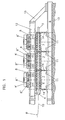
- FIG. 1 illustrates a side view of a strand guide according to the invention according to a first embodiment.
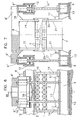
- Fig. 2 shows a detail of Fig. 1 on an enlarged scale, partially in section
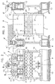
- Fig. 3 is a sectional view taken along the line III-III of Fig. 2.
- Figures 4, 6, 8, 10 and 12 respectively show side views of FIG 2 for different embodiments
- FIGS. 5, 7, 9, 11 and 13 are sectional views according to FIG. 3 for the embodiments shown in FIGS. 4 to 12, and the like. between the lines V-V, VII-VII, IX-IX, XI-XI and XIII-XIII.
- FIG. 14 shows a detail of a further embodiment in a partially sectioned side view according to FIG. 2.
- FIG. 15 shows in the illustration of FIG. 6 a modified embodiment.
- Fig. 1 shows the strand guide in the straight area, but this may also extend in the bow area of a continuous casting.
- the support rollers 6 are each rotatably mounted to a plurality of support frames 7 and 8.
- the respectively the bow outer or lower support rollers 6 receiving support frame 7 (hereinafter referred to as “first” support frame 7) are independent of the upper or inner bow support rollers 6 supporting support frame 8, hereinafter referred to as “second” support frame 8 denotes, on the side of the support frame 7 arranged first longitudinal members 9, which extend in the longitudinal direction 10 of the strand guide, u.zw. over several support frame 7 away, attached via brackets 11.
- the upper and second support frames 8 are also attached to extending in the longitudinal extent 10 of the strand guide second side rails 12, which extend approximately equidistant from the first side rails 9.
- the second longitudinal members 12 are supported on the first longitudinal members 9, which are mounted on the foundation 13, via connecting means 14, which are advantageously designed as tie rods - for receiving the ferrostatic pressure - are formed.
- These tie rods 14 may be designed as flexural rods, which allow different longitudinal expansion of the first longitudinal member 9 with respect to the second longitudinal members 12 compensate in a very simple manner.
- the longitudinal members 9, 12 may be screwed or welded to the connecting means 14; However, it is also possible to make the one of a lower and upper side members 9, 12 and the connecting means 14 formed, acting as a disk construction in one piece.
- the lower side members 9 may also be part of a foundation construction.
- Second support frame 8 Essential for the easy removal and installation of the second support frame 8 is that these are supported from above on the second side members 12, for which purpose the second support frame 8 with the second side members 12 superior side extensions 8 'are provided, on which either hydraulic cylinder sixteenth attack directly or rely on stool 8 ", which in turn are supported on hydraulic cylinders 16.
- first and second side members 9, 12 are connected via an element 15 for mutual fixation of their position.
- This element 15 receives between the first and second longitudinal members acting shear forces and is formed in the illustrated embodiment as directed approximately 45 ° support.
- the first and the second longitudinal members 9 and 12 form with the connecting means 14 each supported on the foundation 13 foundation frame, between which a Zunderkanal extends below, which also serves for the discharge of the cooling water, which is used for cooling the strand 3.
- the upper and second support frames 8 are movable via four hydraulic cylinders 16 on the second longitudinal members 12 supported, wherein the arrangement of the four hydraulic cylinders 16 is made such that when viewed from above they are at the vertices of the approximately rectangular in plan view of the second support frame 8.
- the support of the hydraulic cylinder 16 and the piston rods 17 with the second longitudinal beams 12 and the support frame 8 or stools 8 "via spherical plain bearings, so that it is possible to set a wedge-shaped casting gap.
- the upper and second support frames 8 are guided approximately perpendicular to the longitudinal extension 10 of the strand guide guideways 18 by means of sliding elements 19, such as sliding blocks, wherein shown in FIG. 2, the guideways 18 to the second Side members and the sliding blocks 19 are arranged on the stools 8 '';
- the guideways 18 could also be provided on the support frame 8.
- the guideways 18 are provided according to a preferred embodiment of the intermediate frame 12 '.
- the support frame 7 and 8 can be easily attached to the support frame 7 and 8dehuntabdeckungen 20 form a cooling chamber, so that only the support rollers are inside the same, whereas the hydraulic cylinder 16 and the side members 9, 12 outside the same lie.
- Thedeschabdeckungen 20 extend between the support frame 7 and 8, u.zw. left and right of the outside support cheeks 21 of the lower and upper support frame 7 and 8th
- a first media supply 22 for the lower or first support frame 7 leads over the lower side members 9 to these, and a second media supply 23 for the supply of cooling water or pressure medium to the hydraulic cylinders 16 via the stool 8 "to the upper second support frame eighth wherein the mounted on the support frame 8 Lines when placing the support frame 8 on the stool 8 "are automatically connected to the lines 23, for example by so-called manifold connections.
- a displacement measurement is carried out via the hydraulic cylinders 16, and thus a measurement of the casting gap directly in the cylinders, i.
- This displacement measurement is integrated in the hydraulic cylinders 16.
- the casting gap can be adjusted with G confusedickenbeilagen 25, which are provided between the upper and second support frame 8 and the second longitudinal members 12.
- bending springs 26 are used, which extend with their main direction in the longitudinal direction of the second longitudinal members. These bending springs 26 are formed as leaf spring packets. They are connected on the one hand to the second longitudinal members 12 and on the other hand to the second support frame 8.
- the hydraulic cylinders 16 are attached to the second support frame 8 and have in this embodiment, piston rods 17 which are designed as bending rods which pass through the second longitudinal members 12 with play and the ends of which are rigidly fixed to the lower and first longitudinal members 9.
- piston rods 17 which are designed as bending rods which pass through the second longitudinal members 12 with play and the ends of which are rigidly fixed to the lower and first longitudinal members 9.
- displacement sensors 27 are provided laterally of the strand guide tracks 1 and 2, which are provided on projections of the support frames 7 and 8 and directed against one another.
- the G hassledickenbeilagen 25 may be adjustable in height for the purpose of setting different G intelligentken or exchanged for other G intelligentkenbeilagen 25 with different height.
- FIGs. 12 and 13 An advantageous embodiment is further shown in Figs. 12 and 13, according to which not only the second support frame 8 are supported on the second longitudinal members 12 via hydraulic cylinders 16, but also the first support frame 7 on the first side members 9.
- the first side members 9 arranged on support columns 30 at a distance 31 from the foundation 13 and supported relative to this.
- All of the above-described embodiments of the bearing or guiding of the second support segments 8 on the second longitudinal members 12 can also be used for supporting and guiding the first support frame 7 on the first longitudinal members 9, so that a substantially symmetrical to the strand guide means plane, illustrated by the line 10, formed strand guide is formed.
- To adjust the G fauxspaltes displacement sensors 27 between the first and second support frame 7 and 8 and in addition between the first support frame 7 and the first side rails 9 are provided in this embodiment.
- This variant has the advantage that both the first and the second support frame 7 and 8 can be changed independently and independently of the longitudinal members 9 and 12 and the adjusting mechanisms.
- the hydraulic cylinders 16 are supported on a module 32 having the guideways 18 for the second support frame 8, which module 32 is inserted into the second side members 12 and attached to them with a quick-release connection.
- the Quick release connection is in this case formed by half-rings 33, which are equipped with wedge surfaces which engage counter-wedge surfaces of the module 32.
- the module 32 is formed by the intermediate frame 12 ', the pressure medium cylinders 16 and the stool 8 ".
- the construction according to the invention has numerous advantages over the known constructions, such as the simple possibility of changing the support frame 8 and according to FIGS. 12 and 13 and the support frame 7 without major alterations, excellent accessibility from the side, a simpledehuntkapselung, and further offers the possibility to perform an automatic casting thickness adjustment with position measurement.
- Another advantage is the fact that when changing a support frame 7 or 8, the hydraulic and electrical systems do not have to be decoupled, since when changing a support frame 7 or 8, the hydraulic cylinder 16 and possibly Wegmeßimplantation 27 can remain in the system.
- Fig. 15 shows an embodiment of a strand guide analogous to the representation of Fig. 6, but in contrast to the Au Installationsform of FIG. 6 between two adjacent formed by the support frame 7 and 8 elements independent of these support frame 7 and 8 module 34 for receiving a pair of rollers driven rollers 35 is installed.
- This module 34 is formed by a lower cross member 36 and an upper cross member 37, the lower cross member 36 at the lower, i. first side member 9 and upper cross member 37 on the upper side member, i. are attached to the second longitudinal member 12.
- the upper driven roller 35 of the pair of rollers can be raised and lowered by means of pressure medium cylinder 38 to be employed to different strand formats or to be pressed against the surface of the strand can.
- the advantage of this embodiment is the fact that a change of the support frame 7 and 8 can be done independently of the driven rollers 35, whereby such a change is less time consuming, especially since driven rollers require a high switching time expenditure u.z. because of the drive shafts to be decoupled.
- Such decoupling of the propeller shafts according to this embodiment must be done only when a driven roller itself must be replaced and not for a change of non-driven rollers.
- Fig. 15 further shows force measuring devices 39, e.g. DehnmeßstMail, to the piston 17 of the hydraulic cylinder 16
- force measuring devices 39 e.g. DehnmeßstMail
Landscapes
- Engineering & Computer Science (AREA)
- Mechanical Engineering (AREA)
- Continuous Casting (AREA)
- Escalators And Moving Walkways (AREA)
Claims (29)
- Guidage de chaîne pour une installation de moulage de chaîne, comprenant deux pistes d'appui (1, 2) droites et/ou courbées, disposées de manière opposée l'une par rapport à l'autre, supportant une chaîne (3) sur des côtés (4, 5) opposés et équipées d'éléments d'appui (6), tels que des rouleaux d'appui (6), les éléments d'appui (6) respectivement d'une des pistes d'appui (1, 2) étant disposés par deux ou plus sur des cadres d'appui (7, 8) qui sont appuyés ensemble contre un cadre de fondations (9, 12, 14) en appui contre les fondations, ce cadre de fondations (9, 12, 14) présentant deux premiers supports longitudinaux (9) situés latéralement par rapport à une première piste d'appui (1) inférieure ou arquée vers l'extérieur et s'étendant dans la direction longitudinale (10) de cette première piste d'appui (1) et deux autres deuxièmes supports longitudinaux (12) situés latéralement par rapport à la deuxième piste d'appui (2) supérieure ou arquée vers l'intérieur opposée à la première piste d'appui (1) et s'étendant dans la direction longitudinale (10) de la deuxième piste d'appui (2), caractérisé en ce que- les deuxièmes supports longitudinaux (12) sont respectivement reliés fixement à un premier support longitudinal (9) situé du même côté que les pistes d'appui (1, 2) par l'intermédiaire de moyens de liaison (14) disposés à distance et sont appuyés contre les fondations (13) par l'intermédiaire des premiers supports longitudinaux (9),- les cadres d'appui (7) de la première piste d'appui (1) sont reliés par l'intermédiaire de moyens de réglage (16, 17) aux premiers supports longitudinaux (9) indépendamment des moyens de liaison (14) des supports longitudinaux (9, 12) et les cadres d'appui (8) de la deuxième piste d'appui (2) sont reliés par l'intermédiaire de moyens de réglage (16, 17) aux premiers ou deuxièmes supports longitudinaux (9, 12), et bien entendu également indépendamment des moyens de liaison (14) des supports longitudinaux (9, 12), les cadres d'appui (8) de la deuxième piste d'appui (2) pouvant être enlevés des deuxièmes supports longitudinaux (12) vers le haut et/ou l'intérieur de l'arc indépendamment des cadres d'appui (7) de la première piste d'appui (1).
- Guidage de chaîne selon la revendication 1, caractérisé en ce que les cadres d'appui (7) de la première piste d'appui (1) sont reliés par l'intermédiaire de moyens de réglage (16) aux premiers supports longitudinaux (9) et bien entendu indépendamment des moyens de liaison (14) des supports longitudinaux (9, 12).
- Guidage de chaîne selon la revendication 1 ou 2, caractérisé en ce que les moyens de liaison (14) des supports longitudinaux (9, 12) sont réalisés sous la forme de tirants (14).
- Guidage de chaîne selon la revendication 3, caractérisé en ce que les tirants (14) sont réalisés sous la forme de barres de flexion (14) et les premiers et deuxièmes supports longitudinaux (9, 12) sont fixés l'un contre l'autre à un endroit de leur extension longitudinale par l'intermédiaire d'un élément (15) recevant des poussées générées entre les supports longitudinaux (9, 12).
- Guidage de chaîne selon une ou plusieurs des revendications 1 à 4, caractérisé en ce que les premiers et/ou deuxièmes supports longitudinaux (9, 12) sont munis de pistes de guidage (18) s'étendant à peu près perpendiculairement à leur extension longitudinale pour recevoir des éléments coulissants (19) prévus contre les cadres d'appui (7, 8) de la première ou deuxième piste d'appui (1, 2).
- Guidage de chaîne selon la revendication 5, caractérisé en ce que les pistes de guidage (18) sont réalisées sous la forme de modules (32) pouvant être montés dans les supports longitudinaux (9, 12) et fixés contre ces supports longitudinaux.
- Guidage de chaîne selon une ou plusieurs des revendications 1 à 6, caractérisé en ce que des cadres d'appui (7, 8) de la première et/ou deuxième piste d'appui (1, 2) sont reliés aux premiers ou deuxièmes supports longitudinaux (9, 12) par l'intermédiaire de ressorts de flexion (26), les ressorts de flexion (26) s'étendant dans leur direction principale dans la direction longitudinale (10) des supports longitudinaux (9, 12).
- Guidage de chaîne selon une ou plusieurs des revendications 1 à 6, caractérisé en ce que des cadres d'appui (7, 8) de la première et/ou deuxième piste d'appui (1, 2) sont reliés aux premiers ou deuxièmes supports longitudinaux (9, 12) par l'intermédiaire d'organes de direction.
- Guidage de chaîne selon une ou plusieurs des revendications 1 à 8, caractérisé en ce que des cadres d'appui (7, 8) de la première et/ou deuxième piste d'appui (1, 2) sont appuyés contre les premiers ou deuxièmes supports longitudinaux (9, 12) au moyen de vérins formant des moyens de pression (16), en particulier de vérins hydrauliques (16).
- Guidage de chaîne selon une ou plusieurs des revendications 1 à 9, caractérisé en ce que les cadres d'appui (7, 8) de la première et/ou deuxième piste d'appui (1, 2) sont appuyés contre les vérins formant des moyens de pression par l'intermédiaire d'un tabouret (8").
- Guidage de chaîne selon la revendication 10, caractérisé en ce que des conduites d'alimentation en milieux (23) conduisent au tabouret (8'') et débouchent via ceux-ci dans des raccords des cadres d'appui (7, 8).
- Guidage de chaîne selon une ou plusieurs des revendications 9 à 11, caractérisé en ce que les vérins formant des moyens de pression (16) sont chargés, dans le fonctionnement en moulage, dans la direction des supports longitudinaux (9, 12) respectivement opposés et en ce que, entre les cadres d'appui (7, 8) de la première et deuxième piste d'appui (1, 2), des pièces d'insertion pour l'épaisseur du moulage (25) sont prévues l'une par rapport à l'autre en vue de la fixation de la position des cadres d'appui (7, 8).
- Guidage de chaîne selon la revendication 12, caractérisé en ce que des pièces d'insertion pour l'épaisseur du moulage (25) sont prévues entre des barres d'appui (29) disposées latéralement contre les premiers cadres d'appui (7) et contre les cadres d'appui (8) de la deuxième piste d'appui (2).
- Guidage de chaîne selon une ou plusieurs des revendications 1 à 13, caractérisé en ce que les cadres d'appui (7, 8) de la première et/ou deuxième piste d'appui (1, 2) ne sont appuyés contre des supports longitudinaux (9, 12) respectivement correspondants qu'à l'aide d'un seul vérin formant moyen de pression à chaque fois (16).
- Guidage de chaîne selon une ou plusieurs des revendications 1 à 13, caractérisé en ce les cadres d'appui (7, 8) de la première et/ou deuxième piste d'appui (1, 2) sont appuyés contre les premiers ou deuxièmes supports longitudinaux (9, 12) par l'intermédiaire de quatre vérins formant des moyens de pression (16) disposés respectivement contre les zones en coin apparaissant dans le plan des cadres d'appui.
- Guidage de chaîne selon une ou plusieurs des revendications 1 à 15, caractérisé en ce que, pour déterminer la position des cadres d'appui (7, 8) de la première et/ou deuxième piste d'appui (1, 2) par rapport aux cadres d'appui (7, 8) de la piste d'appui (1, 2) respectivement opposée entre les premiers et deuxièmes cadres d'appui (7, 8), des capteurs de course (27) sont prévus, de préférence contre des prolongements (28) disposés latéralement par rapport aux cadres d'appui (7, 8) et orientés l'un par rapport à l'autre.
- Guidage de chaîne selon une ou plusieurs des revendications 9 à 16, caractérisé en ce que les vérins hydrauliques (16) prévus entre les premiers et/ou deuxièmes supports longitudinaux (9, 12) et les cadres d'appui (7, 8) de la première et/ou deuxième piste d'appui (1, 2) sont équipés d'un réglage pour régler une position prédéterminée des cadres d'appui (7, 8) l'un par rapport à l'autre et/ou par rapport aux supports longitudinaux (9, 12).
- Guidage de chaîne selon la revendication 17, caractérisé en ce que les vérins hydrauliques (16) sont couplés à des capteurs de course (27).
- Guidage de chaîne selon une ou plusieurs des revendications 1 à 18, caractérisé en ce que des parois de chambre froide (20) sont directement prévues contre les cadres d'appui (7, 8) de la première et deuxième piste d'appui.
- Guidage de chaîne selon une ou plusieurs des revendications 9 à 19, caractérisé en ce que les vérins hydrauliques (16) prévus pour l'appui des cadres d'appui (7, 8) contre les supports longitudinaux (9, 12) sont fixés au moyen d'une liaison à desserrage rapide aux supports longitudinaux (9, 12) et/ou aux cadres d'appui (7, 8) ou, dans le cas où un tabouret (8'') est prévu, à celui-ci, de préférence au moyen d'un assemblage par clavettes.
- Guidage de chaîne selon une ou plusieurs des revendications 1 à 20, caractérisé en ce que, des capteurs de course (27) sont prévus aussi bien entre les premiers supports longitudinaux (9) et les cadres d'appui (7) de la première piste d'appui (1) qu'entre les cadres d'appui (7, 8) de la première et deuxième piste d'appui (1, 2).
- Guidage de chaîne selon une ou plusieurs des revendications 1 à 21, caractérisé en ce que les cadres d'appui (7, 8) de la première et/ou deuxième piste d'appui (1, 2) sont munis de prolongements latéraux (8') dépassant côté extérieur des supports longitudinaux (9, 12) correspondants, avec lesquels les cadres d'appui (7, 8) sont appuyés contre les supports longitudinaux (9, 12) correspondants, directement ou par l'intermédiaire de moyens de réglage (16) ou, dans le cas où un tabouret (8") est prévu, contre celui-ci.
- Guidage de chaîne selon une ou plusieurs des revendications 1 à 22, caractérisé en ce que les supports longitudinaux (9, 12) sont réalisés d'une seule pièce avec les moyens de liaison (14).
- Guidage de chaîne selon une ou plusieurs des revendications 1 à 23, caractérisé en ce que, entre des cadres d'appui adjacents (7, 8), un module propre (34) est prévu pour la réception d'au moins une paire de rouleaux, composée de rouleaux (35) entraînés et disposés de manière opposée l'un par rapport à l'autre.
- Guidage de chaîne selon la revendication 24, caractérisé en ce que le module (34) présente deux supports transversaux (36, 37), l'un des supports transversaux (36) étant appuyé contre le premier support longitudinal (9) et l'autre support transversal (37) contre le deuxième support longitudinal (12) et en ce qu'au moins un rouleau entraîné (35) est appuyé, soit directement, soit indirectement, contre chacun des supports transversaux (36, 37).
- Guidage de chaîne selon la revendication 25, caractérisé en ce qu'un rouleau entraîné (35) est appuyé contre le support transversal (37) par l'intermédiaire d'un dispositif de déplacement (38), tel qu'un vérin formant moyen de pression (38).
- Guidage de chaîne selon une ou plusieurs des revendications 9 à 26, caractérisé en ce que les moyens de réglage (16, 17) sont équipés de dispositifs de mesure de force (39), de préférence de bandes de mesure de dilatation.
- Procédé de réglage de la position de cadres d'appui adjacents (7, 8) l'un par rapport à l'autre dans une installation selon une ou plusieurs des revendications 1 à 27, caractérisé en ce que la position relative de cadres d'appui adjacents (7, 8) est mesurée, comme par exemple par les capteurs de course ou par un appareil de mesure de fente de moulage ou par des évaluations de la pression des moyens de réglage (16) pendant un fonctionnement à l'essai et/ou pendant le fonctionnement en moulage, et en ce que, dans le cas où des écarts de la piste de la fente de moulage composée des pistes d'appui (1, 2) sont déterminés, la position de consigne des cadres d'appui (7, 8) est corrigée à l'aide des moyens de réglage.
- Procédé de détermination du point de solidification d'une chaîne moulée dans une installation selon une ou plusieurs des revendications 1 à 27, caractérisé en ce que des mesures de la dilatation sont réalisés sur les moyens de liaison (14) des supports longitudinaux (9, 12).
Applications Claiming Priority (3)
| Application Number | Priority Date | Filing Date | Title |
|---|---|---|---|
| AT9732000A AT408853B (de) | 2000-06-02 | 2000-06-02 | Strangführung für eine stranggiessanlage |
| AT973002000 | 2000-06-02 | ||
| PCT/AT2001/000182 WO2001091942A1 (fr) | 2000-06-02 | 2001-06-01 | Guidage de brin d'une installation de coulee continue |
Publications (2)
| Publication Number | Publication Date |
|---|---|
| EP1286796A1 EP1286796A1 (fr) | 2003-03-05 |
| EP1286796B1 true EP1286796B1 (fr) | 2007-01-03 |
Family
ID=3683723
Family Applications (1)
| Application Number | Title | Priority Date | Filing Date |
|---|---|---|---|
| EP01940010A Expired - Lifetime EP1286796B1 (fr) | 2000-06-02 | 2001-06-01 | Guidage de brin d'une installation de coulee continue |
Country Status (4)
| Country | Link |
|---|---|
| EP (1) | EP1286796B1 (fr) |
| AT (1) | AT408853B (fr) |
| DE (1) | DE50111806D1 (fr) |
| WO (1) | WO2001091942A1 (fr) |
Cited By (1)
| Publication number | Priority date | Publication date | Assignee | Title |
|---|---|---|---|---|
| WO2009100813A1 (fr) | 2008-02-14 | 2009-08-20 | Sms Siemag Ag | Dispositif de guidage de barre, notamment pour une installation de coulée continue de brame d'acier |
Families Citing this family (2)
| Publication number | Priority date | Publication date | Assignee | Title |
|---|---|---|---|---|
| DE102011088127A1 (de) * | 2011-06-07 | 2012-12-13 | Sms Siemag Ag | Strangführungssegment einer Strangführung einer Stranggießanlage und Verfahren zum Betreiben eines Strangführungssegments |
| CN115418471B (zh) * | 2022-09-19 | 2023-08-29 | 祝桥金属材料启东有限公司 | 一种钢带热处理装置 |
Family Cites Families (8)
| Publication number | Priority date | Publication date | Assignee | Title |
|---|---|---|---|---|
| CH495800A (de) * | 1969-05-20 | 1970-09-15 | Concast Ag | Auszieh- und Richtvorrichtung für Stranggiezzanlagen mit gekrümmter Strangführung |
| BE787511A (fr) * | 1971-08-16 | 1973-02-12 | Uss Eng & Consult | Procede et appareil pour redresser des pieces coulees en continu |
| AT337386B (de) * | 1975-09-03 | 1977-06-27 | Voest Ag | Rollengerust fur stranggiessanlagen |
| AT368049B (de) * | 1979-11-28 | 1982-08-25 | Voest Alpine Ag | Einrichtung an einem stuetz- und fuehrungsgeruest fuer eine stranggiessanlage |
| DE3303386A1 (de) * | 1983-02-02 | 1984-08-09 | SMS Schloemann-Siemag AG, 4000 Düsseldorf | Stuetzfuehrung in einer stranggiessanlage |
| DE3829549A1 (de) * | 1988-08-31 | 1990-03-08 | Voest Alpine Ind Anlagen | Strangfuehrungsgeruest fuer eine stranggiessanlage |
| DE4306853C2 (de) * | 1993-02-26 | 1996-03-21 | Mannesmann Ag | Strangführungsgerüst |
| DE19811651A1 (de) * | 1998-03-18 | 1999-09-23 | Schloemann Siemag Ag | Stützführung für den Gießstrang einer Stranggießanlage |
-
2000
- 2000-06-02 AT AT9732000A patent/AT408853B/de not_active IP Right Cessation
-
2001
- 2001-06-01 EP EP01940010A patent/EP1286796B1/fr not_active Expired - Lifetime
- 2001-06-01 WO PCT/AT2001/000182 patent/WO2001091942A1/fr not_active Ceased
- 2001-06-01 DE DE50111806T patent/DE50111806D1/de not_active Expired - Fee Related
Cited By (2)
| Publication number | Priority date | Publication date | Assignee | Title |
|---|---|---|---|---|
| WO2009100813A1 (fr) | 2008-02-14 | 2009-08-20 | Sms Siemag Ag | Dispositif de guidage de barre, notamment pour une installation de coulée continue de brame d'acier |
| DE102008009136A1 (de) | 2008-02-14 | 2009-10-15 | Sms Siemag Aktiengesellschaft | Strangführung, insbesondere für eine Stahlbrammen-Stranggießanlage |
Also Published As
| Publication number | Publication date |
|---|---|
| DE50111806D1 (de) | 2007-02-15 |
| EP1286796A1 (fr) | 2003-03-05 |
| WO2001091942A1 (fr) | 2001-12-06 |
| AT408853B (de) | 2002-03-25 |
| ATA9732000A (de) | 2001-08-15 |
Similar Documents
| Publication | Publication Date | Title |
|---|---|---|
| EP0551584B1 (fr) | Dispositif de fermeture de moule pour presses à injection | |
| EP0005760A1 (fr) | Machine pour le redressage de tôles et de bandes | |
| WO2008058595A1 (fr) | Dispositif de changement de cylindre avec dispositif de réglage de cale | |
| EP0236905B1 (fr) | Dispositif pour appliquer une pression superficielle sur des pièces à travailler en mouvement de translation | |
| DE19511113A1 (de) | Strangführung einer Stranggießanlage für Dünnbrammen | |
| DE2644096C2 (de) | Stütz- und Führungsbogen für Gußstränge, insbesondere für Brammengußstränge | |
| DE69511651T2 (de) | Walzanlage | |
| EP1121573A1 (fr) | Bascule a wagons | |
| EP0802837A1 (fr) | Presse horizontale d'extrusion pour metal | |
| DE4408099B4 (de) | Meß- und Steuereinrichtung zur Stahlbandführung entlang der Längsachse einer kontinuierlich arbeitenden Presse | |
| EP0857522B1 (fr) | Train de laminage | |
| DE3901961C2 (fr) | ||
| DE4444941C2 (de) | Stranggießkokille | |
| DE69608937T2 (de) | Richtmaschine mit parallelem zylinder | |
| DE1809260A1 (de) | Walzwerk | |
| EP0222732B1 (fr) | Guide de barre | |
| AT408853B (de) | Strangführung für eine stranggiessanlage | |
| EP0010728B1 (fr) | Installation de coulée continue avec une lingotière oscillante | |
| EP0184025A2 (fr) | Dispositif de guidage sur les bandes de coulée d'une lingotière de coulée continue à bande double | |
| EP0679454A1 (fr) | Machine de dressage pour dresser des tôles et des bandes | |
| DE3829549C2 (fr) | ||
| DE3238939C2 (de) | Vorrichtung zum Zuführen einer Schmelze, insbesondere von Aluminium, zu einer horizontalen Walzen-Stranggießanlage | |
| DE2729938B2 (de) | Doppelbandpresse zum Herstellen von Preßplatten | |
| DE1908879B2 (de) | Klemmwalzenanordnung für eine vertikale Strangführung | |
| DE102020206297A1 (de) | Zwischengerüstführung an einem Vertikalwalzgerüst einer Walzstraße sowie Verfahren zur Führung des Walzgutes unter Verwendung der Zwischengerüstführung |
Legal Events
| Date | Code | Title | Description |
|---|---|---|---|
| PUAI | Public reference made under article 153(3) epc to a published international application that has entered the european phase |
Free format text: ORIGINAL CODE: 0009012 |
|
| 17P | Request for examination filed |
Effective date: 20021128 |
|
| AK | Designated contracting states |
Designated state(s): AT BE CH CY DE DK ES FI FR GB GR IE IT LI LU MC NL PT SE TR Kind code of ref document: A1 Designated state(s): AT BE CH CY DE DK ES FI FR GB GR IE IT LI LU MC NL PT SE TR |
|
| RBV | Designated contracting states (corrected) |
Designated state(s): AT BE DE IT |
|
| GRAP | Despatch of communication of intention to grant a patent |
Free format text: ORIGINAL CODE: EPIDOSNIGR1 |
|
| GRAS | Grant fee paid |
Free format text: ORIGINAL CODE: EPIDOSNIGR3 |
|
| GRAA | (expected) grant |
Free format text: ORIGINAL CODE: 0009210 |
|
| AK | Designated contracting states |
Kind code of ref document: B1 Designated state(s): DE IT |
|
| REF | Corresponds to: |
Ref document number: 50111806 Country of ref document: DE Date of ref document: 20070215 Kind code of ref document: P |
|
| PLBE | No opposition filed within time limit |
Free format text: ORIGINAL CODE: 0009261 |
|
| STAA | Information on the status of an ep patent application or granted ep patent |
Free format text: STATUS: NO OPPOSITION FILED WITHIN TIME LIMIT |
|
| 26N | No opposition filed |
Effective date: 20071005 |
|
| PGFP | Annual fee paid to national office [announced via postgrant information from national office to epo] |
Ref country code: IT Payment date: 20090624 Year of fee payment: 9 |
|
| PGFP | Annual fee paid to national office [announced via postgrant information from national office to epo] |
Ref country code: DE Payment date: 20090821 Year of fee payment: 9 |
|
| PG25 | Lapsed in a contracting state [announced via postgrant information from national office to epo] |
Ref country code: IT Free format text: LAPSE BECAUSE OF NON-PAYMENT OF DUE FEES Effective date: 20100601 |
|
| PG25 | Lapsed in a contracting state [announced via postgrant information from national office to epo] |
Ref country code: DE Free format text: LAPSE BECAUSE OF NON-PAYMENT OF DUE FEES Effective date: 20110101 |
|
| PG25 | Lapsed in a contracting state [announced via postgrant information from national office to epo] |
Ref country code: AT Free format text: LAPSE BECAUSE OF NON-PAYMENT OF DUE FEES Effective date: 20070103 |
|
| PG25 | Lapsed in a contracting state [announced via postgrant information from national office to epo] |
Ref country code: BE Free format text: LAPSE BECAUSE OF NON-PAYMENT OF DUE FEES Effective date: 20070630 |