EP1286889B1 - Vorrichtung zum verpacken von gegenständen wie topfpflanzen in einem schlauch - Google Patents
Vorrichtung zum verpacken von gegenständen wie topfpflanzen in einem schlauch Download PDFInfo
- Publication number
- EP1286889B1 EP1286889B1 EP01943963A EP01943963A EP1286889B1 EP 1286889 B1 EP1286889 B1 EP 1286889B1 EP 01943963 A EP01943963 A EP 01943963A EP 01943963 A EP01943963 A EP 01943963A EP 1286889 B1 EP1286889 B1 EP 1286889B1
- Authority
- EP
- European Patent Office
- Prior art keywords
- sleeve
- sleeves
- sheet
- objects
- holding member
- Prior art date
- Legal status (The legal status is an assumption and is not a legal conclusion. Google has not performed a legal analysis and makes no representation as to the accuracy of the status listed.)
- Expired - Lifetime
Links
Images



Classifications
-
- B—PERFORMING OPERATIONS; TRANSPORTING
- B65—CONVEYING; PACKING; STORING; HANDLING THIN OR FILAMENTARY MATERIAL
- B65B—MACHINES, APPARATUS OR DEVICES FOR, OR METHODS OF, PACKAGING ARTICLES OR MATERIALS; UNPACKING
- B65B25/00—Packaging other articles presenting special problems
- B65B25/02—Packaging agricultural or horticultural products
- B65B25/026—Packaging flower pots
-
- B—PERFORMING OPERATIONS; TRANSPORTING
- B65—CONVEYING; PACKING; STORING; HANDLING THIN OR FILAMENTARY MATERIAL
- B65B—MACHINES, APPARATUS OR DEVICES FOR, OR METHODS OF, PACKAGING ARTICLES OR MATERIALS; UNPACKING
- B65B43/00—Forming, feeding, opening or setting-up containers or receptacles in association with packaging
- B65B43/12—Feeding flexible bags or carton blanks in flat or collapsed state; Feeding flat bags connected to form a series or chain
- B65B43/123—Feeding flat bags connected to form a series or chain
Definitions
- the invention relates to an apparatus for packing objects, such as pot plants, into sleeves, wherein the sleeves are formed by a first sheet and a second sheet which are connected to each other at their edges, with the exception of the upper edge.
- an apparatus comprises a holding member for holding the sleeves, and an opening member for moving the first sheet and the second sheet apart at least on the upper side.
- the apparatus further comprises a filling member for picking up the objects for packing and placing the objects into the opened sleeve.
- the holding member is adapted to hold the sleeve on a strip releasably connected to the first sheet of the sleeve.
- the holding member comprises a carrier which extends through at least two holes arranged in the strips, which strips are connected to the sleeves forming part of the group.
- the holding member is adapted for connection to each of the strips of a group of sleeves, the sheets of which extend mutually parallel.
- the holding member comprises guides which are adapted to successively guide the ends of the carriers to an engaging position in which the opening member can engage the sleeves.
- Groups of sleeves where each group of sleeves is connected to one carrier, can hereby be moved to the engaging position.
- the holding member comprise a controllable blocking for blocking the route along the guides or to the pick-up position.
- the blocking is coupled to an unloading device for removing a carrier from the engaging position when the blocking is released.
- the empty carrier is hereby removed automatically when a new, full carrier is supplied.
- the opening member is provided with at least one suction cup, movable in a direction transversely of the surface of the sleeve, for engaging the second sheet of a sleeve situated in the engaging position and causing the second sheet to move away from the first sheet of the sleeve.
- This construction ensures opening of the sleeves on the upper side. This is a difficult problem, since the two sheets from which the sleeve is assembled are usually pulled toward each other by static electricity and it is thus difficult to move them apart. By providing at least one suction cup it becomes possible to obtain a good attachment to the second sheet, so that the second sheet can be moved away from the first sheet.
- the opening member comprises a downward directed blow nozzle placed above the holding member.
- the sleeve is then opened further by a pin which forms part of the opening member and which is movable with a directional component transversely of the surface of the sleeve for engaging the opened sleeve on the inside and further opening the sleeve. It is after all of great importance that the opening obtained on the upper side of the sleeve is sufficiently large for passage of the object; folding and creasing of the sleeve are hereby prevented.
- the pin is adapted to perform a movement with a vertical component to enable movement of the pin into the opened sleeve.
- An attractive embodiment further results when at least two pins are placed on the slide.
- the opening member comprises at least one other pin which is only movable in vertical direction. This measure provides the possibility of holding the sleeve open prior to moving the object into the sleeve.
- the filling member comprises a gripper adapted to pick up the objects which is connected to the movable arm, with which the gripper is movable from a pick-up position to an unloading position above the opened sleeve, and the gripper is adapted to release the object in the unloading position.
- This construction operates in particularly attractive manner when use is made of a sleeve as claimed in claim 19 comprising two sheets and an object for packing in the sleeve, which is characterized in that one sheet of the sleeve is connected to a strip by means of a releasable connection, wherein the connection is, dimensioned to break when the holding member is moved upward relative to the opening member.
- the apparatus is dimensioned for the packing of pot plants into sleeves.
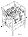
- Figure 1 shows a sleeving apparatus 1 which comprises a frame 2.
- a feed conveyor belt 3 which extends into the frame from outside, as well as a conveyor belt 4 which extends from the frame to a position outside the frame.
- two holding members 5 for holding sleeves, as well as two opening members 6 for opening the sleeves, and a double-action filling member 7 for picking up pot plants 8 supplied via feed conveyor belt 3, placing the pot plants above the opened sleeves and releasing the pot plants, so that they come to lie in the sleeve, the sleeve breaks off from the strip attached thereto and comes to lie on the outfeed conveyor belt 4.
- Filling member 7 is formed by a carriage 10 which can travel along rails 9 arranged horizontally in frame 2.
- Carriage 10 can move in horizontal direction along the rails.
- Extending downward from the carriage are four rods 11 on which a slide 12 is mounted.
- By means of a drive integrated into the carriage it is possible to move the rods 11 upward, as well as the slide 12 connected fixedly thereto. It is thus possible to move slide 12 in horizontal and vertical direction.
- Mounted on slide 12 are two pick-up elements 13 which are each adapted to pick up the pot of a pot plant 8.
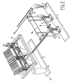
- two holding members 5 are further arranged in the frame for holding the sleeves into which the pot plants must be placed.
- the holding member is formed essentially by an auxiliary frame 14. On this auxiliary frame are mounted two brackets 15 which are adapted to carry a rod 16.
- a stack of sleeves 17 is connected to a rod 16 in that each of the sleeves 17 is fixed to a strip 18.
- Strip 18 is separated from each of the sleeves by means of a perforation.
- perforations 19 through which the rod extends. It is thus possible for a number of sleeves to be fastened to one rod 16.
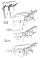
- brackets 15 When a rod 16 is present in brackets 15, brackets 15 function as holding device. The rods remain resting thereon and are enclosed inside bracket 15 and a frame part 20. It will be apparent that it is important for the machine to operate at the highest possible speed. For this purpose a rod, when the sleeves 17 fastened thereto are all filled and removed from the rod, must be discharged quickly and replaced by a new, filled rod. Use is made for this purpose of a supply rail 21 leading to the position of the bracket. Supply rail 21 extends obliquely and is provided with a groove in which a large number of rods 16 can be placed.
- a block 22 to which bracket 18 is fixed is slid backward in the direction of arrow 23 as shown in figure 4a.
- the space between frame part 20 and bracket 15 is hereby left clear, so that rod 16 can drop downward.
- the bracket further clears the lower outlet of supply rail 21, so that the subsequent rod present in supply rail 21 can drop downward onto bracket 15.
- the block 22 moves again in the direction of arrow 24 of figure 4b, so that the rod is enclosed and the situation of figure 4c is obtained, and the filled rod can have its sleeves removed.
- the sleeve-opening member comprises a first slide 25 which is movable in horizontal direction inside the auxiliary frame.
- first slide 25 Connected to first slide 25 are two auxiliary carriers 26 which are movable in horizontal direction relative to slide 25 by means of a linear drive element, for instance a pneumatic cylinder 27.
- a linear drive element for instance a pneumatic cylinder 27.
- suction cups 28 On each of the carriers 26 are placed two suction cups 28 which are connected to a vacuum pump not shown in the drawing. Using suction cups 28 one sheet of the sleeves consisting of two sheets can be pulled away from the other sheet.
- a combination can be made of the movement of the linear drive element 27 and the drive of the first slide 25, so that suction cups 28 are moved toward the relevant sheet, the suction cups are energized and the sleeves are pulled up.
- Use can otherwise be made herein of a blowing means, arranged above the sleeve-opening member, for directing an airflow downward; this contributes toward further opening of the sleeve.
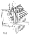
- second slide 29 which second slide is provided with pins, as best shown in figure 6.
- second slide 29 is movable in horizontal direction along the auxiliary frame 14, while on the second frame at the position of each of the bags there are arranged two pins 30 which can enlarge the opening formed by suction cups 28 on the upper side of the sleeve by causing the second slide to move further outward.
- Pins 30 are manufactured from resilient but strong material. This facilitates the removal of the sleeve when the objects drop into the sleeve. It is also possible to manufacture the pins from rigid material and to connect them to the frame in resilient manner.
- the second slide 29 is furthermore movable in vertical direction by means of linear drive elements 31.
- Figure 7 further shows that inside the space between brackets 15 and frame parts 20 the rods 18 can be moved upward from the sleeves by linear drive elements mounted on the auxiliary frame. It is hereby possible to move the whole of the sleeve package some distance upward, so that it is possible to tear the opened sleeve away from the carrier. This is otherwise also possible when the pot plants are caused to fall into the opened sleeve; this can involve such a development of force that the sleeve tears away from the strip. An automatic severing action is hereby obtained. It is however recommended to separate the severing operation from the filling operation; this results in a better controllability.
Landscapes
- Engineering & Computer Science (AREA)
- Mechanical Engineering (AREA)
- Life Sciences & Earth Sciences (AREA)
- Agronomy & Crop Science (AREA)
- Supplying Of Containers To The Packaging Station (AREA)
- Cultivation Receptacles Or Flower-Pots, Or Pots For Seedlings (AREA)
- Packaging Of Special Articles (AREA)
- Catching Or Destruction (AREA)
- Packging For Living Organisms, Food Or Medicinal Products That Are Sensitive To Environmental Conditiond (AREA)
- Auxiliary Apparatuses For Manual Packaging Operations (AREA)
- Packages (AREA)
Claims (19)
- Vorrichtung (1) zum Verpacken von Gegenständen wie Topfpflanzen (8) in Hüllen (17), wobei die Hüllen durch einen ersten Bogen und einen zweiten Bogen gebildet werden, die miteinander mit Ausnahme der Oberkanten an den Kanten verbunden sind, wobei die Vorrichtung (1) umfasst:- ein Halteelement (5) zum Halten der Hüllen (17); und- ein Öffnungselement (6) zum Auseinanderbewegen des ersten Bogens und des zweiten Bogens zumindest an der Oberseite,gekennzeichnet durch
ein Einfüllelement (7) zur Aufnahme der zu verpackenden Gegenstände und Hineinstellen der Gegenstände in die geöffnete Hülle (17),
wobei das Halteelement (5) ausgebildet ist, um die Hülle (17) auf einem Streifen zu halten, der lösbar mit dem ersten Bogen der Hülle (17) verbunden ist und einen Träger aufweist, der sich durch mindestens zwei in den Streifen angeordneten Löcher erstreckt, wobei die mit den Hüllen (17) verbundenen Streifen Teil einer Gruppe bilden. - Vorrichtung gemäß Anspruch 1, dadurch gekennzeichnet, dass das Halteelement (5) zur Verbindung mit jedem der Streifen einer Gruppe von Hüllen (17) ausgebildet ist, wobei die Bögen der Hüllen beidseitig parallel verlaufen.
- Vorrichtung gemäß Anspruch 1, dadurch gekennzeichnet, dass das Halteelement (5) Führungen umfasst, die ausgebildet sind, um die Enden der Träger nacheinander in eine Eingriffsposition zu führen, in der das Öffnungselement (6) in die Hüllen (17) eingreifen kann.
- Vorrichtung gemäß Anspruch 3, dadurch gekennzeichnet, dass das Halteelement (5) ein steuerbare Sperre zum Sperren des Wegs entlang der Führungen bis zur Aufnahmeposition umfasst.
- Vorrichtung gemäß Anspruch 4, dadurch gekennzeichnet, dass die Sperre mit einer Entladeeinrichtung verbunden ist, um einen Träger aus der Eingriffsposition zu entfernen, wenn die Sperre aufgehoben wird.
- Vorrichtung gemäß einem der vorhergehenden Ansprüche, dadurch gekennzeichnet, dass das Öffnungselement (6) zumindest einen Sauger umfasst, der in einer Richtung quer zur Oberfläche einer Hülle (17) bewegbar ist, um in den zweiten Bogen einer in der Eingriffsposition befindlichen Hülle (17) einzugreifen, und um den zweiten Bogen vom ersten Bogen der Hülle (17) wegzuziehen.
- Vorrichtung gemäß einem der vorhergehenden Ansprüche, dadurch gekennzeichnet, dass das Öffnungselement (6) eine nach unten gerichtete Luftdüse aufweist, die über dem Halteelement (6) angeordnet ist.
- Vorrichtung gemäß Anspruch 6 oder 7, dadurch gekennzeichnet, dass das Öffnungselement (6) zumindest einen Stift umfasst, der mit einer Richtungskomponente quer zur Oberfläche der Hülle (17) bewegbar ist, um in die geöffneten Hülle (17) in der Innenseite einzugreifen und die Hülle (17) weiter zu öffnen.
- Vorrichtung gemäß Anspruch 8, dadurch gekennzeichnet, dass zumindest ein Stift zur Durchführung einer Bewegung mit einer vertikalen Komponente ausgebildet ist, um die Bewegung des Stifts in die geöffneten Hülle (17) zu ermöglichen.
- Vorrichtung gemäß einem der Ansprüche 6 bis 9, dadurch gekennzeichnet, dass zumindest ein Sauger auf einem ersten Schlitten angeordnet ist, wobei der mindestens eine Stift auf einem zweiten Schlitten angeordnet ist und beide Schlitten entlang desselben Wegs bewegbar sind.
- Vorrichtung gemäß Anspruch 10, dadurch gekennzeichnet, dass zumindest zwei Stifte auf dem Schlitten angeordnet sind.
- Vorrichtung gemäß einem der Ansprüche 6 bis 11, dadurch gekennzeichnet, dass das Öffnungselement (6) zumindest einen weiteren Stift umfasst, der nur in vertikaler Richtung bewegbar ist.
- Vorrichtung gemäß einem der Ansprüche 8 bis 12, dadurch gekennzeichnet, dass die Stifte aus elastischem Material gefertigt sind.
- Vorrichtung gemäß einem der vorhergehenden Ansprüche, dadurch gekennzeichnet, dass das Einfüllelement (7) einen Greifer enthält, der zur Aufnahme der Gegenstände ausgebildet und mit einem bewegbaren Arm verbunden ist, mit dem der Greifer von einer Aufnahmeposition zu einer Entladeposition über der geöffneten Hülle (17) bewegbar ist, und dass der Greifer ausgebildet ist, um den Gegenstand in der Entladeposition freizugeben.
- Vorrichtung gemäß Anspruch 14, dadurch gekennzeichnet, dass die Entladeposition sich in einem gewissen Abstand über der Oberseite der geöffneten Hülle (17) befindet.
- Vorrichtung gemäß Anspruch 14 oder 15, dadurch gekennzeichnet, dass ein Transportband zu einer Aufnahmeposition führt und dass unter der Aufnahmeposition ein Auslauftransportband zum Abladen der in einer Hülle (17) verpackten Gegenstände angeordnet ist.
- Vorrichtung gemäß einem der vorhergehenden Ansprüche, dadurch gekennzeichnet, dass das Halteelement (5) relativ zum Öffnungselement (6) nach oben bewegbar ist.
- Vorrichtung gemäß einem der vorhergehenden Ansprüche, dadurch gekennzeichnet, dass die Vorrichtung (1) zum Verpacken von Topfpflanzen (8) in Hüllen (17) ausgelegt ist.
- Verwenden einer Hülle in einer Vorrichtung (1) zum Verpacken von Gegenständen wie Topfpflanzen (8) gemäß einem der vorhergehenden Ansprüche, wobei die Hülle (17) durch einen ersten Bogen und einen zweiten Bogen gebildet wird, die miteinander mit Ausnahme der Oberkanten an den Kanten verbunden sind, dadurch gekennzeichnet, dass einer der ersten und zweiten Bögen der Hülle mittels einer lösbaren Verbindung mit einem Streifen verbunden ist.
Applications Claiming Priority (3)
| Application Number | Priority Date | Filing Date | Title |
|---|---|---|---|
| NL1015409 | 2000-06-09 | ||
| NL1015409A NL1015409C2 (nl) | 2000-06-09 | 2000-06-09 | Inrichting voor het in hoezen verpakken van voorwerpen, zoals potplanten. |
| PCT/NL2001/000441 WO2001094207A1 (en) | 2000-06-09 | 2001-06-11 | Apparatus for packing objects like pot plants into sleeves |
Publications (2)
| Publication Number | Publication Date |
|---|---|
| EP1286889A1 EP1286889A1 (de) | 2003-03-05 |
| EP1286889B1 true EP1286889B1 (de) | 2007-12-26 |
Family
ID=19771520
Family Applications (1)
| Application Number | Title | Priority Date | Filing Date |
|---|---|---|---|
| EP01943963A Expired - Lifetime EP1286889B1 (de) | 2000-06-09 | 2001-06-11 | Vorrichtung zum verpacken von gegenständen wie topfpflanzen in einem schlauch |
Country Status (6)
| Country | Link |
|---|---|
| EP (1) | EP1286889B1 (de) |
| AT (1) | ATE382017T1 (de) |
| AU (1) | AU2001266422A1 (de) |
| DE (1) | DE60132083D1 (de) |
| NL (1) | NL1015409C2 (de) |
| WO (1) | WO2001094207A1 (de) |
Families Citing this family (5)
| Publication number | Priority date | Publication date | Assignee | Title |
|---|---|---|---|---|
| US6931818B2 (en) * | 2003-02-14 | 2005-08-23 | Createch | Method and apparatus for packing flower bouquets |
| NL1026297C2 (nl) * | 2004-05-28 | 2005-12-09 | Terra Internat B V | Inrichting en werkwijze voor het aanbrengen van een hoes om een potplant. |
| NL1031378C2 (nl) * | 2006-03-15 | 2007-09-18 | Edward Keijzer | Werkwijze en inrichting voor het aanbrengen van een hoes om een potplant. |
| US8709332B2 (en) | 2011-07-20 | 2014-04-29 | Nike, Inc. | Thermoforming sheet loading apparatus and method |
| EP3138667B1 (de) * | 2015-09-03 | 2018-12-26 | Spisa Holding AB | Robotische vorrichtung zur umhüllung von topfpflanzen und verfahren zur umhüllung von topfpflanzen mit der robotischen umhüllungsvorrichtung |
Family Cites Families (3)
| Publication number | Priority date | Publication date | Assignee | Title |
|---|---|---|---|---|
| US3360901A (en) * | 1965-01-21 | 1968-01-02 | Gallo Joseph | Packaging device for positioning a tubular type envelope over potted plants and similar articles |
| CH632965A5 (de) * | 1976-10-29 | 1982-11-15 | Bernd Muenchinger | Vorrichtung zum herstellen und fuellen von verpackungsmitteln fuer waren und gegenstaende. |
| DE2808550A1 (de) * | 1978-02-28 | 1979-08-30 | Wilhelm Scherz | Foerdereinrichtung fuer das tragband eines tuetenbandes |
-
2000
- 2000-06-09 NL NL1015409A patent/NL1015409C2/nl not_active IP Right Cessation
-
2001
- 2001-06-11 AT AT01943963T patent/ATE382017T1/de not_active IP Right Cessation
- 2001-06-11 EP EP01943963A patent/EP1286889B1/de not_active Expired - Lifetime
- 2001-06-11 DE DE60132083T patent/DE60132083D1/de not_active Expired - Lifetime
- 2001-06-11 AU AU2001266422A patent/AU2001266422A1/en not_active Abandoned
- 2001-06-11 WO PCT/NL2001/000441 patent/WO2001094207A1/en not_active Ceased
Also Published As
| Publication number | Publication date |
|---|---|
| NL1015409C2 (nl) | 2001-12-28 |
| DE60132083D1 (de) | 2008-02-07 |
| EP1286889A1 (de) | 2003-03-05 |
| ATE382017T1 (de) | 2008-01-15 |
| NL1015409A1 (nl) | 2001-12-12 |
| AU2001266422A1 (en) | 2001-12-17 |
| WO2001094207A1 (en) | 2001-12-13 |
Similar Documents
| Publication | Publication Date | Title |
|---|---|---|
| US5024042A (en) | Bag filling and closing apparatus | |
| US6601707B2 (en) | Wicketed and wicket-less bags and method of filling the bags | |
| CN211845146U (zh) | 一种自动装箱机的隔板装置 | |
| US9272804B2 (en) | Bundle unwrapping machine | |
| JPH0259054B2 (de) | ||
| US11352160B2 (en) | Apparatus for emptying bags | |
| EP0461084B1 (de) | Vorrichtung zum Herstellen von Kartons aus flachen hülsenartigen Zuschnitten | |
| CA1053627A (en) | Automatic wicketted bag loader | |
| JPH0834413A (ja) | フォイルチューブ包装体の切断兼積重ね装置 | |
| US3330093A (en) | Bag loading mechanisms and machines | |
| CA2780376C (en) | Device and method for forming stacks of bags | |
| EP1286889A1 (de) | Vorrichtung zum verpacken von gegenständen wie topfpflanzen in einem schlauch | |
| US6453646B1 (en) | Method for producing bags | |
| US3412522A (en) | Mechanism for successively feeding bags to a bag loading machine | |
| US20120012440A1 (en) | Negative-pressure conveyor | |
| KR20190027331A (ko) | 삼각 샌드위치용 포장기 및 삼각 샌드위치의 포장 방법 | |
| JPH03500746A (ja) | 紙、厚紙又は同様な材料から成るシートをダイカットしかつ分離する装置 | |
| CN109534033B (zh) | 用于拾取坯料样品的装置、用于修整片材形元件的机器以及拾取坯料的方法 | |
| US20110000171A1 (en) | Method and apparatus for debanding a compressible bundle | |
| CN117326140B (zh) | 一种成对注塑件的分拣机 | |
| JP2006510555A6 (ja) | 真空包装機および装填システム | |
| JP2006510555A (ja) | 真空包装機および装填システム | |
| US3074326A (en) | Apparatus for expanding a carton and inserting same into a conveyer bucket | |
| JP7432613B2 (ja) | パッケージング製造機用のシート状要素を受け取るためのステーション及び方法 | |
| CN111532513B (zh) | 立式包装机 |
Legal Events
| Date | Code | Title | Description |
|---|---|---|---|
| PUAI | Public reference made under article 153(3) epc to a published international application that has entered the european phase |
Free format text: ORIGINAL CODE: 0009012 |
|
| AK | Designated contracting states |
Designated state(s): AT BE CH CY DE DK ES FI FR GB GR IE IT LI LU MC NL PT SE TR Kind code of ref document: A1 Designated state(s): AT BE CH CY DE DK ES FI FR GB GR IE IT LI LU MC NL PT SE TR |
|
| AX | Request for extension of the european patent |
Extension state: AL LT LV MK RO SI |
|
| 17P | Request for examination filed |
Effective date: 20021209 |
|
| RAP1 | Party data changed (applicant data changed or rights of an application transferred) |
Owner name: VISSER 'S-GRAVENDEEL HOLDING B.V. |
|
| 17Q | First examination report despatched |
Effective date: 20060313 |
|
| GRAP | Despatch of communication of intention to grant a patent |
Free format text: ORIGINAL CODE: EPIDOSNIGR1 |
|
| RIN1 | Information on inventor provided before grant (corrected) |
Inventor name: BONTENBAL, JAKOBUS |
|
| GRAS | Grant fee paid |
Free format text: ORIGINAL CODE: EPIDOSNIGR3 |
|
| GRAA | (expected) grant |
Free format text: ORIGINAL CODE: 0009210 |
|
| AK | Designated contracting states |
Kind code of ref document: B1 Designated state(s): AT BE CH CY DE DK ES FI FR GB GR IE IT LI LU MC NL PT SE TR |
|
| REG | Reference to a national code |
Ref country code: GB Ref legal event code: FG4D |
|
| REG | Reference to a national code |
Ref country code: IE Ref legal event code: FG4D |
|
| REG | Reference to a national code |
Ref country code: CH Ref legal event code: EP |
|
| REF | Corresponds to: |
Ref document number: 60132083 Country of ref document: DE Date of ref document: 20080207 Kind code of ref document: P |
|
| PG25 | Lapsed in a contracting state [announced via postgrant information from national office to epo] |
Ref country code: LI Free format text: LAPSE BECAUSE OF FAILURE TO SUBMIT A TRANSLATION OF THE DESCRIPTION OR TO PAY THE FEE WITHIN THE PRESCRIBED TIME-LIMIT Effective date: 20071226 Ref country code: CH Free format text: LAPSE BECAUSE OF FAILURE TO SUBMIT A TRANSLATION OF THE DESCRIPTION OR TO PAY THE FEE WITHIN THE PRESCRIBED TIME-LIMIT Effective date: 20071226 Ref country code: SE Free format text: LAPSE BECAUSE OF FAILURE TO SUBMIT A TRANSLATION OF THE DESCRIPTION OR TO PAY THE FEE WITHIN THE PRESCRIBED TIME-LIMIT Effective date: 20080326 |
|
| PG25 | Lapsed in a contracting state [announced via postgrant information from national office to epo] |
Ref country code: FI Free format text: LAPSE BECAUSE OF FAILURE TO SUBMIT A TRANSLATION OF THE DESCRIPTION OR TO PAY THE FEE WITHIN THE PRESCRIBED TIME-LIMIT Effective date: 20071226 |
|
| REG | Reference to a national code |
Ref country code: CH Ref legal event code: PL |
|
| PG25 | Lapsed in a contracting state [announced via postgrant information from national office to epo] |
Ref country code: AT Free format text: LAPSE BECAUSE OF FAILURE TO SUBMIT A TRANSLATION OF THE DESCRIPTION OR TO PAY THE FEE WITHIN THE PRESCRIBED TIME-LIMIT Effective date: 20071226 |
|
| PG25 | Lapsed in a contracting state [announced via postgrant information from national office to epo] |
Ref country code: ES Free format text: LAPSE BECAUSE OF FAILURE TO SUBMIT A TRANSLATION OF THE DESCRIPTION OR TO PAY THE FEE WITHIN THE PRESCRIBED TIME-LIMIT Effective date: 20080406 |
|
| PG25 | Lapsed in a contracting state [announced via postgrant information from national office to epo] |
Ref country code: BE Free format text: LAPSE BECAUSE OF FAILURE TO SUBMIT A TRANSLATION OF THE DESCRIPTION OR TO PAY THE FEE WITHIN THE PRESCRIBED TIME-LIMIT Effective date: 20071226 |
|
| PG25 | Lapsed in a contracting state [announced via postgrant information from national office to epo] |
Ref country code: PT Free format text: LAPSE BECAUSE OF FAILURE TO SUBMIT A TRANSLATION OF THE DESCRIPTION OR TO PAY THE FEE WITHIN THE PRESCRIBED TIME-LIMIT Effective date: 20080526 |
|
| EN | Fr: translation not filed | ||
| PG25 | Lapsed in a contracting state [announced via postgrant information from national office to epo] |
Ref country code: DK Free format text: LAPSE BECAUSE OF FAILURE TO SUBMIT A TRANSLATION OF THE DESCRIPTION OR TO PAY THE FEE WITHIN THE PRESCRIBED TIME-LIMIT Effective date: 20071226 Ref country code: DE Free format text: LAPSE BECAUSE OF FAILURE TO SUBMIT A TRANSLATION OF THE DESCRIPTION OR TO PAY THE FEE WITHIN THE PRESCRIBED TIME-LIMIT Effective date: 20080327 |
|
| PLBE | No opposition filed within time limit |
Free format text: ORIGINAL CODE: 0009261 |
|
| STAA | Information on the status of an ep patent application or granted ep patent |
Free format text: STATUS: NO OPPOSITION FILED WITHIN TIME LIMIT |
|
| 26N | No opposition filed |
Effective date: 20080929 |
|
| PG25 | Lapsed in a contracting state [announced via postgrant information from national office to epo] |
Ref country code: GR Free format text: LAPSE BECAUSE OF FAILURE TO SUBMIT A TRANSLATION OF THE DESCRIPTION OR TO PAY THE FEE WITHIN THE PRESCRIBED TIME-LIMIT Effective date: 20080327 Ref country code: MC Free format text: LAPSE BECAUSE OF NON-PAYMENT OF DUE FEES Effective date: 20080630 |
|
| GBPC | Gb: european patent ceased through non-payment of renewal fee |
Effective date: 20080611 |
|
| PG25 | Lapsed in a contracting state [announced via postgrant information from national office to epo] |
Ref country code: FR Free format text: LAPSE BECAUSE OF FAILURE TO SUBMIT A TRANSLATION OF THE DESCRIPTION OR TO PAY THE FEE WITHIN THE PRESCRIBED TIME-LIMIT Effective date: 20081017 Ref country code: IE Free format text: LAPSE BECAUSE OF NON-PAYMENT OF DUE FEES Effective date: 20080611 |
|
| PG25 | Lapsed in a contracting state [announced via postgrant information from national office to epo] |
Ref country code: GB Free format text: LAPSE BECAUSE OF NON-PAYMENT OF DUE FEES Effective date: 20080611 |
|
| PG25 | Lapsed in a contracting state [announced via postgrant information from national office to epo] |
Ref country code: CY Free format text: LAPSE BECAUSE OF FAILURE TO SUBMIT A TRANSLATION OF THE DESCRIPTION OR TO PAY THE FEE WITHIN THE PRESCRIBED TIME-LIMIT Effective date: 20071226 |
|
| PG25 | Lapsed in a contracting state [announced via postgrant information from national office to epo] |
Ref country code: LU Free format text: LAPSE BECAUSE OF NON-PAYMENT OF DUE FEES Effective date: 20080611 |
|
| PG25 | Lapsed in a contracting state [announced via postgrant information from national office to epo] |
Ref country code: TR Free format text: LAPSE BECAUSE OF FAILURE TO SUBMIT A TRANSLATION OF THE DESCRIPTION OR TO PAY THE FEE WITHIN THE PRESCRIBED TIME-LIMIT Effective date: 20071226 |
|
| PG25 | Lapsed in a contracting state [announced via postgrant information from national office to epo] |
Ref country code: IT Free format text: LAPSE BECAUSE OF NON-PAYMENT OF DUE FEES Effective date: 20080630 |
|
| PGFP | Annual fee paid to national office [announced via postgrant information from national office to epo] |
Ref country code: NL Payment date: 20130630 Year of fee payment: 13 |
|
| PG25 | Lapsed in a contracting state [announced via postgrant information from national office to epo] |
Ref country code: NL Free format text: LAPSE BECAUSE OF NON-PAYMENT OF DUE FEES Effective date: 20150101 |