EP1287276B1 - Differenz druckregler - Google Patents
Differenz druckregler Download PDFInfo
- Publication number
- EP1287276B1 EP1287276B1 EP01920044A EP01920044A EP1287276B1 EP 1287276 B1 EP1287276 B1 EP 1287276B1 EP 01920044 A EP01920044 A EP 01920044A EP 01920044 A EP01920044 A EP 01920044A EP 1287276 B1 EP1287276 B1 EP 1287276B1
- Authority
- EP
- European Patent Office
- Prior art keywords
- groove
- designed
- house
- pressure regulator
- differential pressure
- Prior art date
- Legal status (The legal status is an assumption and is not a legal conclusion. Google has not performed a legal analysis and makes no representation as to the accuracy of the status listed.)
- Expired - Lifetime
Links
- 239000012528 membrane Substances 0.000 claims abstract description 25
- 239000011324 bead Substances 0.000 claims abstract description 21
- 230000008878 coupling Effects 0.000 claims abstract description 19
- 238000010168 coupling process Methods 0.000 claims abstract description 19
- 238000005859 coupling reaction Methods 0.000 claims abstract description 19
- 238000007789 sealing Methods 0.000 claims abstract description 10
- 238000003780 insertion Methods 0.000 claims abstract description 8
- 230000037431 insertion Effects 0.000 claims abstract description 8
- 230000006835 compression Effects 0.000 claims abstract description 6
- 238000007906 compression Methods 0.000 claims abstract description 6
- 238000005192 partition Methods 0.000 claims abstract description 4
- 230000000717 retained effect Effects 0.000 claims description 3
- 230000005489 elastic deformation Effects 0.000 claims description 2
- 239000002184 metal Substances 0.000 claims description 2
- 230000000750 progressive effect Effects 0.000 claims description 2
- 230000000087 stabilizing effect Effects 0.000 claims description 2
- 238000006073 displacement reaction Methods 0.000 claims 1
- 230000007812 deficiency Effects 0.000 description 2
- 239000000463 material Substances 0.000 description 2
- 230000001105 regulatory effect Effects 0.000 description 2
- 230000011664 signaling Effects 0.000 description 2
- 238000006243 chemical reaction Methods 0.000 description 1
- 238000010276 construction Methods 0.000 description 1
- 238000001816 cooling Methods 0.000 description 1
- 230000000694 effects Effects 0.000 description 1
- 238000010438 heat treatment Methods 0.000 description 1
- 230000001771 impaired effect Effects 0.000 description 1
- 238000009434 installation Methods 0.000 description 1
- 238000004519 manufacturing process Methods 0.000 description 1
- 238000000465 moulding Methods 0.000 description 1
- 230000002441 reversible effect Effects 0.000 description 1
- XLYOFNOQVPJJNP-UHFFFAOYSA-N water Substances O XLYOFNOQVPJJNP-UHFFFAOYSA-N 0.000 description 1
Images

Classifications
-
- G—PHYSICS
- G05—CONTROLLING; REGULATING
- G05D—SYSTEMS FOR CONTROLLING OR REGULATING NON-ELECTRIC VARIABLES
- G05D16/00—Control of fluid pressure
- G05D16/04—Control of fluid pressure without auxiliary power
- G05D16/06—Control of fluid pressure without auxiliary power the sensing element being a flexible membrane, yielding to pressure, e.g. diaphragm, bellows, capsule
- G05D16/063—Control of fluid pressure without auxiliary power the sensing element being a flexible membrane, yielding to pressure, e.g. diaphragm, bellows, capsule the sensing element being a membrane
- G05D16/0644—Control of fluid pressure without auxiliary power the sensing element being a flexible membrane, yielding to pressure, e.g. diaphragm, bellows, capsule the sensing element being a membrane the membrane acting directly on the obturator
- G05D16/0655—Control of fluid pressure without auxiliary power the sensing element being a flexible membrane, yielding to pressure, e.g. diaphragm, bellows, capsule the sensing element being a membrane the membrane acting directly on the obturator using one spring-loaded membrane
- G05D16/0661—Control of fluid pressure without auxiliary power the sensing element being a flexible membrane, yielding to pressure, e.g. diaphragm, bellows, capsule the sensing element being a membrane the membrane acting directly on the obturator using one spring-loaded membrane characterised by the loading mechanisms of the membrane
-
- G—PHYSICS
- G05—CONTROLLING; REGULATING
- G05D—SYSTEMS FOR CONTROLLING OR REGULATING NON-ELECTRIC VARIABLES
- G05D16/00—Control of fluid pressure
- G05D16/028—Controlling a pressure difference
Definitions
- the present invention relates to a differential pressure regulator of the type set forth in the preamble of claim 1.
- Such regulators are used e.g. to regulate the pressure drop over the contents in a heating or cooling system and are usually built into a water return conduit.
- the regulator must be disassembled, a plurality of individual loose parts being obtained, and such loose parts are not always the parts, which are subjected to e.g. wear and tear to a great extent. Consequently, the subsequent mounting will be more lengthy and time-consuming.
- During an assembly and disassembly it is often necessary to initially remove all the attachments, since these in their attached condition are likely to be subjected to improper stresses.
- Various measuring and discharge possibilities often do not exist.
- the adjustment requirement of a required function of the regulator often is less expedient. A change a preadjusted values often is carried out by non-authorized persons.
- a deairation of the regulators can be a difficult problem and furthermore special tools may be required for this purpose and also a certain precise mounting position may be required.
- a cut-off function is lacking sometimes or it is not easily accessible or it is complicated, e.g. requiring special tools.
- the adjustment of the regulator and consequently its performance can be changed, e.g. in such a way, that the stroke/flow volume of the valve is restricted.
- the reliability and the life of the regulators can be unsatisfactory.
- the problem may be, that it is difficult to quickly, simply and reliably measure a functional failure and then in a suitable way take care of it. Problems with generated noise may arise.
- a well balanced reaction capacity often does not exist. Also, the material consumption and too large dimensions and proportions respectively sometimes can be troublesome factors.
- the object of the present invention is to counteract and as far as possible eliminate the above-mentioned drawbacks and to develop a differential pressure regulator, which is improved as regards separate details as well as particularly combined details.
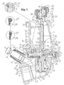
- the differential pressure regulator 1 is shown in its entirety. It comprises two main parts, namely a lower part 2 and an upper part 3.
- the lower part comprises an inlet 4 and an outlet 5.
- the flow direction may in particular cases be reverse, the inlet being an outlet and the outlet being an inlet.
- They are separated from each other by means of a partition 6, which accommodates a seat 7, against which a valve body 8 is designed to act, which constitutes or is connected to the lower end of valve spindle 9.
- the lower part comprises also discharge and/or measuring connection means 11 of a type known per se, which houses an circumferential flange 10, which projects into the inlet.
- These means are suitably protected by a cover 12, made of rubber or a plastic material, which by means of an in a suitable way shaped first holder 13 is fastened to said lower part and which by means of a second holder 14 secures a cap 15.
- a cup 16 which preferably has a plane bottom 17 with a relatively large diameter and a shorter circular cylindrical wall 18, which surrounds said bottom and has an extension, designed as a step 19 all around, which is connected to the free end and is used as stop means for a flange 20 at coupling end 21 of upper part 3.
- a groove 22 all around, designed for a lock ring 23.
- a shorter axial, annular projection 24 projects axially into cup 16 at a distance from wall 18, the lower end of the projection being designed as a radially outwardly directed holding flange 25.
- Flanges 20and 25 include between themselves and wall 24 a groove 26 all around, designed to house an annular bead 27, which constitutes the outer end of a membrane 28, which is extended somewhat and abuts wall 18 towards bottom 17 and then via a soft rounded fold 29, while retreating from wall 18 and bottom 17, becomes a plane, central part 30 at a level roughly between bead 27 and bottom 17 in a closed regulating position.
- the outer diameter of holding flange 25 is somewhat smaller than the inner diameter of the cup, at least regarding this level, the membrane being fastened between wall 18 and flange 25.
- Upper part 3 comprises a house 31, which e.g. is die-cast and can be connected to the lower part by means of said coupling end 21, and in the coupling movement per se there is no relative torsion between the lower part and the upper part despite the fact, that the upper part and the lower part can be rotated limitlessly in relation to each other.
- the advantage is obtained, that the upper part quickly and without problems steplessly can occupy an arbitrary rotated position in relation to the lower part in order to meet any requirements as to positional alignment between the lower part and the upper part, and that possibly existing connections do not have to be removed , when the upper part and the lower part are joined to each other and disassembled from each other respectively. Also, the connections are not subjected to inappropriate stresses.
- House 31 suitably has a rotational symmetrical cross-section and preferably comprises a central portion 32, designed as a truncated cover in an axial direction, the lower part of which coincides with or is adjacent coupling end 21.
- This cone-shaped portion houses spindle 9 as well as a cone-shaped compression spring 33, which surrounds the spindle and the upper narrow end of which is retained by a support 34, which with a central hole 35 having an inner thread is threaded on the spindle, which is provided with an outer thread, and which with two projections 36 on mutually diametrically opposite sides is guided in axial guiding channels 37 in house 31.
- These grooves are made in parts 38 of the house, which are designed in a corresponding way. In this manner a torsion of the spindle will result in, that support 34, which is not rotatable , will move in an axial direction in house 31 and thereby compress spring 33 and let it expand respectively.
- One of house parts 38 is e.g. provided with an upper connection 39 and a lower connection 40, which are designed for partly signaling circuit connection and partly deairation.
- the connection which depending on the assembly position of the regulator ends up in an upper position, is used for deairation, whereas the other connection is used for signaling circuit connection.
- the connection or connections, which possibly are not used, can be provided with a plug 85.
- Spindle 9 extends with its outer end into the area within the free end of house 31, which end receives a bushing 42, the end of which, which projects out of the house, is surrounded by a hand wheel 41.
- the hand wheel is rotatably mounted on the bushing and is, with an inner thread 43, threaded on an outer thread 44 on house 31.
- bushing 42 is not rotable but axially moveable in a relative way on the outer spindle end, which is not rotation symmetrical, but e.g. hexagonal, and is inserted into an in a corresponding way designed blind hole 80 in the bushing, which is rotated by means of an opening 45, made in the free bushing end, e.g. for a hexagon spanner.
- Bushing 42 is inserted from within into a circumferential flange 46 in the house, a flange 47 all around and mounted on the remote bushing end projecting into a groove 48, which surrounds the inner end of the opening of the circumferential flange, in house 31 and thus being used as an insertion stop.
- the bushing is surrounded by an O-ring 50, which is inserted into a groove 49 all around and seals against the opening of the circumferential flange , and keeps , close to its free outer end by means of a locking ring 51, the hand wheel 41 in place.
- the spindle is surrounded by a groove 52 and a locking ring 53, inserted in the groove, which is designed to prevent, that support 36, already at a minor prestressing of spring 33, abuts said gable and in this way limits or eliminates the movement path of the valve body.
- a locking ring 53 enters into an extension 54 all around in the support adjacent to its inner thread, the locking ring in this way being efficiently locked along about 300° of the cross-section area of the locking ring and it will be practically impossible for the locking ring to leave its position, when the rotation of the spindle is continued.
- Said groove 52 must be deeper than the depth of the outer thread in a radial direction in order to avoid a deformation of the thread and a loosening of the locking ring.
- Valve body 8 is at its end , which is exposed to seat 7, provided with a groove 56 all around, which suitably is roughly semicircular in its cross-section and has an engaging lip 57. Subsequent to an insertion of an O-ring 58 into the groove the radially projecting lip is pressed downwards into an axial direction, the O-ring being squeezed and projecting with only a portion of its axial extension through groove 56, which in the same direction roughly is reduced by halves. In this way the O-ring is efficiently kept in place and is extended at the same time in a radial direction in order to optimally seal against seat 7 in a closing position.
- valve body is surrounded by a groove 59, in which however the groove wall, which faces the seat, suitably is somewhat withdrawn in order to pass a stop 60 in bore 61 of lower part 2 for the valve body and to more readily fill up the more narrow part 62 of this bore close to the seat.
- the groove wall which is turned away from the seat, fills on the other hand with a slip fit up the upper bore part, which has a large diameter.
- an O-ring 63 which is inserted in groove 59, abuts step 60 and accomplishes in this way a satisfactory sealing between the inlet and the outlet.
- Said O-ring 63 has such small dimensions in relation to the rest of said bore part, that the least possible friction is obtained between these parts.
- a sealing effect is aimed at and is obtained only, when O-ring 63 abuts said step with a certain elastic deformation, which results in the sealing function.
- valve body and the spindle constitute a homogenous unit.
- Membrane 28 is supported with its plane portion 30 by a membrane plate 67, also plane, and suitably, with its intermediate part 68, provided with holes, with which it is slipped onto the spindle, is forced onto and around the center, with its holes, of the plate in order to make it abut the lower side of the plate having a lower, annular termination 69, which softly is allowed to abut the side of the valve body close to the cup.
- the membrane and the plate suitably are vulcanized together in order to obtain an easily mountable unit, which preferably is slidably mounted on the spindle.
- Spring 33 is supported with its wide lower end by a spring holder 70, which suitably comprises a stamped and bent metal plate having a central hole 71 with a diameter, which is much larger than the diameter of the spindle, which projects through said hole, and has holes 72 for a mounting fixture.
- Center 73 of the holder suitably is elevated in order to obtain a lower edge section 74 all around, against which the spring abuts in a self-centering way.
- the edge section is extended outwards in a radial direction in order to form bayonet projections 75, designed to be inserted into house 31 through corresponding recesses 76, circumferentially seen outside and in an axial direction above which the house is provided with a locking groove 77 all around, in which projections 75 are designed to be inserted.
- the locking groove is limited downwards by flange sections 78, which are terminated symmetrically by guiding channels 37, i.e. each guiding channel being centrally arranged in relation to the corresponding flange section.
- Each one of the projections is centrally provided with a downwardly stamped locking lug 79, which snaps into the guiding channel, when the spring holder is turned 90° into its mounting position.
- the extension of the locking groove in the axial direction is sufficiently large in order to initially house the total extension in an axial direction of the projections and the locking lugs, which are somewhat pressed downwards.
- a differential pressure regulator designed in this way functions in the following manner:
- the mounting of the parts of the differential pressure regulator is to begin with simple and reliable.
- the lower part comprises, with the exception of measuring connecting means 11, no movable parts.
- Its coupling end 55 suitably has an angle of inclination of 15° in relation to the axis of flow passage 4,5, whereas circular edge 10 can have an angle of 45° in relation to said axis.
- Other arbitrary angular positions of said parts are of course possible.
- valve body can initially be provided with the two O-rings and be mounted on the spindle in the described manner. Then the membrane plate with its membrane is mounted on the spindle and will be supported by the valve body, subsequent to which spring holder 70 and spring 33 are mounted on the spindle and are secured by screwing support 34 onto the spindle. Support 34 is fastened in its turn by means of locking ring 53.
- the unit which is obtained in this way, is inserted into house 31 and projections 36 are inserted into guiding channels 37 and the free spindle end is pressed into the bushing, whereas bayonet projections 75 are guided through recesses 76, until they end up at the same level as locking groove 77, at which level they are stopped by means of a step 83 in house 31.
- the required axial position has been reached and the unit is rotated 90° in relation to the house, projections 75 being forced into the portion of groove 77, which is limited downwards by flange section 78.
- each one of lugs 79 ends up in a position in front of a guiding channel 37 and is pressed into a lower indent 84, formed therein.
- Holding flange 25 is also important to some extent in this context, because it will force the membrane area to a position inside/below the bead between itself and wall 18, an additional sealing as well as an additional stabilizing of the coupling bond being obtained in this way, which latter is made permanent by mounting locking ring 23 in groove 22. A slight pressure against the free axial end of the bead can be generated in this way, which end thus is compressed and , when it springs back, elastically retains flange 20 against locking ring 23.
- the differential pressure regulator completely assembled in this manner, can now be mounted in a medium conduit, and a signal circuit and measuring equipment respectively can then be connected. In case it is later necessary to disassemble the upper part, it is possible to do this with or without the attachments connected to the regulator, and it is only necessary to remove locking ring 23, and then lift up the complete upper part from the lower part.
- Fig. 1 Two extreme regulating positions are shown in Fig. 1, in which the left part shows a manually obtained closing position.
- the hand wheel has then been completely screwed onto thread 44 and the bushing has thereby been moved as far as possible into house 31.
- the bushing then abuts with its inlet to blind hole 80 against a bevel 86 all around, which terminates the thread on the spindle within this area, and moves the spindle, until the valve body abuts seat 7, lower O-ring accomplishing the sealing against the seat, whereas the upper O-ring abuts against step 60 in order to seal the inlet against the outlet also via bore 61.
- the spring according to the invention often makes such a selection superfluous or expands said area, because it is designed to be partly linear and partly progressive, which can be obtained by means of a non-uniform pitch and/or a non-uniform spring wire diameter design.
- curve-shaped force characteristics are obtained and the length of the spring can be made substantially smaller than the length of a spring with an even pitch and an constant wire diameter.
- Tests with a regulator with a spring designed in this way have shown, that only 75 % of the total ⁇ p-tolerance depends on the spring and that the rest of the percentage, 25 %, includes the mechanical inertias of the regulator construction and this is independent of the ⁇ p-value, which has been selected within the operational area of the product.
- this preadjustment position can be fixed by turning the hand wheel e.g. anti-clockwise, until a distinct stop has been reached. In this position the bushing cannot be rotated using normal forces and consequently the preadjustment has been secured.
- the fixing is obtained by tightening flange 47 against the bottom of groove 48, the friction between these two parts generating the locking force.
Landscapes
- Physics & Mathematics (AREA)
- Fluid Mechanics (AREA)
- General Physics & Mathematics (AREA)
- Engineering & Computer Science (AREA)
- Automation & Control Theory (AREA)
- Control Of Fluid Pressure (AREA)
- Fluid-Pressure Circuits (AREA)
- Safety Valves (AREA)
- Mechanical Treatment Of Semiconductor (AREA)
- Semiconductor Lasers (AREA)
- Steroid Compounds (AREA)
Claims (15)
- Ein Differenzdruckregler (1) der ein Unterteil (2) und ein Oberteil (3) umfasst, das mit besagtem Unterteil mittels einem Ende (21) mit einem Halteflansch (20) verbunden sein kann, wobei das Unterteil mit einem Einlass (4) und einem Auslass (5) sowie einer Trennwand (6) zwischen dem Einlass montiert und der Auslass mit einem Ventilsitz (7) versehen ist, gegen welchen ein Ventilkörper (8) einwirken soll, der an einem Ende einer Ventilspindel (9) montiert wird, die in besagtem Oberteil (3) montiert und in einer Richtung einer vorbelasteten Druckfeder (33) betätigt und von einer Membrane (30) umschlossen ist, die mittels einer Verstärkungsrippe (27) am dazwischen liegenden besagten Oberteil (3) und am besagten Unterteil (2) befestigt ist und die diese Teile gegeneinander abdichtet, wodurch das Kupplungsende (21) des Oberteils (3) oberhalb des Halteflanschs (20) zum Unterteil hin als eine ringförmige Verlängerung (24) gestaltet ist, die in axialer Richtung des Oberteils (3) gerichtet ist, gekennzeichnet dadurch, dass die Verlängerung (24) mit ihrem freien Ende einen radial nach außen gerichteten Halteflansch (25) bildet und eine Nut (26) umgibt, in welche die Verstärkungsrippe (27) der Membrane eingeführt wird, dass der Befestigungsbereich der Membrane (28) vorwiegend axial gerichtet ist, d. h. vorwiegend parallel zur Einsetzrichtung, dass eine Dichtung hergestellt bzw. durch radiales Komprimieren des Verstärkungsrippenbereichs (27) zwischen einer axialen Innenwand (18) des Kupplungsendes (55) des Unterteils und des Nutbodens (26) verstärkt werden soll, dass der Halteflansch (20) auf einen Abschnitt (19) im Kupplungsende des Abschnitts (19) einwirkt, und dass eine Schraubklemme (23) so entworfen ist, um das Oberteil drehbar und fest gegen das Unterteil zu halten.
- Ein Differenzdruckregler nach Anspruch 1, gekennzeichnet dadurch, dass der Ventilkörper bzw. das nahe beim Ventilkörper liegende Spindelende konzentrisch von einer Kappe (16) umgeben sind, welche vorzugsweise einen ebenen Boden (17) mit verhältnismäßig großem Durchmesser hat, wobei dieser Boden von besagter Innenwand (18) umgeben ist, die kürzer und rundzylindrisch ist und als Träger für den Bereich der Membrane nahe der Verstärkungsrippe fungiert, deren Bereich in einer leicht abgerundeten Falte (29) von der Wand (18) und dem Boden (17) entfernt entwickelt wurde, wobei sich besagte Falte zu ein ebenes zentrales Membranteil (30) entwickelt.
- Ein Differenzdruckregler nach Anspruch 2, gekennzeichnet dadurch, dass der Außendurchmesser des Halteflansches (25) etwas kleiner ist als der Innendurchmesser der Kappe, zur Befestigung der Membrane zwischen der Innenwand (18) und dem Halteflansch (25).
- Ein Differenzdruckregler nach Anspruch 1 - 3, gekennzeichnet dadurch, dass das Oberteil (3) z. B. ein Kokillengehäuse (31) umfasst, das mittels besagtem Kupplungsende (21) an das Unterteil gekuppelt werden kann, dass das Gehäuse (31) zweckmäßig nicht rotationssymmetrisch im Querschnitt ist und vorzugsweise ein in axialer Richtung zentrales Teil (32) aufweist, das als Stumpfkegel gestaltet ist, dessen Basisteil mit dem Kupplungsende (21) zusammentrifft oder daran anliegt, dass besagtes kegelförmiges Teil teilweise die Spindel (9) und teilweise besagte Druckfeder (33) aufnimmt, welche die Spindel umgibt und eine kegelförmige Form aufweist, wobei das obere, nahe liegende Federende von einer Stütze (34) zurückgehalten wird, welche mit einem zentralen Loch (35) mit einem Innengewinde auf einer mit Außengewinde versehenen Spindel versehen ist und welche mit zwei Vorsprüngen (36) auf gegenseitig diametral gegenüberliegenden Seiten in axialen Führungskanälen (37) im Gehäuse (31) geführt wird, wobei die Kanäle aus den Gehäuseteilen (38) hergestellt sind, die entsprechend gestaltet sind, wobei eine Rotation der Spindel und eine nicht drehende axiale Bewegung der Stütze (34) im Gehäuse (31) eine Komprimierung bzw. eine Ausdehnung der Feder (33) verursacht.
- Ein Differenzdruckregler nach Anspruch 4, gekennzeichnet dadurch, dass mindestens ein Gehäuseteil (38) mit einer oberen Verbindung (39) und einer unteren Verbindung (40) ausgestattet ist, welche in einer willkürlichen Reihenfolge teilweise für einen Signalleitungsanschluss und teilweise für eine Entlüftung gestaltet werden.
- Ein Differenzdruckregler nach einem beliebigen der Ansprüche 1 - 5, gekennzeichnet dadurch, dass sich die Spindel (9) mit deren äußeren Ende in den Bereich innerhalb des freien Gehäuseabschlusses (31) erstreckt, das eine Buchse (42) trägt, wobei deren aus dem Gehäuse vorstehendes Ende von einem Handrad (41) umgeben ist, sowie dadurch, dass das Handrad drehbar auf der Buchse montiert ist und mit einem Innengewinde (43) auf einem Außengewinde (44) am Gehäuse (31) versehen ist, während die Buchse (42) nicht drehbar sondern axial montiert wird mit einer relativen Verschiebung auf das äußere Ende der Spindel, das nicht rotationssymmetrisch, z. B. sechseckig und in eine Blindbohrung (80) eingeführt, entsprechend in der Buchse ausgestaltet ist, um mittels einer Öffnung (45) im freien Buchsenende gedreht zu werden für z. B. einen Sechskantschlüssel.
- Ein Differenzdruckregler nach Anspruch 6, gekennzeichnet dadurch, dass die Buchse (42) so gestaltet ist, um innerhalb eines Umfangsflansches (46) ins Gehäuse eingeführt zu werden, wobei ein rundum montierter Flansch (47) am äußeren Ende der Buchse in eine Nut (48) hineinragt, die das innere Ende des Umfangsflansches im Gehäuse (31) umgibt und folglich als Einführanschlag dient, sowie dadurch, dass die Buchse von einem Dichtungsring (50) umschlossen wird, der in eine Nut (49) eingeführt ist und gegen die Öffnung des Umfangsflanschs abdichtet und das Handrad (41) mittels eines an deren freien äußeren Ende anliegenden Klemmring (51) platziert.
- Ein Differenzdruckregler nach Anspruch 6 oder 7, gekennzeichnet dadurch, dass die Spindel an die Buchse anliegend, jedoch auf einen kleinen Abstand davon und dem äußeren Stirnseite des Gehäuses (31) von einer Nut (52) und einem darin eingeführten Klemmring (53) umschlossen wird, wobei deren Funktion darin besteht, zu verhindern, dass die Stütze (36) immer, wenn die Feder (33) leicht vorbelastet ist, gegen besagte Stirnseite anschlägt und so die Bewegungsbahn des Ventilkörpers einschränkt oder beseitigt, dass der Klemmring (53) so ausgelegt ist, um in eine Verlängerung (54) um die Stütze herum neben deren Innengewinde eingedrückt zu werden, um den Klemmring etwa um 300° entlang der Querfläche des Klemmrings zu verriegeln, und dass besagte Nut (52) tiefer als das Außengewinde in einer radialen Richtung liegt, um zu verhindern, dass das Gewinde verformt wird und sich der Klemmring löst.
- Ein Differenzdruckregler nach einem der Ansprüche 1 - 8, gekennzeichnet dadurch, dass der Ventilkörper (8) an seinem zur Aufnahme (7) gerichteten Ende mit einer Nut (56) ausgestattet ist, welche einen geeigneten vorwiegend halbrunden Querschnitt mit einer umfassenden, hauptsächlich radial vorstehenden Lippe (57) aufweist, welche nach Einsetzen eines Dichtungsrings (58) in die Nut nach unten in eine axiale Richtung gedrückt wird und den Dichtungsring befestigt, mit Ausnahme von nur einem Teil seiner axialen Ausdehnung durch die Nut (56), welche hauptsächlich in der selben Richtung zur Hälfte reduziert wird.
- Differenzdruckregler nach einem beliebigen der Ansprüche 1 - 9, gekennzeichnet dadurch, dass der Ventilkörper auf einem Abstand von der Aufnahme (7) entfernt von einer Nut (59) umgeben ist, wobei deren der Aufnahme gegenüberliegende Wand, etwas zurückgezogen ist, um in die Bohrung (61) des Unterteils (2) eine Aussparung (60) für den Ventilkörper einzuführen und das schmale Teil (62) der an die Aufnahme anliegende Bohrung mit Schlupfsitz aufzufüllen, während die von der Aufnahme abgewandte Nutwand mit Schlupfsitz das obere Bohrungsteil mit großem Durchmesser auffüllt, dass in geschlossener Position ein Dichtungsring (63), der in die Nut (59) eingeführt und von der Aufnahme abgewandt ist, mit einer elastischen Verformung zum Anschlag an die Aussparung (60) gestaltet ist, sowie dadurch, dass letzterer Dichtungsring (63) solche geringe Ausmaße im Vergleich zu besagtem anderen Bohrungsteil hat, dass zwischen besagten Teilen nur eine unbedeutende Reibung besteht.
- Differenzdruckregler nach einem beliebigen der Ansprüche 1 -10, gekennzeichnet dadurch, dass die Membrane (28) mit deren ebenen Teil (30) durch eine ebenfalls ebene Membranplatte (67) und mit deren mit passenden Bohrungen versehenen Zwischenteil (68) abgestützt ist, wobei die Spindel mit diesem Teil umgeben ist, der über die Mitte mit Bohrungen der Platte versehen ist, um gegen die untere Seite der Platte mit einem unteren ringförmigen Abschluss (69) anzuschlagen, der als ein elastischer Anschlag gegen die an die Kappe anliegende Seite des Ventils gestaltet ist, sowie dass die Membrane und die Platte entsprechend zusammen vulkanisiert werden, um eine leicht montierbare Einheit zu erhalten, welche vorzugsweise gleitend auf der Spindel montiert wird.
- Ein Differenzdruckregler nach einem beliebigen der Ansprüche 4 - 11, gekennzeichnet dadurch, dass die Feder (33) mit deren unteren weiten Ende durch einen Federhalter (70) abgestützt wird, welcher eine passende gestanzte und gebogene Metallplatte umfasst, mit einer zentralen Öffnung (71) mit einem Durchmesser, der im wesentlichen breiter als jener der Spindel ist, die sich durch die Öffnung hindurch erstreckt, und möglichst mit Bohrungen (72) für eine Montagebefestigung versehen ist, dass die Mitte (73) des Halters zweckmäßigerweise erhoben ist, um einen unteren Kantenabschnitt (74) zu bilden, gegen welchen die Feder selbstzentrierend wirkt, dass z.B. der Kantenabschnitt in zwei diametral gegenüberliegenden Positionen in radialer Richtung nach außen hin verläuft, um Bajonettvorsprünge (75) zu bilden, die so gestaltet sind, um durch entsprechende Vertiefungen (76) in das Gehäuse (31) eingeführt zu werden, außerhalb welchem umfangsmäßig in einer axialen Richtung und oberhalb welchem das Gehäuse rundum mit einer Verschlußnut (77) versehen ist, in welcher die Vorsprünge (75) eingeführt werden, dass die Verschlußnut durch Flanschabschnitte (78) nach unten abgegrenzt ist, die symmetrisch von Führungskanälen (37) unterbrochen sind, z. B. zentral mit einem Führungskanal zur entsprechenden Flanschsektion hin angebracht, und dass der Vorsprung vorzugsweise jeweils mit dessen nach unten gestanzten Verschlussansatz (79) ausgestaltet ist, der in den entsprechenden Führungskanal eingeführt wird, wenn der Federhalter um 90° in seine Montageposition gedreht wird.
- Ein Druckdifferenzregler nach einem beliebigen der Ansprüche 1 - 12, gekennzeichnet dadurch, dass die Verstärkungsrippe einen Querschnitt mit einer geringfügig radialen Ausbuchtung in einer von der Nut (26) des Vorsprungs (24) abgewandten Richtung und eine ausgeprägte, zum Boden der Nut hin gewandte Ausbauchung hat, dass letztere genannte Ausbuchtung vorwiegend halbrund ist, während der Querschnitt der Nut vorwiegend U-förmig ist, um zu gewährleisten, dass dieser Raum für einen engen Bereich verfügbar ist, und dass grundsätzlich eine ständig wirkende radiale Dichtungskraft entwickelt werden soll, wenn die Verstärkungsrippe komprimiert ist, wenn das Kupplungsende (21) des Oberteils in das Kupplungsende (55) des Unterteils eingeführt wird und/oder dass der Halteflansch (25) den Membranbereich in einer Position innerhalb/zwischen der Verstärkungsrippe selbst und der Kappenwand (18) hineingedrückt wird, um eine zusätzliche Dichtung sowie eine zusätzliche Stabilisierung der Kupplungsverbindung zu erreichen, wobei vorzugsweise ein geringer Druck durch den Halteflansch (20) gegen das freie axiale Ende der Verstärkungsrippe erzeugt wird, um dieses abzudichten und den Flansch (20) mit Federkraft in elastischem Anschlag gegen den Klemmring (23) zu halten.
- Ein Differenzdruckregler nach einem beliebigen der Ansprüche 1 - 13, gekennzeichnet dadurch, dass die Feder teilweise einen linearen und teilweise einen fortschreitenden Abschnitt über eine ungleichmäßige Steigung und/oder eine ungleichmäßigen Auslegung des Federdrahtdurchmessers aufweist.
- Ein Differenzdruckregler nach einem beliebigen der Ansprüche 1 - 14, gekennzeichnet dadurch, dass die Voreinstellungsposition der Laufbuchse durch Rotieren des Handrades befestigt werden soll bis ein kennzeichnender Halt erreicht wird, und dass die Befestigung erreicht wird, wenn der Flansch (47) gegen die Nut (48) gedrückt wird, wobei die Reibung zwischen diesen beiden Teilen zur Schließkraft führt.
Applications Claiming Priority (3)
| Application Number | Priority Date | Filing Date | Title |
|---|---|---|---|
| SE0002091 | 2000-06-05 | ||
| SE0002091A SE516440C2 (sv) | 2000-06-05 | 2000-06-05 | Differenstrycksregulator |
| PCT/SE2001/000742 WO2001094818A1 (en) | 2000-06-05 | 2001-04-05 | Differential pressure regulator |
Publications (2)
| Publication Number | Publication Date |
|---|---|
| EP1287276A1 EP1287276A1 (de) | 2003-03-05 |
| EP1287276B1 true EP1287276B1 (de) | 2006-05-03 |
Family
ID=20279969
Family Applications (1)
| Application Number | Title | Priority Date | Filing Date |
|---|---|---|---|
| EP01920044A Expired - Lifetime EP1287276B1 (de) | 2000-06-05 | 2001-04-05 | Differenz druckregler |
Country Status (9)
| Country | Link |
|---|---|
| EP (1) | EP1287276B1 (de) |
| AT (1) | ATE325299T1 (de) |
| AU (1) | AU2001246988A1 (de) |
| DE (1) | DE60119310T2 (de) |
| DK (1) | DK1287276T3 (de) |
| ES (1) | ES2263605T3 (de) |
| PL (1) | PL197244B1 (de) |
| SE (1) | SE516440C2 (de) |
| WO (1) | WO2001094818A1 (de) |
Families Citing this family (3)
| Publication number | Priority date | Publication date | Assignee | Title |
|---|---|---|---|---|
| SE528703C2 (sv) | 2004-09-15 | 2007-01-30 | Tour & Andersson Ab | Anordning för flödesreglering av ett medium i ett värme-och kylsystem |
| DK2848846T3 (en) * | 2013-09-11 | 2019-03-25 | Danfoss As | DIFFERENTIAL PRESSURE VALVE WITH REMOVAL |
| IT201700099507A1 (it) * | 2017-09-05 | 2019-03-05 | Fimcim Spa | Valvola di controllo di pressione differenziale |
Family Cites Families (4)
| Publication number | Priority date | Publication date | Assignee | Title |
|---|---|---|---|---|
| DE3708166C2 (de) * | 1987-03-13 | 1999-02-04 | Neheim Goeke & Co Metall | Differenzdruckregelventil |
| DE3741676A1 (de) * | 1987-12-09 | 1989-06-22 | Danfoss As | Durchflussregelventil |
| US5070901A (en) * | 1990-04-12 | 1991-12-10 | Cashco, Inc. | Pressure regulating valve apparatus |
| SE500969C2 (sv) * | 1993-03-19 | 1994-10-10 | Tour & Andersson Ab | Självverkande injusteringsventil för konstant hållande av differenstryck i värme- eller kylsystem |
-
2000
- 2000-06-05 SE SE0002091A patent/SE516440C2/sv not_active IP Right Cessation
-
2001
- 2001-04-05 AU AU2001246988A patent/AU2001246988A1/en not_active Abandoned
- 2001-04-05 EP EP01920044A patent/EP1287276B1/de not_active Expired - Lifetime
- 2001-04-05 AT AT01920044T patent/ATE325299T1/de active
- 2001-04-05 DK DK01920044T patent/DK1287276T3/da active
- 2001-04-05 WO PCT/SE2001/000742 patent/WO2001094818A1/en not_active Ceased
- 2001-04-05 DE DE60119310T patent/DE60119310T2/de not_active Expired - Lifetime
- 2001-04-05 PL PL366178A patent/PL197244B1/pl unknown
- 2001-04-05 ES ES01920044T patent/ES2263605T3/es not_active Expired - Lifetime
Also Published As
| Publication number | Publication date |
|---|---|
| ES2263605T3 (es) | 2006-12-16 |
| SE516440C2 (sv) | 2002-01-15 |
| PL366178A1 (en) | 2005-01-24 |
| AU2001246988A1 (en) | 2001-12-17 |
| EP1287276A1 (de) | 2003-03-05 |
| SE0002091D0 (sv) | 2000-06-05 |
| DE60119310T2 (de) | 2007-04-26 |
| SE0002091L (sv) | 2001-12-06 |
| ATE325299T1 (de) | 2006-06-15 |
| DK1287276T3 (da) | 2006-07-17 |
| PL197244B1 (pl) | 2008-03-31 |
| DE60119310D1 (de) | 2006-06-08 |
| WO2001094818A1 (en) | 2001-12-13 |
Similar Documents
| Publication | Publication Date | Title |
|---|---|---|
| US4110868A (en) | Air damper | |
| KR200209299Y1 (ko) | 밸브 조립체 | |
| JPH07509304A (ja) | バルブ | |
| US5743291A (en) | Sanitary safety device | |
| EP1903267A1 (de) | Steuerventilvorrichtung für wasserableitung/stopp und strömungsregelung | |
| AU2012377381B2 (en) | Guide member for use in a valve actuator assembly | |
| HUT72339A (en) | Safety shut-off for gas lines | |
| US20220325810A1 (en) | Valve cartridge, valve cartridge kit, valve incorporating a valve cartridge or valve cartridge kit and a method of assembling a valve | |
| US5396922A (en) | Ball valve | |
| GB2157404A (en) | Method of mounting a faucet assembly | |
| EP1287276B1 (de) | Differenz druckregler | |
| US5176171A (en) | Check valve | |
| JPH01503728A (ja) | 流体のためのシャットオフ・バルブ | |
| US20050011554A1 (en) | Modular regulator | |
| GB2185091A (en) | Valve assembly for a thermostatic valve | |
| US5732734A (en) | Plumbing valve | |
| US4557464A (en) | Plug type faucet valve | |
| CN114909485B (zh) | 阀 | |
| CA2393032A1 (en) | Combination valve support and sealing element for filter cartridges | |
| US20050139273A1 (en) | Electromechanically controlled proportional valve | |
| EP1470461B1 (de) | Vorrichtung zur steuerung des differenzdrucks in einem heiz- und kühlsystem | |
| JP4341031B2 (ja) | 特に衛生器具継手用の圧力衝撃・騒音ダンパ | |
| US4576195A (en) | Cartridge type control valve with inverted J-shaped inlet duct | |
| RU2070301C1 (ru) | Клапан | |
| JPH0319648Y2 (de) |
Legal Events
| Date | Code | Title | Description |
|---|---|---|---|
| PUAI | Public reference made under article 153(3) epc to a published international application that has entered the european phase |
Free format text: ORIGINAL CODE: 0009012 |
|
| 17P | Request for examination filed |
Effective date: 20021002 |
|
| AK | Designated contracting states |
Kind code of ref document: A1 Designated state(s): AT BE CH CY DE DK ES FI FR GB GR IE IT LI LU MC NL PT SE TR |
|
| AX | Request for extension of the european patent |
Extension state: AL LT LV MK RO SI |
|
| 19U | Interruption of proceedings before grant |
Effective date: 20040314 |
|
| 19W | Proceedings resumed before grant after interruption of proceedings |
Effective date: 20040824 |
|
| GRAP | Despatch of communication of intention to grant a patent |
Free format text: ORIGINAL CODE: EPIDOSNIGR1 |
|
| GRAS | Grant fee paid |
Free format text: ORIGINAL CODE: EPIDOSNIGR3 |
|
| GRAA | (expected) grant |
Free format text: ORIGINAL CODE: 0009210 |
|
| AK | Designated contracting states |
Kind code of ref document: B1 Designated state(s): AT BE CH CY DE DK ES FI FR GB GR IE IT LI LU MC NL PT SE TR |
|
| AX | Request for extension of the european patent |
Extension state: LT LV SI |
|
| PG25 | Lapsed in a contracting state [announced via postgrant information from national office to epo] |
Ref country code: IT Free format text: LAPSE BECAUSE OF FAILURE TO SUBMIT A TRANSLATION OF THE DESCRIPTION OR TO PAY THE FEE WITHIN THE PRESCRIBED TIME-LIMIT;WARNING: LAPSES OF ITALIAN PATENTS WITH EFFECTIVE DATE BEFORE 2007 MAY HAVE OCCURRED AT ANY TIME BEFORE 2007. THE CORRECT EFFECTIVE DATE MAY BE DIFFERENT FROM THE ONE RECORDED. Effective date: 20060503 |
|
| REG | Reference to a national code |
Ref country code: GB Ref legal event code: FG4D |
|
| REG | Reference to a national code |
Ref country code: CH Ref legal event code: EP |
|
| REF | Corresponds to: |
Ref document number: 60119310 Country of ref document: DE Date of ref document: 20060608 Kind code of ref document: P |
|
| REG | Reference to a national code |
Ref country code: IE Ref legal event code: FG4D |
|
| REG | Reference to a national code |
Ref country code: CH Ref legal event code: NV Representative=s name: INTERPAT LAW AG |
|
| REG | Reference to a national code |
Ref country code: DK Ref legal event code: T3 |
|
| PG25 | Lapsed in a contracting state [announced via postgrant information from national office to epo] |
Ref country code: SE Free format text: LAPSE BECAUSE OF FAILURE TO SUBMIT A TRANSLATION OF THE DESCRIPTION OR TO PAY THE FEE WITHIN THE PRESCRIBED TIME-LIMIT Effective date: 20060803 |
|
| PG25 | Lapsed in a contracting state [announced via postgrant information from national office to epo] |
Ref country code: PT Free format text: LAPSE BECAUSE OF FAILURE TO SUBMIT A TRANSLATION OF THE DESCRIPTION OR TO PAY THE FEE WITHIN THE PRESCRIBED TIME-LIMIT Effective date: 20061003 |
|
| LTIE | Lt: invalidation of european patent or patent extension |
Effective date: 20060503 |
|
| ET | Fr: translation filed | ||
| REG | Reference to a national code |
Ref country code: ES Ref legal event code: FG2A Ref document number: 2263605 Country of ref document: ES Kind code of ref document: T3 |
|
| PLBE | No opposition filed within time limit |
Free format text: ORIGINAL CODE: 0009261 |
|
| STAA | Information on the status of an ep patent application or granted ep patent |
Free format text: STATUS: NO OPPOSITION FILED WITHIN TIME LIMIT |
|
| 26N | No opposition filed |
Effective date: 20070206 |
|
| PGFP | Annual fee paid to national office [announced via postgrant information from national office to epo] |
Ref country code: TR Payment date: 20070115 Year of fee payment: 7 |
|
| PG25 | Lapsed in a contracting state [announced via postgrant information from national office to epo] |
Ref country code: GR Free format text: LAPSE BECAUSE OF FAILURE TO SUBMIT A TRANSLATION OF THE DESCRIPTION OR TO PAY THE FEE WITHIN THE PRESCRIBED TIME-LIMIT Effective date: 20060804 |
|
| PG25 | Lapsed in a contracting state [announced via postgrant information from national office to epo] |
Ref country code: IE Free format text: LAPSE BECAUSE OF NON-PAYMENT OF DUE FEES Effective date: 20070405 |
|
| PG25 | Lapsed in a contracting state [announced via postgrant information from national office to epo] |
Ref country code: MC Free format text: LAPSE BECAUSE OF NON-PAYMENT OF DUE FEES Effective date: 20070430 |
|
| PG25 | Lapsed in a contracting state [announced via postgrant information from national office to epo] |
Ref country code: CY Free format text: LAPSE BECAUSE OF FAILURE TO SUBMIT A TRANSLATION OF THE DESCRIPTION OR TO PAY THE FEE WITHIN THE PRESCRIBED TIME-LIMIT Effective date: 20060503 |
|
| PGFP | Annual fee paid to national office [announced via postgrant information from national office to epo] |
Ref country code: FI Payment date: 20110314 Year of fee payment: 11 Ref country code: LU Payment date: 20110429 Year of fee payment: 11 Ref country code: CH Payment date: 20110315 Year of fee payment: 11 |
|
| PG25 | Lapsed in a contracting state [announced via postgrant information from national office to epo] |
Ref country code: TR Free format text: LAPSE BECAUSE OF NON-PAYMENT OF DUE FEES Effective date: 20100916 |
|
| REG | Reference to a national code |
Ref country code: CH Ref legal event code: PL |
|
| PG25 | Lapsed in a contracting state [announced via postgrant information from national office to epo] |
Ref country code: CH Free format text: LAPSE BECAUSE OF NON-PAYMENT OF DUE FEES Effective date: 20120430 Ref country code: TR Free format text: LAPSE BECAUSE OF NON-PAYMENT OF DUE FEES Effective date: 20080405 Ref country code: FI Free format text: LAPSE BECAUSE OF NON-PAYMENT OF DUE FEES Effective date: 20120405 Ref country code: LI Free format text: LAPSE BECAUSE OF NON-PAYMENT OF DUE FEES Effective date: 20120430 |
|
| PG25 | Lapsed in a contracting state [announced via postgrant information from national office to epo] |
Ref country code: LU Free format text: LAPSE BECAUSE OF NON-PAYMENT OF DUE FEES Effective date: 20120405 |
|
| REG | Reference to a national code |
Ref country code: DE Ref legal event code: R082 Ref document number: 60119310 Country of ref document: DE Representative=s name: BISCHOF & PARTNER RECHTSANWAELTE PARTNERSCHAFT, DE |
|
| REG | Reference to a national code |
Ref country code: FR Ref legal event code: PLFP Year of fee payment: 16 |
|
| REG | Reference to a national code |
Ref country code: FR Ref legal event code: PLFP Year of fee payment: 17 |
|
| PGFP | Annual fee paid to national office [announced via postgrant information from national office to epo] |
Ref country code: FR Payment date: 20170322 Year of fee payment: 17 |
|
| PGFP | Annual fee paid to national office [announced via postgrant information from national office to epo] |
Ref country code: BE Payment date: 20170316 Year of fee payment: 17 Ref country code: GB Payment date: 20170323 Year of fee payment: 17 Ref country code: DK Payment date: 20170320 Year of fee payment: 17 |
|
| PGFP | Annual fee paid to national office [announced via postgrant information from national office to epo] |
Ref country code: NL Payment date: 20170412 Year of fee payment: 17 |
|
| PGFP | Annual fee paid to national office [announced via postgrant information from national office to epo] |
Ref country code: DE Payment date: 20170321 Year of fee payment: 17 |
|
| PGFP | Annual fee paid to national office [announced via postgrant information from national office to epo] |
Ref country code: ES Payment date: 20170503 Year of fee payment: 17 Ref country code: AT Payment date: 20170317 Year of fee payment: 17 |
|
| REG | Reference to a national code |
Ref country code: DE Ref legal event code: R119 Ref document number: 60119310 Country of ref document: DE |
|
| REG | Reference to a national code |
Ref country code: DK Ref legal event code: EBP Effective date: 20180430 |
|
| REG | Reference to a national code |
Ref country code: NL Ref legal event code: MM Effective date: 20180501 |
|
| REG | Reference to a national code |
Ref country code: AT Ref legal event code: MM01 Ref document number: 325299 Country of ref document: AT Kind code of ref document: T Effective date: 20180405 |
|
| REG | Reference to a national code |
Ref country code: BE Ref legal event code: MM Effective date: 20180430 |
|
| GBPC | Gb: european patent ceased through non-payment of renewal fee |
Effective date: 20180405 |
|
| PG25 | Lapsed in a contracting state [announced via postgrant information from national office to epo] |
Ref country code: AT Free format text: LAPSE BECAUSE OF NON-PAYMENT OF DUE FEES Effective date: 20180405 Ref country code: NL Free format text: LAPSE BECAUSE OF NON-PAYMENT OF DUE FEES Effective date: 20180501 Ref country code: DE Free format text: LAPSE BECAUSE OF NON-PAYMENT OF DUE FEES Effective date: 20181101 |
|
| PG25 | Lapsed in a contracting state [announced via postgrant information from national office to epo] |
Ref country code: BE Free format text: LAPSE BECAUSE OF NON-PAYMENT OF DUE FEES Effective date: 20180430 Ref country code: GB Free format text: LAPSE BECAUSE OF NON-PAYMENT OF DUE FEES Effective date: 20180405 |
|
| PG25 | Lapsed in a contracting state [announced via postgrant information from national office to epo] |
Ref country code: FR Free format text: LAPSE BECAUSE OF NON-PAYMENT OF DUE FEES Effective date: 20180430 |
|
| PG25 | Lapsed in a contracting state [announced via postgrant information from national office to epo] |
Ref country code: DK Free format text: LAPSE BECAUSE OF NON-PAYMENT OF DUE FEES Effective date: 20180430 |
|
| REG | Reference to a national code |
Ref country code: ES Ref legal event code: FD2A Effective date: 20190911 |
|
| PG25 | Lapsed in a contracting state [announced via postgrant information from national office to epo] |
Ref country code: ES Free format text: LAPSE BECAUSE OF NON-PAYMENT OF DUE FEES Effective date: 20180406 |
|
| REG | Reference to a national code |
Ref country code: BE Ref legal event code: PD Owner name: BOERMANS WILLY; BE Free format text: DETAILS ASSIGNMENT: CHANGE OF OWNER(S), AUTRE; FORMER OWNER NAME: TOUR & ANDERSSON AB Effective date: 20200216 |