EP1287868A2 - Spielzeugroboter mit positionierbaren Gelenken - Google Patents
Spielzeugroboter mit positionierbaren Gelenken Download PDFInfo
- Publication number
- EP1287868A2 EP1287868A2 EP02018930A EP02018930A EP1287868A2 EP 1287868 A2 EP1287868 A2 EP 1287868A2 EP 02018930 A EP02018930 A EP 02018930A EP 02018930 A EP02018930 A EP 02018930A EP 1287868 A2 EP1287868 A2 EP 1287868A2
- Authority
- EP
- European Patent Office
- Prior art keywords
- robotic joint
- modules
- robotic
- assemblage
- module
- Prior art date
- Legal status (The legal status is an assumption and is not a legal conclusion. Google has not performed a legal analysis and makes no representation as to the accuracy of the status listed.)
- Withdrawn
Links
Images



Classifications
-
- A—HUMAN NECESSITIES
- A63—SPORTS; GAMES; AMUSEMENTS
- A63H—TOYS, e.g. TOPS, DOLLS, HOOPS OR BUILDING BLOCKS
- A63H33/00—Other toys
- A63H33/04—Building blocks, strips, or similar building parts
- A63H33/042—Mechanical, electrical, optical, pneumatic or hydraulic arrangements; Motors
-
- B—PERFORMING OPERATIONS; TRANSPORTING
- B25—HAND TOOLS; PORTABLE POWER-DRIVEN TOOLS; MANIPULATORS
- B25J—MANIPULATORS; CHAMBERS PROVIDED WITH MANIPULATION DEVICES
- B25J17/00—Joints
- B25J17/02—Wrist joints
- B25J17/0241—One-dimensional joints
- B25J17/025—One-dimensional joints mounted in series
-
- B—PERFORMING OPERATIONS; TRANSPORTING
- B25—HAND TOOLS; PORTABLE POWER-DRIVEN TOOLS; MANIPULATORS
- B25J—MANIPULATORS; CHAMBERS PROVIDED WITH MANIPULATION DEVICES
- B25J9/00—Program-controlled manipulators
- B25J9/08—Program-controlled manipulators characterised by modular constructions
-
- B—PERFORMING OPERATIONS; TRANSPORTING
- B25—HAND TOOLS; PORTABLE POWER-DRIVEN TOOLS; MANIPULATORS
- B25J—MANIPULATORS; CHAMBERS PROVIDED WITH MANIPULATION DEVICES
- B25J9/00—Program-controlled manipulators
- B25J9/16—Program controls
- B25J9/1615—Program controls characterised by special kind of manipulator, e.g. planar, scara, gantry, cantilever, space, closed chain, passive/active joints and tendon driven manipulators
- B25J9/1617—Cellular, reconfigurable manipulator, e.g. cebot
-
- G—PHYSICS
- G05—CONTROLLING; REGULATING
- G05B—CONTROL OR REGULATING SYSTEMS IN GENERAL; FUNCTIONAL ELEMENTS OF SUCH SYSTEMS; MONITORING OR TESTING ARRANGEMENTS FOR SUCH SYSTEMS OR ELEMENTS
- G05B2219/00—Program-control systems
- G05B2219/30—Nc systems
- G05B2219/40—Robotics, robotics mapping to robotics vision
- G05B2219/40302—Dynamically reconfigurable robot, adapt structure to tasks, cellular robot, cebot
-
- G—PHYSICS
- G05—CONTROLLING; REGULATING
- G05B—CONTROL OR REGULATING SYSTEMS IN GENERAL; FUNCTIONAL ELEMENTS OF SUCH SYSTEMS; MONITORING OR TESTING ARRANGEMENTS FOR SUCH SYSTEMS OR ELEMENTS
- G05B2219/00—Program-control systems
- G05B2219/30—Nc systems
- G05B2219/40—Robotics, robotics mapping to robotics vision
- G05B2219/40304—Modular structure
-
- Y—GENERAL TAGGING OF NEW TECHNOLOGICAL DEVELOPMENTS; GENERAL TAGGING OF CROSS-SECTIONAL TECHNOLOGIES SPANNING OVER SEVERAL SECTIONS OF THE IPC; TECHNICAL SUBJECTS COVERED BY FORMER USPC CROSS-REFERENCE ART COLLECTIONS [XRACs] AND DIGESTS
- Y10—TECHNICAL SUBJECTS COVERED BY FORMER USPC
- Y10S—TECHNICAL SUBJECTS COVERED BY FORMER USPC CROSS-REFERENCE ART COLLECTIONS [XRACs] AND DIGESTS
- Y10S414/00—Material or article handling
- Y10S414/128—Handler-type toys
Definitions
- This present invention relates generally to reconfigurable modular robotic systems, and more particularly this invention relates to microprocessor controlled robotic modules which may be reconfigured in multiples in a robotic toy construction system.
- Modular robotic systems are those systems that are composed of modules which can be disconnected and reconnected in various arrangements to form a new system enabling new functionalities. This results in multiple possible robot structures for the same number of robotic modules.
- the user interconnects a certain number of modules to form a desired system based on the task to be accomplished by the system. Such systems tend to be more homogeneous than heterogeneous. That is, the system may have different types of modules, but the ratio of the number of module types to the total number of modules is low.
- one or more mechanisms such as robotic arms, or manipulators, may be connected to a control system, which controls the motion and actions in accordance with a task specification and program.
- the motions may include point-to-point motion, or trajectory tracking motion.
- Actions may include end-effector control or interfacing to other systems such as tools and machines.
- the controller for traditional robotic systems is a centralized unit which is connected to the robotic system through a multi-conductor cable system. Therefore, a system assembled from such modules is modular only in a limited mechanical sense, and its reconfigurability is limited. Because the control system electronics are centralized, the modules cannot be considered as intelligent single units, since they lack dedicated control processors and associated software. In the robotics industry programming by training is accomplished by manually posing backdrivable joints, active compliance of joints, in which the robot actively complies with manual guidance of the joints, or by manual control of the joints through a remote controller.
- Robotic systems have also found applications within the toy industry. Toy development has proceeded from simple functions such as the playing of sounds in dolls, performance of simple patterns of movement in robots, to the development of robotic toys with sophisticated patterns of action and a form of behavior.
- Toy building elements may perform different physical actions partially through programming the building element and partially by building a structure which consists of interconnected toy building elements of various types.
- the physical actions of the structures may comprise simple or relatively complex movements controlled by an electric actuator or may include the emission of light or sounds.
- the toy's physical actions may be conditioned by the interaction of the toy with its surroundings, and the toy may be programmed to respond to physical contact with an object or to light, or possibly sound, and to change its behavior on the basis of the interaction.
- Such programmable toys are programmed by a central processing unit to make unconditioned as well as conditioned responses.
- active joints often have torque-limiting connections between the drive mechanism and the joint in order to protect the drive mechanism from being overdriven and broken and to allow manual positioning even when no power is applied.
- the joints may or may not be backdrivable.
- the object of this invention is to provide a modular robotic toy construction system having active modules, each with its own micro-controller, actuators, input and output devices with posable joints programmed by manually posing the joints and recording a succession of poses.
- an assemblage of robotic modules for a toy construction system includes a plurality of robotic modules, with each robotic module having memory capability, an actuator, a joint position sensor, communication means, and a central processing unit.
- the assemblage also includes a distributed control unit, which is defined at least in part by a plurality of individual central processing units, with each robotic joint module having at least one central processing unit.
- said robotic joint modules further comprise an audio/visual display.
- said robotic joint modules further comprise a plurality of sensing devices.
- the assemblage of robotic joint modules further includes a non-backdrivable transmission with torque-limited clutch.
- each robotic joint module includes a central processing unit, memory capability, an actuator, a joint position sensor, and communication means.
- the assemblage also includes a distributed control unit, which is defined at least in part by a plurality of individual central processing units, with each robotic joint module having at least one central processing unit.
- a signal is provided to the assemblage to initiate the programming sequence.
- each of the positions for each robotic joint module is stored within the central processing unit of that module. This process is repeated until a desired full sequence of positions is obtained.
- the method further comprises a gait control table for controlling the assemblage of robotic joint modules between said poses.
- the assemblage of robotic joint modules comprises subsets of modules.
- each said subset of robotic joint modules is programmed independently of each other said subset of robotic joint modules.
- storing said position comprises sensing the cessation of motion of the robotic joint module.
- each robotic joint module includes a central processing unit, memory capability, an actuator, a joint position sensor, and communication means.
- the assemblage also includes a distributed control unit, which is defined at least in part by a plurality of individual central processing units, with each robotic joint module having at least one central processing unit.
- Each robotic joint module is programmed with its own sequence of positions.
- a signal is simultaneously provided to all robotic joint modules in the assemblage.
- the central processing unit within each of the robotic joint modules interprets the signal and directs the module to execute its own sequence of positions simultaneously with the other robotic joint modules in the assemblage.
- said sequence of positions is stored in one module and communicated to each of the robotic joint modules during execution of the sequence of positions.
- each robotic joint module includes a central processing unit, memory capability, an actuator, a joint position sensor, and communication means.
- Each assemblage of robotic joint modules also includes a distributed control unit, which is defined at least in part by a plurality of individual central processing units, with each robotic joint module having at least one central processing unit.
- a first assemblage of robotic joint modules is programmed with a sequence of positions.
- the first assemblage of robotic joint modules provides a signal to the other assemblages of robotic joint modules.
- the central processing units included within each of the robotic joint modules within the other assemblages of robotic joint modules interprets the signal and directs the other assemblages to execute the sequence of positions.
- Toy construction systems which contain robotic elements are designed to be used to assemble a single robot controlled by a central processing unit (CPU) which controls one or several actuators, sensors, or other electronic components. These toys are programmed indirectly, either with a computer or a mechanical system such as disks with cut outs. These methods require considerable sophistication and effort and could be accomplished only by advanced users.
- This invention is a toy construction system that consists of active modules, each of which integrates a microcontroller with components such as actuators, input devices, and output devices. The program controlling the actuators is distributed among the modules, thus facilitating control of the system. It provides a direct and intuitive method for a child to program a complex sequence of motions of a potentially multi-degree of freedom robotic system. Additionally, software in the robotic system could automatically assemble and smooth stop-motion sequences or sets of recorded motions to require even less skill by the user.
- a system would typically contain multiple copies of each module, repeated as many times as is necessary to achieve a desired structure. These modules are easily connected to each other by their integrated mechanical and/or electrical connections and are automatically networked together.
- the system functions as a single connected robot whose behavior may be programmed by manually posing the joints and recording a succession of poses. The robot may play back this recorded succession of poses in the same fashion, faster, slower, or may otherwise alter the user's inputs.
- the succession of poses may be smoothed by using interpolated joint positions between the poses. Coordination between modules may occur through a single initialization pulse or by network communication between attached modules.
- each module is identical, having a CPU 180, an actuator 110, joint position sensor 190, and multiple connection ports 120, 150, 160 and 170 integrated into a single unit. Each module may also include a non-backdriveable transmission and torque-limiting clutch, not shown.
- Supporting structures 130 and 140 house the connection ports, sensors, and CPU. Supporting structure 140 is connected to the output shaft of actuator 110 and may be connected electrically and mechanically to other modules through connection port 150.
- the remaining connection plates 120, 160, and 170 may function solely as mechanical connection points to other robotic modules 100 or may provide both electrical and mechanical connection points to other robotic modules 100.
- Connection plates 120, 150, 160 and 170 may advantageously have the same type of connector to permit the interconnection of many module types through any of the connection plates, which permits the assembly of various types of structures.
- the connectors may also include internal symmetries such that two connection plates may be attached together in multiple ways, for example, two square shaped connectors could be attached together in one of four positions rotated at 90 degree intervals from each other.
- Supporting structures 130 and 140 may be made by methods and materials such as injection molded plastics or by formed metal or other rigid or flexible materials. Alternatively, supporting structures 130 and 140 may be formed and connected together to have more than one degree of freedom or the modules may be constructed of links that are attached together in series or in a parallel structure.
- the actuator 110 may be an electric DC motor with plastic gearing, or other rotational motors such as AC, brushless, or harmonic motors.
- the transmission may be frictional or of gear type utilizing one or more types of stages including but not limited to spur gears, worm and wormgears, planetary gears or harmonic gears.
- the transmission may have plastic or metal gears or a combination of plastic and metal gears.
- the actuator could also consist of a low speed, high torque motor such as an ultrasonic or piezoelectric motor with or without a transmission.
- a torque-limiting clutch may be placed between the actuator and the structure to protect the system from being over-torqued, as well as to facilitate manual posing.
- Fig. 1 illustrates a single actuator contained within the module, it will be understood that more than one actuator may be present within each module.
- the CPU 180 may be a 4 bit micro-controller or other 8 bit or higher micro-controller.
- the module is described as having an actuator and supporting structures holding a CPU and connection plates.
- the module may take any of numerous shapes and configurations, such as those described in related co-filed application U.S. Serial No. XXXXXXXX "Robotic Toy Modular System” to Yim et al. and hereby fully incorporated by reference.
- modules 210, 220, 230, 240 and 250 are connected end-to-end to form a linear shape which may flex and move in a snake-like motion.
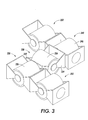
- Fig. 3 illustrates another possible configuration, in which five modules 310, 320, 330, 340 and 350 are connected such that central module 330 connects two pairs of modules.
- the first pair of modules, 310 and 320 extends from one support structure 332 of module 330, while the second pair of modules, 340 and 350, extend from a second support structure 334 of module 330.
- modules 320 and 340 may move rotationally about an axis extending through the center of actuator 336 of module 330.
- Module 310 may move rotationally about an axis extending through the center of actuator 326 of module 320;
- module 350 may move rotationally about an axis extending through the center of actuator 346 of module 340.
- Fig. 4 is similar to Fig. 3 except that the central module is rotated 90 degrees. This illustrates the use of a connection plate having symmetries that allow different ways to attach modules.
- passive components 412, 422, 442 and 452 are attached to the ends of modules 410, 420, 440 and 450 respectively.
- the passive components allow the modules to which they are attached to function as feet and modules 410, 420, 440 and 450 to function as legs.
- Rotation of module 430 allows the translation of the legs; rotation of the leg modules allows the feet to be lifted from the ground.
- Other types of passive components permitting other functionalities could also be attached to the modules.
- Figs. 2-4 illustrate only three of many configurations which it is possible to construct using the modules described herein in any number and connection pattern.
- One skilled in the art will readily appreciate that with a sufficient number of modules and various types of passive components, the potential number of configurations is almost limitless.
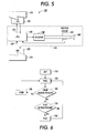
- the basic system 500 includes a plurality of modules 510, all of which contain a CPU 520, which may include embedded or external memory. For the purposes of clarity, the details of the configuration of this embodiment are shown on the central module only.
- Each module also includes actuator 540 and joint position sensor 550.
- CPUs 520 communicate with each other through network communication links 570, which connect to each module. Communication among the modules may be through infrared light, radio frequency transmission, or other means of communication, such as electrical signals transmitted by making electrical contact, by induced electrical signals, or by audio or vibrational signals.
- the position sensor senses the position of the output shaft 560 which is connected to the structure of the module. This sensor senses the motion of the output shaft whether it is driven by the actuator or whether it is back driven by motion of the structure from the environment, for example, a user moving the structure.
- a module is initiated with an input to the system, which may take numerous forms.
- a power-on signal may be sent to the system from an on/off control source, or a signal may be provided by movement of a hand in front of a proximity detector.
- a Hall effect sensor could provide an initiating signal when activated by a magnet
- a light detector could provide an initiating signal when activated by a beam of light
- an audio sensor could provide an initiating signal when activated by a sound, such as the clapping of hands.
- the operator moves, or poses, a module joint to a desired position. In the case in which many modules are connected together, the user may pose the modules by moving many modules simultaneously. This provides an intuitive, easy method to program many modules, which would be time consuming and tedious one module at a time.
- the input to the system to indicate a pose to be stored may be a button or force sensor on each module, or a wireless means of indicating to the modules that a state should be stored.
- wireless means include an infrared light or a radio signal that is sensed by each active module.
- Other possible means of indicating to the modules that a state should be stored include a magnetic signal sensed by a Hall effect sensor, or an audio signal sensed by an audio sensor.
- the system could automatically store states without the need for user input by recording states at specified time intervals. For example, every second, many times per second, or at pre-specified or on-line calculated time steps.
- Another possible method for storing states without the need for user input is sensing of joint motion for a specified period of time or when a change in the direction of the velocity is detected. When all joints stop moving, the state is stored as a pose.
- a signal is passed through the communications means 570 to all the CPUs of the robotic joint modules in the system.
- Each robotic joint module reads its respective joint position sensor and stores the position in the individual module's memory as a step in the motion program. This occurs simultaneously for all the modules, which is advantageous for a system of many modules.
- the joint position data for all the robotic joint modules may be stored in one computer in one module or a subset of the modules instead of being distributed among all of the robotic joint modules. If a single robotic joint module contains sufficient memory capability, the motion program may be stored on that module. Alternatively, the program may be stored on a removable medium. The program sequence then returns to step 720 and the sequence of steps 720, 760 and 730 is repeated
- the play button is pressed at step 770.
- the input to the system to indicate poses to be played may include any of the means described above for performance of step 760. Whenever this input is indicated, the system plays back the stored motion program.
- the motion sequence may be modified or altered by the system. For example, the speed of execution of the motion sequence may be enhanced or reduced, or the positions may be altered through smoothing or exaggeration.
- the motion sequence program may have positions appended to it even after the motions are played back. This facilitates the construction of the motion sequence program, since the user may play back shorter portions of the program before adding on the final positions.
- FIG. 7 there is shown a block diagram of an alternate embodiment of the system disclosed herein.
- This embodiment includes multiple modules 610, each having CPUs 620. For the purposes of clarity, the details of the configuration of this embodiment are shown on the central module only, however, this configuration embodiment may be present in some or all of the interconnected modules of the system.
- the module of this embodiment includes actuator 640 and joint position sensor 650, corresponding to actuator 540 and joint position sensor 550 described hereinabove.
- This embodiment also features an additional transmission 630.
- This non-backdriveable transmission also has a torque limiting clutch to allow motion of the modules with sufficient force but no motion otherwise. This advantageously allows the system to be posed without having to continuously support the modules, which would otherwise move, possibly due to gravity or other environmental forces.
- the modules communicate over communication links 615.
- an optional personal computer or remote controller 670 with input devices external to the robotic device, may be used to edit the motion program or serve as a mass storage or back-up storage device.
- Personal computer or remote controller 670 communicates with the system over communication links 675.
- the remote controller may be used to explicitly change the behavior of the modules and the system as the motion sequence program is being played back and reviewed. These changes may then either be stored and incorporated into the motion sequence program or ignored.
- Sensors 650 may be used as inputs to the program for initiation or indication of a step to be recorded as described above.
- a module is initiated with an input to the system, which may take numerous forms.
- a power-on signal may be sent to the system from an on/off control source, or a signal may be provided by movement of a hand in front of a proximity detector.
- a Hall effect sensor could provide an initiating signal when activated by a magnet
- a light detector could provide an initiating signal when activated by a beam of light
- an audio sensor could provide an initiating signal when activated by a sound, such as the clapping of hands.
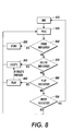
- step 820 the operator moves, or poses, a module joint to a desired position.
- steps 850, 860, 870 and 880 a check is made to determine if a signal is indicated.
- the input to the system for any of these indications may be a button pressed or force sensed on each module, or a wireless means of indicating to the modules. Examples of possible wireless means include an infrared light or a radio signal that is sensed by each active module.
- a decision is made by the user as to whether to store the current joint positions.
- the system could automatically store states without the need for user input by recording states at specified time intervals. For example, every second or at pre-specified or on-line calculated time steps. Another possible method for storing states without need for user input is sensing of joint motion.
- Storage of a position is comprised of reading a joint sensor and storing that data, for example by writing to a memory location in available random access memory (RAM), read only memory, or other non-volatile RAM.
- RAM random access memory
- read only memory or other non-volatile RAM.
- the system is reinitialized, the current motion program is lost, and the programming sequence begins again.
- the play indicated step 880 causes step 840 to be executed, which results in the play back of the current motion program.
- the indication steps 850, 860, 870 and 880 may still be monitored. For example if a delete is indicated, the position that the motion program is currently executing could be deleted from the motion program by jumping to step 890.
- there are many types of indicator or system instruction steps that may be used in addition to or in place of the steps for storing, deleting, playing and resetting described hereinabove.
- One such example is storage for joint positions of subsets of modules which facilitates the building up of complex motions with large numbers of modules.
- a large system may be composed by building motion programs with portions of modules, then combining the groups together. One play indicator would then cause all of the subgroups to act together. If the motion programs of the subgroups were of differing lengths, several actions could occur. The shorter programs may stop motion until the longer programs reach completion; the shorter programs may repeat until the longer programs reach completion; or each step of the shorter programs could be slowed down such that all programs end simultaneously.
- a group of modules may be posed and programmed to form a walking platform.
- a second group may be posed and programmed to form a swinging arm function. Attaching the two together and executing them simultaneously creates a robot that may battle another programmed robot in a robot battle competition game.
- Alternative indicators could include a stop or pause indicator, a fast forward, rewind, or reverse instruction steps.
- Editing may be performed on the robotic system itself, on a remote unit (e.g. a hand held computer or a mobile telephone, on a personal computer, or any other source capable of reviewing a control program). Editing may take several forms, for example, stepping through a sequence of movements, stopping at a movement to be changed, and inserting, deleting, or moving the previously stored position. Alternatively a sequence of movements may be edited by uploading the program for the sequence of movements to an external computer, graphically editing the sequence, and then downloading the edited sequence to the system.
- the stored sequence of events is played.
- the system of robotic modules may repeat the sequence of movements multiple times, for example, if a few steps of a walking gait are input as positions, then the system may walk continuously. Alternatively, the system may run the sequence once and then stop, or it may run it for a specified number of times. Each of these behaviors may be indicated through interactions with the sensors.
- the control of the system between poses may be a gait control table.
- a sequence of behaviors controls the behavior of each module.
- such behavior could be an open loop timed motion of a module, perhaps movement of a leg from a zero degree position to a ten degree position at a specified speed.
- a form of closed loop feedback from a position or joint angle sensor on each module could servo movement from one position to another on the table.
- Each module may begin at the top of the table and move from one behavior to the next in the table until the end of the table is reached, when the cycle starts over.
- a table may be structured specifying angles for each of the joints of the module at a specified elapsed time.
- the modules interpolate the joint angles during the time between each specified time in the table.
- the gait is repeating, so only the non-repeating portion of the table needs to be stored as the program for the gait.
- the program is distributed among the modules such that each module only stores the portion of the table that corresponds to its own movements. This requires less program memory space for each module, which enables the system to store longer and more complex programs.
- the system becomes scalable with regards to program space. As more modules are added, the program space increases at the same rate that the table increases. If the control program were stored in only one computer, or the entire program for all modules were stored in every module, as modules are added the size of the table or the control program would grow linearly, but the program space would remain unchanged.
- the controllers must be coordinated. This may be achieved by the system indicating a signal to synchronize the controllers.
- the signal may be a one-time event such as power being provided to the system, or a button on one module may be pressed, thereby sending a signal to all the other modules.
- the controller of one of the modules may send a signal under its own program, its own interpretation of its own sensors, or a combination of information obtained from communicating with other modules about the system's state.
- the signal may also be a continuing regular signal such as the tick of a clock to maintain continual closed loop synchronization, or it may be non-regular depending on other system events.
- the same motion program that is programmed in to one set of modules may be used to control a plurality of modules.
- a set of motions for a dance may be programmed into one set of modules.
- This same motion program could be used such that a dance troupe of many groups of robotic modules will dance together.
- a single wireless indicator may be used so that they run in a synchronized fashion.
- a repeating gait may be used to form a parade of walking robots.
- Code as used herein, or “program” as used herein, is any plurality of binary values or any executable, interpreted or compiled code which can be used by a computer or execution device to perform a task. This code or program can be written in any one of several known computer languages.
- a "computer”, as used herein, can mean any device which stores, processes, routes, manipulates, or performs like operation on data.
Landscapes
- Engineering & Computer Science (AREA)
- Robotics (AREA)
- Mechanical Engineering (AREA)
- Health & Medical Sciences (AREA)
- General Health & Medical Sciences (AREA)
- Orthopedic Medicine & Surgery (AREA)
- Toys (AREA)
- Manipulator (AREA)
Applications Claiming Priority (2)
| Application Number | Priority Date | Filing Date | Title |
|---|---|---|---|
| US938924 | 2001-08-24 | ||
| US09/938,924 US6454624B1 (en) | 2001-08-24 | 2001-08-24 | Robotic toy with posable joints |
Publications (2)
| Publication Number | Publication Date |
|---|---|
| EP1287868A2 true EP1287868A2 (de) | 2003-03-05 |
| EP1287868A3 EP1287868A3 (de) | 2004-01-02 |
Family
ID=25472214
Family Applications (1)
| Application Number | Title | Priority Date | Filing Date |
|---|---|---|---|
| EP02018930A Withdrawn EP1287868A3 (de) | 2001-08-24 | 2002-08-23 | Spielzeugroboter mit positionierbaren Gelenken |
Country Status (3)
| Country | Link |
|---|---|
| US (1) | US6454624B1 (de) |
| EP (1) | EP1287868A3 (de) |
| JP (1) | JP2003191185A (de) |
Cited By (5)
| Publication number | Priority date | Publication date | Assignee | Title |
|---|---|---|---|---|
| CN102765087A (zh) * | 2012-07-31 | 2012-11-07 | 东南大学 | 一种模块化自重构机器人及其变形控制方法 |
| CN104400794A (zh) * | 2014-10-29 | 2015-03-11 | 常州先进制造技术研究所 | 一种中空结构的双臂机器人模块化关节 |
| WO2015159077A3 (en) * | 2014-04-15 | 2015-12-10 | Asque Limited | Article moveable between two positions and a method of combining two or more of the same |
| EP3476548A1 (de) * | 2017-10-27 | 2019-05-01 | Creaholic SA | Hardwaremodul für ein robotisches system und mechanische kopplung |
| EP3476549A1 (de) * | 2017-10-27 | 2019-05-01 | Creaholic SA | Hardware-modul, robotersystem und verfahren zum betrieb des robotersystems |
Families Citing this family (75)
| Publication number | Priority date | Publication date | Assignee | Title |
|---|---|---|---|---|
| DK174581B1 (da) * | 1999-11-17 | 2003-06-30 | Lego As | Et legetøjsbyggesæt |
| JP2001321579A (ja) * | 2000-05-15 | 2001-11-20 | Saamaru:Kk | コントローラ |
| US6575802B2 (en) * | 2001-08-24 | 2003-06-10 | Xerox Corporation | Robotic toy modular system with distributed program |
| US6605914B2 (en) * | 2001-08-24 | 2003-08-12 | Xerox Corporation | Robotic toy modular system |
| US6877574B2 (en) * | 2001-09-14 | 2005-04-12 | Massachusetts Institute Of Technology | Modular robotic teaching tool |
| JP3756095B2 (ja) * | 2001-10-01 | 2006-03-15 | 日本サーボ株式会社 | 多関節型の産業用ロボット及び当該ロボットのアームユニット |
| KR100578342B1 (ko) * | 2003-01-03 | 2006-05-11 | 주식회사 메가로보틱스 | 인공지능형 로봇완구 및 그 제어방법 |
| US7238079B2 (en) * | 2003-01-14 | 2007-07-03 | Disney Enterprise, Inc. | Animatronic supported walking system |
| JP4638740B2 (ja) * | 2003-01-15 | 2011-02-23 | ピエトルズク,アンジェイ | 三次元多目的素子システムおよび三次元多目的素子を生成するための方法 |
| US7154362B2 (en) * | 2003-11-12 | 2006-12-26 | Honeywell International, Inc. | Robotic member |
| EP1727652A1 (de) * | 2003-12-01 | 2006-12-06 | Newsouth Innovations Pty Limited | Verfahren zur steuerung eines aus untereinander abhängigen einheiten gebildeten systems |
| US7747352B2 (en) * | 2004-04-20 | 2010-06-29 | Massachusetts Institute Of Technology | Physical modeling system for constructing and controlling articulated forms with motorized joints |
| US6918811B1 (en) * | 2004-10-01 | 2005-07-19 | Sheng-Chien Wang | Robotic toy |
| US20070059124A1 (en) * | 2005-08-25 | 2007-03-15 | Palo Alto Research Center Incorporated | Portable personal wearable active third arm |
| NL1030221C2 (nl) * | 2005-10-18 | 2007-04-19 | Eaton Automotive Bv | Aandrijfsysteem, aandrijfmodule en binnenspiegeleenheid voor een motorvoertuig. |
| USD569923S1 (en) | 2006-05-04 | 2008-05-27 | Mattel, Inc. | Snake toy vehicle |
| ATE543548T1 (de) * | 2006-05-04 | 2012-02-15 | Mattel Inc | Motorisierte spielzeugfigur |
| JP4551893B2 (ja) * | 2006-12-27 | 2010-09-29 | 株式会社タカラトミー | ロボット玩具 |
| KR100903667B1 (ko) * | 2007-08-02 | 2009-06-18 | (주)로보티즈 | 네트워크에 기반한 로봇 콘텐츠 거래 시스템 및 방법 |
| KR100882920B1 (ko) | 2007-11-30 | 2009-02-10 | 한국기계연구원 | 모듈형 로봇 구동부의 구조 |
| JP4397412B2 (ja) * | 2007-12-07 | 2010-01-13 | 株式会社タカラトミー | ロボット玩具およびその組立方法 |
| WO2009100051A1 (en) * | 2008-02-04 | 2009-08-13 | Polchin George C | Physical data building blocks system for video game interaction |
| JP5541600B2 (ja) * | 2009-02-05 | 2014-07-09 | コリア・インスティテュート・オブ・マシナリー・アンド・マテリアルズ | モジュール型ロボット駆動部の構造 |
| KR101095015B1 (ko) | 2009-06-17 | 2011-12-20 | 세명대학교 산학협력단 | 모듈러 로봇 및 그의 제어방법 |
| US8742814B2 (en) | 2009-07-15 | 2014-06-03 | Yehuda Binder | Sequentially operated modules |
| WO2011011084A1 (en) | 2009-07-24 | 2011-01-27 | Modular Robotics Llc | Modular robotics |
| US8602833B2 (en) | 2009-08-06 | 2013-12-10 | May Patents Ltd. | Puzzle with conductive path |
| US8425620B2 (en) | 2009-12-08 | 2013-04-23 | Hdt Engineering Services, Inc. | Modular limb segment connector |
| DE102010062217B4 (de) * | 2010-01-22 | 2018-11-22 | Kinematics Gmbh | Baukastensystem mit bewegungsfähigen Modulen |
| US8336420B2 (en) | 2010-06-02 | 2012-12-25 | Disney Enterprises, Inc. | Three-axis robotic joint using four-bar linkages to drive differential side gears |
| KR101198076B1 (ko) * | 2010-06-16 | 2012-11-09 | 서강대학교산학협력단 | 공벌레 형태를 모방한 이동장치 |
| US9321172B2 (en) | 2011-05-13 | 2016-04-26 | Hdt Expeditionary Systems, Inc. | Modular rotational electric actuator |
| US9597607B2 (en) | 2011-08-26 | 2017-03-21 | Littlebits Electronics Inc. | Modular electronic building systems with magnetic interconnections and methods of using the same |
| US11330714B2 (en) | 2011-08-26 | 2022-05-10 | Sphero, Inc. | Modular electronic building systems with magnetic interconnections and methods of using the same |
| US9019718B2 (en) | 2011-08-26 | 2015-04-28 | Littlebits Electronics Inc. | Modular electronic building systems with magnetic interconnections and methods of using the same |
| EP2773436A4 (de) | 2011-10-31 | 2016-05-04 | Modular Robotics Inc | Kinematische modularer bausatz |
| KR101255848B1 (ko) * | 2011-11-24 | 2013-04-17 | 박남영 | 로봇 조립블럭용 모터블럭 조립체 |
| US9931581B2 (en) * | 2012-04-26 | 2018-04-03 | Victor A. Grossman | Helical spring toy and method of use thereof |
| FR2991221B1 (fr) * | 2012-06-01 | 2015-02-27 | Aldebaran Robotics | Colonne vertebrale pour robot humanoide |
| DE102012017305A1 (de) * | 2012-09-03 | 2014-03-06 | Leonhard Oschütz | Verbindungskonstruktion zwischen Konstruktionselementen und Konstruktionselement |
| US10372115B2 (en) * | 2012-10-26 | 2019-08-06 | Board Of Regents, The University Of Texas System | Modular and reconfigurable manufacturing systems |
| CN103264389B (zh) * | 2013-05-14 | 2015-09-16 | 东南大学 | 一种可全向运动的模块化自重构机器人的单元模块结构 |
| US9555326B2 (en) | 2014-03-11 | 2017-01-31 | Microsoft Technology Licensing, Llc | Gaming system for modular toys |
| US9703896B2 (en) | 2014-03-11 | 2017-07-11 | Microsoft Technology Licensing, Llc | Generation of custom modular objects |
| US9592443B2 (en) | 2014-03-11 | 2017-03-14 | Microsoft Technology Licensing, Llc | Data store for a modular assembly system |
| US9526979B2 (en) | 2014-03-11 | 2016-12-27 | Microsoft Technology Licensing, Llc | Storing state for physical modular toys |
| US10150043B2 (en) | 2014-03-11 | 2018-12-11 | Microsoft Technology Licensing, Llc | Interactive smart beads |
| US10188939B2 (en) | 2014-03-11 | 2019-01-29 | Microsoft Technology Licensing, Llc | Modular construction for interacting with software |
| US9597796B2 (en) * | 2014-05-09 | 2017-03-21 | Carnegie Mellon University, CTTEC | Systems and methods for modular units in electro-mechanical systems |
| US10478723B2 (en) | 2014-06-30 | 2019-11-19 | Microsoft Technology Licensing, Llc | Track based play systems |
| US10537821B2 (en) | 2014-06-30 | 2020-01-21 | Microsoft Technology Licensing, Llc | Interactive play sets |
| US10518188B2 (en) | 2014-06-30 | 2019-12-31 | Microsoft Technology Licensing, Llc | Controlling physical toys using a physics engine |
| US9345982B2 (en) | 2014-09-01 | 2016-05-24 | Joseph Farco | Building block universal joint system |
| US10369477B2 (en) | 2014-10-08 | 2019-08-06 | Microsoft Technology Licensing, Llc | Management of resources within a virtual world |
| US9919226B2 (en) | 2014-10-08 | 2018-03-20 | Microsoft Technology Licensing, Llc | Storage and charging device for game pieces |
| US9696757B2 (en) | 2014-10-08 | 2017-07-04 | Microsoft Corporation | Transfer of attributes between generations of characters |
| US9592603B2 (en) * | 2014-12-01 | 2017-03-14 | Spin Master Ltd. | Reconfigurable robotic system |
| US11400595B2 (en) | 2015-01-06 | 2022-08-02 | Nexus Robotics Llc | Robotic platform with area cleaning mode |
| US10518407B2 (en) | 2015-01-06 | 2019-12-31 | Discovery Robotics | Apparatus and methods for providing a reconfigurable robotic platform |
| US10328573B2 (en) * | 2015-01-06 | 2019-06-25 | Discovery Robotics | Robotic platform with teach-repeat mode |
| US20190232184A1 (en) * | 2015-06-25 | 2019-08-01 | Patently Good Pty Ltd | Modular Electronics System |
| US10955977B2 (en) | 2015-11-03 | 2021-03-23 | Microsoft Technology Licensing, Llc | Extender object for multi-modal sensing |
| US10649572B2 (en) | 2015-11-03 | 2020-05-12 | Microsoft Technology Licensing, Llc | Multi-modal sensing surface |
| US10338753B2 (en) | 2015-11-03 | 2019-07-02 | Microsoft Technology Licensing, Llc | Flexible multi-layer sensing surface |
| US10293482B2 (en) * | 2015-11-12 | 2019-05-21 | ITI Electromagnetic Products Inc. | Self-assembling robotic construction system and associated methods |
| US9914066B2 (en) * | 2016-03-07 | 2018-03-13 | Microsoft Technology Licensing, Llc | Electromagnetically coupled building blocks |
| CN205752715U (zh) * | 2016-03-31 | 2016-11-30 | 深圳贝尔创意科教有限公司 | 连接结构及应用该连接结构的电子装置 |
| KR101842422B1 (ko) * | 2016-07-26 | 2018-03-28 | 한국원자력연구원 | 고방사선 내 작업용 매니퓰레이터 |
| US10471605B2 (en) * | 2017-04-26 | 2019-11-12 | Ready Robotics | Programmable adapters for detachably connecting robotic peripherals to adaptively retool robots |
| CN108312146B (zh) * | 2018-01-31 | 2020-11-20 | 南京工程学院 | 模块化机器人分散控制方法及系统 |
| US10668398B2 (en) * | 2018-10-30 | 2020-06-02 | Joel Allen Schulz | Curiosity revealing or animating a shaped cavity |
| US11616844B2 (en) | 2019-03-14 | 2023-03-28 | Sphero, Inc. | Modular electronic and digital building systems and methods of using the same |
| CN112208804B (zh) * | 2020-09-22 | 2021-07-20 | 哈尔滨工业大学 | 空间可重构桁架式抓捕机构及其抓捕方法 |
| CN117018639A (zh) * | 2023-08-18 | 2023-11-10 | 蔡泽銮 | 一种拼装机器人玩具 |
| US12594509B2 (en) | 2023-08-19 | 2026-04-07 | Farco ToyCo LLC | Interconnecting methods and systems for posable bendable building block toys |
Family Cites Families (28)
| Publication number | Priority date | Publication date | Assignee | Title |
|---|---|---|---|---|
| US4391060A (en) * | 1981-08-21 | 1983-07-05 | Takara Co., Ltd. | Toy robot vehicle assembly |
| JPS598990A (ja) * | 1982-07-07 | 1984-01-18 | 株式会社バンダイ | 形態変化ロボット玩具の脚部装置 |
| JPS6080591A (ja) * | 1983-10-05 | 1985-05-08 | 株式会社日立製作所 | マニプレ−タ |
| JPS60128699U (ja) * | 1984-02-07 | 1985-08-29 | 株式会社トミー | 無線操縦玩具 |
| US4712184A (en) * | 1984-09-12 | 1987-12-08 | Haugerud Albert R | Computer controllable robotic educational toy |
| US4813907A (en) * | 1986-05-05 | 1989-03-21 | Tiger Electronic Sales, Ltd. | Toy vehicle with graphics display |
| US5053976A (en) * | 1989-05-22 | 1991-10-01 | Honda Giken Kogyo Kabushiki Kaisha | Method of teaching a robot |
| JPH0639754Y2 (ja) * | 1989-08-08 | 1994-10-19 | 株式会社トミー | 走行玩具のサイレン音吹鳴機構 |
| JPH05111885A (ja) * | 1991-08-30 | 1993-05-07 | Toshiba Corp | マニピユレータ装置 |
| JP3609435B2 (ja) * | 1991-11-25 | 2005-01-12 | 株式会社東芝 | マニピュレータ装置 |
| JPH05154778A (ja) * | 1991-12-02 | 1993-06-22 | Toshiba Corp | マニピュレ−タ |
| JPH0623152A (ja) * | 1992-07-06 | 1994-02-01 | Takara Co Ltd | 連結玩具 |
| US5346418A (en) * | 1992-10-01 | 1994-09-13 | Toy Biz, Inc. | Kit for assembling toy weapons |
| US5456568A (en) * | 1993-12-27 | 1995-10-10 | Kirby; Jeffrey R. | Arm mechanism |
| JPH07251389A (ja) * | 1994-03-16 | 1995-10-03 | Toshiba Corp | マニピュレータ装置 |
| DE19517852A1 (de) * | 1995-05-16 | 1995-12-14 | Uwe Kochanneck | Multiblock Robot |
| JP2699941B2 (ja) * | 1995-07-20 | 1998-01-19 | 日本電気株式会社 | ロボット関節 |
| US5699695A (en) * | 1996-05-01 | 1997-12-23 | Virginia Tech Intellectual Properties, Inc. | Spatial, parallel-architecture robotic carpal wrist |
| JP3193878B2 (ja) * | 1996-10-17 | 2001-07-30 | ファナック株式会社 | 嵌合作業を行なうための協調ロボットシステム |
| IL120857A (en) | 1997-05-19 | 2003-03-12 | Creator Ltd | Programmable assembly toy |
| GB9713765D0 (en) * | 1997-07-01 | 1997-09-03 | Engineering Services Inc | Reconfigurable mudular drive system |
| JP3919040B2 (ja) | 1997-11-30 | 2007-05-23 | ソニー株式会社 | ロボツト装置 |
| US6071166A (en) * | 1998-04-21 | 2000-06-06 | Toymax Inc. | Light shooting and detecting toy figures |
| US6346025B1 (en) * | 1998-06-19 | 2002-02-12 | Titanium Toys, Inc. | Methods and systems for joints useable in toys |
| US6233502B1 (en) * | 1998-10-16 | 2001-05-15 | Xerox Corporation | Fault tolerant connection system for transiently connectable modular elements |
| KR100625134B1 (ko) | 1999-02-04 | 2006-09-26 | 레고 에이/에스 | 마이크로 프로세서 제어 완구 조립 요소 및 완구 조립 세트 |
| KR20010103757A (ko) | 1999-02-04 | 2001-11-23 | 브라이언 쏘렌센 / 스텐 쥬울 피터슨 | 시각적 프로그래밍을 구비한 마이크로 프로세서 제어 완구조립 요소 |
| US6377013B2 (en) * | 1999-12-24 | 2002-04-23 | Honda Giken Kogyo Kabushiki Kaisha | Control apparatus for legged mobile robot |
-
2001
- 2001-08-24 US US09/938,924 patent/US6454624B1/en not_active Expired - Lifetime
-
2002
- 2002-08-16 JP JP2002237406A patent/JP2003191185A/ja active Pending
- 2002-08-23 EP EP02018930A patent/EP1287868A3/de not_active Withdrawn
Cited By (13)
| Publication number | Priority date | Publication date | Assignee | Title |
|---|---|---|---|---|
| CN102765087A (zh) * | 2012-07-31 | 2012-11-07 | 东南大学 | 一种模块化自重构机器人及其变形控制方法 |
| CN102765087B (zh) * | 2012-07-31 | 2014-08-20 | 东南大学 | 一种模块化自重构机器人及其变形控制方法 |
| WO2015159077A3 (en) * | 2014-04-15 | 2015-12-10 | Asque Limited | Article moveable between two positions and a method of combining two or more of the same |
| US10252175B2 (en) | 2014-04-15 | 2019-04-09 | Boti Global Limited | Article moveable between two positions and a method of combining two or more of the same |
| CN104400794A (zh) * | 2014-10-29 | 2015-03-11 | 常州先进制造技术研究所 | 一种中空结构的双臂机器人模块化关节 |
| CN104400794B (zh) * | 2014-10-29 | 2016-08-24 | 常州先进制造技术研究所 | 一种中空结构的双臂机器人模块化关节 |
| EP3476548A1 (de) * | 2017-10-27 | 2019-05-01 | Creaholic SA | Hardwaremodul für ein robotisches system und mechanische kopplung |
| EP3476549A1 (de) * | 2017-10-27 | 2019-05-01 | Creaholic SA | Hardware-modul, robotersystem und verfahren zum betrieb des robotersystems |
| WO2019081660A1 (en) | 2017-10-27 | 2019-05-02 | Creaholic S.A. | HARDWARE MODULE, ROBOTIC SYSTEM AND METHOD OF OPERATING THE ROBOTIC SYSTEM |
| WO2019081662A1 (en) | 2017-10-27 | 2019-05-02 | Creaholic S.A. | MATERIAL MODULE FOR ROBOTIC SYSTEM, AND MECHANICAL COUPLING DEVICE |
| KR20200073233A (ko) * | 2017-10-27 | 2020-06-23 | 페스토 에스이 운트 코. 카게 | 하드웨어 모듈, 로봇 시스템 및 로봇 시스템을 작동시키기 위한 방법 |
| KR20200073232A (ko) * | 2017-10-27 | 2020-06-23 | 페스토 에스이 운트 코. 카게 | 로봇 시스템에 대한 하드웨어 모듈 및 기계적 커플링 |
| US11597076B2 (en) | 2017-10-27 | 2023-03-07 | Festo Se & Co. Kg | Hardware module for a robotic system, and mechanical coupling |
Also Published As
| Publication number | Publication date |
|---|---|
| EP1287868A3 (de) | 2004-01-02 |
| US6454624B1 (en) | 2002-09-24 |
| JP2003191185A (ja) | 2003-07-08 |
Similar Documents
| Publication | Publication Date | Title |
|---|---|---|
| US6454624B1 (en) | Robotic toy with posable joints | |
| US6575802B2 (en) | Robotic toy modular system with distributed program | |
| US7113833B1 (en) | Selection and control of motion data | |
| JP4557488B2 (ja) | ロボット玩具モジュラーシステム | |
| KR100495963B1 (ko) | 로봇장치및그제어방법 | |
| US9592603B2 (en) | Reconfigurable robotic system | |
| EP2196248B1 (de) | Spielzeugroboter und Montageverfahren dafür | |
| US5697829A (en) | Programmable toy | |
| US9308643B2 (en) | Transferable intelligent control device | |
| US6736694B2 (en) | Amusement device | |
| Fujita | Digital creatures for future entertainment robotics | |
| WO2001085400A2 (en) | Self-stabilizing walking apparatus that is capable of being reprogrammed or puppeteered | |
| JP2003080477A (ja) | ロボット装置及びロボット装置の跳躍制御方法 | |
| WO2000045925A1 (en) | A programmable toy with communication means | |
| KR19990045689A (ko) | 로봇 장치 및 그 구동 제어 방법 | |
| EP2773436A1 (de) | Kinematische modularer bausatz | |
| JP2002536088A (ja) | ビジュアルプログラミングを伴うマイクロプロセッサ制御式の玩具の組立要素 | |
| Pacheco et al. | Fable: Design of a modular robotic playware platform | |
| Pierris et al. | An interactive tool for designing complex robot motion patterns | |
| JP3446933B2 (ja) | ロボツト装置及びその制御方法 | |
| JP7055416B2 (ja) | 多関節ロボットにおける動作教示・再現駆動システム及び動作教示・再現駆動方法 | |
| JP2004073306A (ja) | 操縦可能な歩行玩具 | |
| Pierris | Soccer skills for humanoid robots | |
| Rubia Estruch | Model and build robot in ROS environment | |
| Puligari | Design and development of a one-degree-of-freedom force-reflecting manual controller prototype for teleoperation |
Legal Events
| Date | Code | Title | Description |
|---|---|---|---|
| PUAI | Public reference made under article 153(3) epc to a published international application that has entered the european phase |
Free format text: ORIGINAL CODE: 0009012 |
|
| AK | Designated contracting states |
Kind code of ref document: A2 Designated state(s): AT BE BG CH CY CZ DE DK EE ES FI FR GB GR IE IT LI LU MC NL PT SE SK TR Designated state(s): AT BE BG CH CY CZ DE DK EE ES FI FR GB GR IE IT LI LU MC NL PT SE SK TR |
|
| AX | Request for extension of the european patent |
Extension state: AL LT LV MK RO SI |
|
| RIC1 | Information provided on ipc code assigned before grant |
Ipc: 7B 25J 17/02 B Ipc: 7B 25J 9/08 B Ipc: 7B 25J 9/16 B Ipc: 7A 63H 33/04 B Ipc: 7A 63H 3/04 A |
|
| PUAL | Search report despatched |
Free format text: ORIGINAL CODE: 0009013 |
|
| AK | Designated contracting states |
Kind code of ref document: A3 Designated state(s): AT BE BG CH CY CZ DE DK EE ES FI FR GB GR IE IT LI LU MC NL PT SE SK TR |
|
| AX | Request for extension of the european patent |
Extension state: AL LT LV MK RO SI |
|
| 17P | Request for examination filed |
Effective date: 20040702 |
|
| AKX | Designation fees paid |
Designated state(s): DE FR GB |
|
| 17Q | First examination report despatched |
Effective date: 20071002 |
|
| STAA | Information on the status of an ep patent application or granted ep patent |
Free format text: STATUS: THE APPLICATION IS DEEMED TO BE WITHDRAWN |
|
| 18D | Application deemed to be withdrawn |
Effective date: 20090724 |