EP1287875A2 - Dispositif pour séparer et récupérer des composés perfluoriques gazeux - Google Patents
Dispositif pour séparer et récupérer des composés perfluoriques gazeux Download PDFInfo
- Publication number
- EP1287875A2 EP1287875A2 EP02292630A EP02292630A EP1287875A2 EP 1287875 A2 EP1287875 A2 EP 1287875A2 EP 02292630 A EP02292630 A EP 02292630A EP 02292630 A EP02292630 A EP 02292630A EP 1287875 A2 EP1287875 A2 EP 1287875A2
- Authority
- EP
- European Patent Office
- Prior art keywords
- membrane
- permeate
- gas
- conduit
- stream
- Prior art date
- Legal status (The legal status is an assumption and is not a legal conclusion. Google has not performed a legal analysis and makes no representation as to the accuracy of the status listed.)
- Withdrawn
Links
- 0 CC*1CC2C(C)C*(CC)(CC)CC2C1 Chemical compound CC*1CC2C(C)C*(CC)(CC)CC2C1 0.000 description 1
Images





Classifications
-
- B—PERFORMING OPERATIONS; TRANSPORTING
- B01—PHYSICAL OR CHEMICAL PROCESSES OR APPARATUS IN GENERAL
- B01D—SEPARATION
- B01D53/00—Separation of gases or vapours; Recovering vapours of volatile solvents from gases; Chemical or biological purification of waste gases, e.g. engine exhaust gases, smoke, fumes, flue gases, aerosols
- B01D53/22—Separation of gases or vapours; Recovering vapours of volatile solvents from gases; Chemical or biological purification of waste gases, e.g. engine exhaust gases, smoke, fumes, flue gases, aerosols by diffusion
- B01D53/225—Multiple stage diffusion
-
- B—PERFORMING OPERATIONS; TRANSPORTING
- B01—PHYSICAL OR CHEMICAL PROCESSES OR APPARATUS IN GENERAL
- B01D—SEPARATION
- B01D53/00—Separation of gases or vapours; Recovering vapours of volatile solvents from gases; Chemical or biological purification of waste gases, e.g. engine exhaust gases, smoke, fumes, flue gases, aerosols
- B01D53/22—Separation of gases or vapours; Recovering vapours of volatile solvents from gases; Chemical or biological purification of waste gases, e.g. engine exhaust gases, smoke, fumes, flue gases, aerosols by diffusion
-
- B—PERFORMING OPERATIONS; TRANSPORTING
- B01—PHYSICAL OR CHEMICAL PROCESSES OR APPARATUS IN GENERAL
- B01D—SEPARATION
- B01D53/00—Separation of gases or vapours; Recovering vapours of volatile solvents from gases; Chemical or biological purification of waste gases, e.g. engine exhaust gases, smoke, fumes, flue gases, aerosols
- B01D53/22—Separation of gases or vapours; Recovering vapours of volatile solvents from gases; Chemical or biological purification of waste gases, e.g. engine exhaust gases, smoke, fumes, flue gases, aerosols by diffusion
- B01D53/225—Multiple stage diffusion
- B01D53/226—Multiple stage diffusion in serial connexion
-
- B—PERFORMING OPERATIONS; TRANSPORTING
- B01—PHYSICAL OR CHEMICAL PROCESSES OR APPARATUS IN GENERAL
- B01D—SEPARATION
- B01D53/00—Separation of gases or vapours; Recovering vapours of volatile solvents from gases; Chemical or biological purification of waste gases, e.g. engine exhaust gases, smoke, fumes, flue gases, aerosols
- B01D53/22—Separation of gases or vapours; Recovering vapours of volatile solvents from gases; Chemical or biological purification of waste gases, e.g. engine exhaust gases, smoke, fumes, flue gases, aerosols by diffusion
- B01D53/229—Integrated processes (Diffusion and at least one other process, e.g. adsorption, absorption)
-
- C—CHEMISTRY; METALLURGY
- C07—ORGANIC CHEMISTRY
- C07C—ACYCLIC OR CARBOCYCLIC COMPOUNDS
- C07C17/00—Preparation of halogenated hydrocarbons
- C07C17/38—Separation; Purification; Stabilisation; Use of additives
-
- B—PERFORMING OPERATIONS; TRANSPORTING
- B01—PHYSICAL OR CHEMICAL PROCESSES OR APPARATUS IN GENERAL
- B01D—SEPARATION
- B01D2257/00—Components to be removed
- B01D2257/20—Halogens or halogen compounds
- B01D2257/204—Inorganic halogen compounds
-
- B—PERFORMING OPERATIONS; TRANSPORTING
- B01—PHYSICAL OR CHEMICAL PROCESSES OR APPARATUS IN GENERAL
- B01D—SEPARATION
- B01D2257/00—Components to be removed
- B01D2257/20—Halogens or halogen compounds
- B01D2257/206—Organic halogen compounds
- B01D2257/2066—Fluorine
-
- Y—GENERAL TAGGING OF NEW TECHNOLOGICAL DEVELOPMENTS; GENERAL TAGGING OF CROSS-SECTIONAL TECHNOLOGIES SPANNING OVER SEVERAL SECTIONS OF THE IPC; TECHNICAL SUBJECTS COVERED BY FORMER USPC CROSS-REFERENCE ART COLLECTIONS [XRACs] AND DIGESTS
- Y02—TECHNOLOGIES OR APPLICATIONS FOR MITIGATION OR ADAPTATION AGAINST CLIMATE CHANGE
- Y02C—CAPTURE, STORAGE, SEQUESTRATION OR DISPOSAL OF GREENHOUSE GASES [GHG]
- Y02C20/00—Capture or disposal of greenhouse gases
- Y02C20/30—Capture or disposal of greenhouse gases of perfluorocarbons [PFC], hydrofluorocarbons [HFC] or sulfur hexafluoride [SF6]
-
- Y—GENERAL TAGGING OF NEW TECHNOLOGICAL DEVELOPMENTS; GENERAL TAGGING OF CROSS-SECTIONAL TECHNOLOGIES SPANNING OVER SEVERAL SECTIONS OF THE IPC; TECHNICAL SUBJECTS COVERED BY FORMER USPC CROSS-REFERENCE ART COLLECTIONS [XRACs] AND DIGESTS
- Y02—TECHNOLOGIES OR APPLICATIONS FOR MITIGATION OR ADAPTATION AGAINST CLIMATE CHANGE
- Y02P—CLIMATE CHANGE MITIGATION TECHNOLOGIES IN THE PRODUCTION OR PROCESSING OF GOODS
- Y02P20/00—Technologies relating to chemical industry
- Y02P20/151—Reduction of greenhouse gas [GHG] emissions, e.g. CO2
-
- Y—GENERAL TAGGING OF NEW TECHNOLOGICAL DEVELOPMENTS; GENERAL TAGGING OF CROSS-SECTIONAL TECHNOLOGIES SPANNING OVER SEVERAL SECTIONS OF THE IPC; TECHNICAL SUBJECTS COVERED BY FORMER USPC CROSS-REFERENCE ART COLLECTIONS [XRACs] AND DIGESTS
- Y02—TECHNOLOGIES OR APPLICATIONS FOR MITIGATION OR ADAPTATION AGAINST CLIMATE CHANGE
- Y02P—CLIMATE CHANGE MITIGATION TECHNOLOGIES IN THE PRODUCTION OR PROCESSING OF GOODS
- Y02P20/00—Technologies relating to chemical industry
- Y02P20/151—Reduction of greenhouse gas [GHG] emissions, e.g. CO2
- Y02P20/155—Perfluorocarbons [PFC]; Hydrofluorocarbons [HFC]; Hydrochlorofluorocarbons [HCFC]; Chlorofluorocarbons [CFC]
Definitions
- the invention relates to the separation and recovery (or disposal) of perfluorocompound gases from a gas mixture. Especially, the invention relates to the concentrating of low concentration gas mixtures of perfluorocompound gases such as those present in the effluent of a semiconductor manufacturing process, particularly the etching and cleaning steps.
- perfluorocompounds such as CF 4 , C 2 F 6 , C 3 F 8 , C 4 F 10 , CHF 3 , SF 6 , NF 3 , and the like, in the semiconductor manufacturing processes involving gases, particularly in the various etching steps of the semiconductor manufacturing processes as well as in the chamber cleaning step of the manufacturing process.
- Those perfluorocompound gases are used either pure or diluted, for example with air or nitrogen or other inert gas or in admixture with other perfluorocompound gases or other carrier gases (for example inert gases).
- a selectively permeable membrane formed from an amorphous polymer of perfluoro 2-2 dimethyl 1-3-dioxole which is usable for separation of hydrocarbons or chlorofluorocarbons from, for example, air.
- Such a particular membrane apparently permeates oxygen and nitrogen faster than hydrocarbons and chlorofluorocarbons which can be recovered unexpectedly on the non-permeate side of the membrane, contrary to all of the membranes, including those disclosed in U.S. Patent 4,553,983 and 5,281,255.
- effluent gases for example, from a semiconductor manufacturing process, which comprise perfluorocompounds can be treated efficiently by using certain, preferably hollow fiber, membranes which permeate much faster the "carrier gases" of the effluent gas mixture, such as air, nitrogen, oxygen, argon and/or helium, than the PFCs of the gas mixture which are then recovered on the non-permeate side of the membrane.
- carrier gases such as air, nitrogen, oxygen, argon and/or helium
- Membranes are glassy polymeric membranes, more preferably asymmetric or composite (with an asymmetric outer layer) membranes. Preferably, these glassy polymeric membranes do not include perfluorinated membranes. However, the glassy polymeric membranes used in accordance with the invention can comprise a layer, including a posttreatment layer made of a fluorinated polymer such as polytetrafluoroethylene, amorphous perfluoro 2-2 dimethyl 1-3 dioxide, and the like.
- a fluorinated polymer such as polytetrafluoroethylene, amorphous perfluoro 2-2 dimethyl 1-3 dioxide, and the like.
- One aspect of the invention relates to a process to recover a perfluorocompound gas or gas mixture from a gas mixture flowing out from a semiconductor manufacturing process, comprising the steps of pretreating the gas mixture to substantially remove most of the harmful components (gas, particles, and the like) to the membrane and delivering a pretreated gas mixture, providing at least one glassy polymer membrane having a feed side and a permeate side, contacting the feed side of the membrane with the pretreated gas mixture at a first pressure, withdrawing the perfluorocompound gas or gas mixture from the feed side of the membrane at a pressure which is substantially equal to the first pressure and withdrawing a residue gas at a second pressure which is lower than the first pressure from the permeate side of the membrane.
- the semiconductor manufacturing process using PFCs may be selected from etching processes including oxide, metal and dielectric; deposition processes including silicon CVD, tungsten backetching, dry chamber cleaning, and the like.
- any kind of species which is present in the feed flow stream which may harm the membrane is removed by the scrubber means, including any harmful gaseous HF, NH 3 , WF 6 , O 3 , BCl 3 , and any corrosive species, also any pyrophoric species including silicon hydrides such as SiH 4 , and any particulates having vaerage diameter greater than about 20 micrometers, and any oil mists.
- any compressors used in the methods and systems of the invention be sealed and oil-free.
- One preferred aspect of the invention relates to a process to recover at least one perfluorocompound gas or gas mixture, comprising the steps of:
- the various PFCs are separated from each other, by well known methods per se, such as selective condensation or adsorption in order to recover either separate PFCs or mixtures of PFCs having close boiling points.
- the PFCs gas mixture is concentrated again, for example, with a second membrane, or the PFCs gas mixture is stored or recycled in the process (with or without additional treatment).
- PFC gas mixture may be compressed, at least partially liquefied, and stored for future use.
- Another feature of the invention includes the provision of a process step where the PFC gas mixture is concentrated using a plurality of membranes arranged in series, with the possibility of the concentrated PFC gas mixture from each membrane unit being capable of use as a sweep gas of the permeate side of any one of or all of the membrane units in the series.
- a further aspect of the invention is the provision of a PFC gas mixture surge tank prior to the PFCs being recycled into the semiconductor manufacturing process, or prior to being routed to storage.
- Another aspect of the invention is a semiconductor manufacturing system comprising :
- Preferred processes and systems of the invention include operating one or more of the membrane units at a constant concentration set-point for the PFC concentration in the non-permeate stream from each membrane unit.
- the set-point concentration of the PFC in the non-permeate stream from each succeeding PFC membrane separation unit would of course be higher than the immediately preceding one.
- Appropriate sensors can be inserted into the non-permeate effluent conduit from each membrane unit to continuously or non-continuously analyze for PFC concentration, or, samples may be taken periodically or continuously from the non-permeate effluent from each membrane unit, which may be sent to dedicated analyzers either on-site or off-site.
- This information is preferably then forwarded to a process controller which may control for example the pressure of the feed to each membrane unit, temperature, flow, and the like.
- a process controller which may control for example the pressure of the feed to each membrane unit, temperature, flow, and the like.
- the sweep gas may either be controlled via an open loop or a closed loop arrangement.
- Another preferred system and process embodiment of the present invention includes the recycle of the permeate stream of either the first or succeeding stages of the membrane units (in other words, the carrier gas and other process gases are recycled).
- the carrier gases may be recycled directly to the reactor chambers, or may be delivered to heat exchangers, compressors, and the like to reduce them to liquid form for storage or future use.
- a recycle membrane may be provided , functioning to separate air gases from process gases.
- Still other preferred processes and systems in accordance with the invention are those wherein one or more non-permeate streams is post-treated to remove non-perfluorocompounds.
- Post-treatment methods include those previously mentioned as suitable for pretreatment of the feed gas to the membrane.
- Another aspect of the invention is a method of recovery of a relatively pure PFC stream from a vent stream from one or more gas cabinets, tube trailers, clean rooms, or the like using a membrane unit as described herein.
- the non-permeate stream may either be rerouted to the semiconductor manufacturing reaction chamber, routed to a storage facility for future use, or routed to a PFC recovery apparatus for separation of individual or like PFCs either, on-site or off-site prior to reuse.
- Perfluorocompounds for the purpose of this invention, are defined as compounds comprising C, S and/or N atoms wherein all or all but one hydrogen have been replaced by fluorine.
- the most common PFCs include, without being limited to, any of the following compounds: fully fluorinated hydrocarbons such as CF 4 , C 2 F 6 , C 3 F 8 , C 4 F 10 , and other fluorinated compounds such as CHF 3 , SF 6 , NF 3 , and which are not harmful for the membrane.
- Perfluorocompounds do not include chlorofluorocarbons, or compounds comprising two hydrogen substituents or more, since such compounds do not usually behave as PFCs vis a vis the membrane and are not useful in semiconductor manufacturing processes.
- Membranes useful in the invention are glassy membranes, such as polymer membranes made preferably from polyimides, polyamides, polyamide-imides, polyesters, polycarbonates, polysulfones, polyethersulfone, polyetherketone, alkyl substituted aromatic polyesters, blends of polyethersulfone, aromatic polyimides, aromatic polyamides, polyamides-imides, fluorinated aromatic polyimide, polyamide and polyamide-imides, glassy polymeric membranes, cellulose acetates, and blends thereof, copolymers thereof, substituted polymers (e.g. alkyl, aryl) thereof and the like.
- polymer membranes made preferably from polyimides, polyamides, polyamide-imides, polyesters, polycarbonates, polysulfones, polyethersulfone, polyetherketone, alkyl substituted aromatic polyesters, blends of polyethersulfone, aromatic polyimides, aromatic polyamides, polyamides-imides, fluorinated
- Asymmetric membranes are prepared by the precipitation of polymer solutions in solvent-miscible nonsolvents. Such membranes are typified by a dense separating layer supported on an anisotropic substrate of a graded porosity and are generally prepared in one step. Examples of such membranes and their methods of manufacture are disclosed in U.S. Patents 4,113,628; 4,378,324; 4,460,526; 4,474,662; 4,485,056; 4,512,893, 5,085,676, and 4,717,394.
- the '394 and '676 patents disclose preparation of asymmetric separation membranes from selected polyimides. Particularly preferred membranes are polyimide asymmetric gas separation membranes as disclosed in the '676 patent.
- one side of the gas separation membrane is contacted with a complex multicomponent gas mixture and certain of the gases of the mixture permeate through the membrane faster than the other gases.
- Gas separation membranes thereby allow some gases to permeate through them while serving as a barrier to other gases in a relative sense.
- the relative gas permeation rate through the membrane is a property of the membrane material composition and its morphology. It has been suggested in the prior art that the intrinsic permeability of a polymer membrane is a combination of gas diffusion through the membrane, controlled in part by the packing and molecular free volume of the material, and gas solubility within the material. Selectivity is the ratio of the permeability's of two gases being separated by a material. It is also highly desirable to form defect-free dense separating layers in order to retain high gas selectivity.
- Composite gas separation membranes typically have a dense separating layer on a preformed microporous substrate.
- the separating layer and the substrate are usually different in composition.
- Composite gas separation membranes have evolved to a structure of an ultrathin, dense separating layer supported on an anisotropic, microporous substrate. These composite membrane structures can be prepared by laminating a preformed ultrathin dense separating layer on top of a preformed anisotropic support membrane. Examples of such membranes and their methods of manufacture are disclosed in U.S.
- composite gas separation membranes may be prepared by multistep fabrication processes, wherein first an anisotropic, porous substrate is formed, followed by contacting the substrate with a membrane-forming solution. Examples of such methods are described in U.S. Patents 4,826,599; 3,648,845; and 3,508,994.
- the membrane can be post-treated with, or coated by, or coextruded with, a fluorinated or perfluorinated polymer layer in order to increase its ability to withstand harmful constituents in the gas mixture from which PFCs are to be separate, at low levels or temporary contact with such components.
- the hollow-fiber spinning process depends on many variables which may affect the morphology and properties of the hollow-fiber membrane. These variables include the composition of the polymer solution employed to form the fiber, the composition of fluid injected into the bore of the hollow-fiber extrudate during spinning, the temperature of the spinneret, the coagulation medium employed to treat the hollow-fiber extrudate, the temperature of the coagulation medium, the rapidity of coagulation of the polymer, the rate of extrusion of the fiber, take up speed of the fiber onto the takeup roll, and the like.
- the gas mixture containing PFCs to be separated usually comprises at least one PFC and at least one carrier gas such as air, nitrogen, argon, helium, or the like and mixtures thereof.
- PFCs The most common PFCs are usually the following ones:
- various methods can be used such as using scrubber means (dry or wet scrubbers), thermal decomposition, plasma destruction, catalytic removal, and the like, to reach a level usually below about 1% vol. of said harmful substance in the feed.
- scrubber means dry or wet scrubbers
- thermal decomposition plasma destruction
- catalytic removal catalytic removal
- post-treatment it is also possible to treat the separated PFC non-permeate stream using one or more of those methods, referred to herein as post-treatment.
- SiF 4 , WF 6 , WOF 4 , HF, F 2 while being perfluorinated compounds are usually not considered as PFCs.
- the scrubber means to remove the harmful product for the membrane can be a dry scrubber (which usually removes at least F 2 , HF, HCl, HBr, Cl 2 , NH 3 , WF 6 and SiH 4 ). Dry scrubbers are usually resin-type scrubbers, or soda-lime, while some dry scrubbers comprising catalysts like MnO 2 can also remove ozone. Also, gaseous hydrides may be removed according to the methods disclosed in U.S. Patents 4,743,435; 4,784,837; 4,910,001; 4,996,030, 5,182,088 and 5,378,439.
- a wet scrubber is, for example, disclosed in the brochure entitled “Selecting a CDOTM for your Particular Application” from DELATECH Corporation.
- the pressure drop across the membrane i.e. ⁇ P between the feed and the permeate
- the temperature of the feed i.e. the temperature of the membrane after temperature equilibration between the feed flow and the membrane itself
- a pressure drop ⁇ P across the membrane which is not high, usually smaller than about 13,600 kPa (2000 psig), preferably ranging from about 120 to about 1450 kPa (from about 3 to about 200 psig) and most preferably from about 240 and to about 510 kPa (from about 20 and to about 60 psig).
- compression is preferably carried out after the feed stream has been pretreated using wet or dry scrubbers, filters, catalytic removal, pulsed corona destruction, thermal decomposition, and/or plasma decomposition.
- Preferred compressors are sealed and oil-free, such as the compressors known under the trade designation POWEREX, available from the Powerex Harrison Company, of Ohio, USA.
- Compression ratio (defined as the ratio of pressure at the compressor outlet divided by the pressure at the compressor inlet) of the compressor which feeds the membrane unit (or the first membrane unit of a series of membrane units) generally ranges from about 2:1 to about 10:1, it being appreciated that supplemental compression may be required at other membrane feed locations in a series of membrane units.
- This feed flow can vary from near zero to about 10 5 Nm 3 /h per square meter of membrane available for separation, preferably from about 10 -4 to about 10 Nm 3 /h-m 2 and more preferably from about 0.1 and to about 0.5 Nm 3 /h-m 2 .
- the compressor may be positioned after the pretreatment means (dry and/or wet scrubbers, filters, and the like).
- the temperature of the feed flow and/or the membrane shall also have an influence on the recovery of PFCs on the non-permeate side of the membrane.
- the species of the gas mixture tend to permeate more through the membrane, particularly those which already permeate faster at lower temperature.
- nitrogen and oxygen (air) which permeate much faster through the membrane than the PFCs at ambient temperature will permeate even much faster through the membrane at higher temperature, e.g. 50°C to 60°C.
- the temperature of the feed and/or the membrane can vary from about -10°C to about 100°C, preferably from about 10°C to about 80°C, and particularly preferably ranging from ambient temperature (usually about 20°C to 25°C) to about 60°C.
- Another preferred method of operating the membrane separation units of the process and system of the invention is by operating each membrane unit to have a constant, set-point concentration of one or more PFC gases in the non-permeate stream exiting one or more of the membrane units.
- this first concentration step with one or a plurality of membranes, it is preferred to then carry out a second step wherein the various PFCs are at least partially separated from each other, or more abundant PFCs separated from minor amounts of other PFCs.
- Different separation techniques for separating two or more perfluorocompounds can be used such as distillation, adsorption, condensation, and the like.
- a condensation process can be used such as the one known under the tradename SOLVAL of Air Liquide America Corporation disclosed in the Technical Bulletin entitled "SolvalTM Solvent Condensation and Recovery System", 1994.
- the effluent from the non-permeate side of one or a plurality of membranes is fed into a heat exchanger.
- Liquid nitrogen or another cooling medium is introduced into the heat exchanger and flows through the cooling coils.
- the mixture of PFC with N 2 is introduced into the shell of the heat exchanger and flows around the coils as it passes through the shell.
- the mixture is cooled and part of the PFC vapors are coalesced, liquefied and collected based upon the temperature at the cooling coils.
- the PFC mixture after concentration comprises species whose boiling points are close and it is therefore difficult to separate them by fractional condensation.
- C 2 F 6 has a normal boiling point of -78.2°C and CHF 3 has a normal boiling point of -82.1°C; CF 4 has a normal boiling point of -127.9°C and NF 3 has a normal boiling point of -129°C.
- a first separation by, for example, condensation is made between the various species having boiling points not too close from each other in order to provide substantially pure species or a mixture of species having close boiling points.
- NF 3 and CF 4 may be separated using molecular seives (such as NaX, CaX, and NaA, wherein the "A” designates 5 Angstrom cage size, and the "X” designates a 10 Angstrom cage size); activated carbon; or the like, wherein the polar species (such as NF 3 and CHF 3 ) are preferentially adsorbed, as opposed to non-polar species such as CF 4 .
- molecular seives such as NaX, CaX, and NaA, wherein the "A" designates 5 Angstrom cage size, and the "X” designates a 10 Angstrom cage size
- activated carbon or the like, wherein the polar species (such as NF 3 and CHF 3 ) are preferentially adsorbed, as opposed to non-polar species such as CF 4 .
- FIG. 1 illustrates the efficacy of a burner to destroy PFCs versus temperature (°C) in a prior art process.
- a burner to destroy PFCs versus temperature (°C) in a prior art process.
- the temperature of the flame which is reached if almost 100% of NF 3 , CCl 2 F 2 (which is not a PFC but is chlorofluorocompound used by the electronic industry), CHF 3 and SF 6 are destroyed (generating HF and other undesirable species), C 2 F 6 and CF 4 are only partially destroyed, particularly C 2 F 6 which is only 50% destroyed: the combustion gases cannot accordingly be vented.
- oxy-fuel flame which temperature is about 1400°C, it is possible to destroy most of the C 2 F 6 , while still generating undesirable species.
- combustion at 900°C may remove all PFCs but C 2 F 6 and CF 4 , which can then be recycled together.
- FIG. 2 The general features of one process according to the invention are illustrated in FIG. 2, wherein a semiconductor manufacturing process is represented by the reference numeral 1 (which may be any type of process using PFCs and rejecting PFCs).
- the PFCs and carrier gases feed to process 1 are represented by 23 and 22, respectively (bulk and/or cylinder delivery through traditional bulk systems or gas cabinets well known in the electronic industry).
- a waste gas mixture of PFCs, carrier gases and any other gases 24 (such as chemically reactive gases) is recovered from process 1 in an exhaust line 2.
- the gas mixture is preferably passed through filter 5a, and then compressed in a compressor C.
- the compressed gas mixture is then optionally routed to a cooler or heater Q to provide a desired temperature for the compressed gas mixture.
- the gas mixture is then preferably scrubbed in a dry scrubber 3 to remove most of silicon hydrides, NH 3 , AsH 3 , tetraethoxysilane (TEOS), halogen, halides, then preferably scrubbed in a wet scrubber 4 to remove most of hydrides, halides, halogen gases (according to the nature of the gas mixture provided in 2, only dry scrubber 3 or wet scrubber 4 may be necessary), then filtered in a filter 5b to remove dust, particles, droplets, and the like, having size greater than 20 micrometers. Additionally, particles and dust may be removed in a filter upstream from dry scrubber 3. A gas mixture in 25 no longer contains any substantial amount of harmful component for a membrane unit 6.
- TEOS tetraethoxysilane
- Gas stream 25 is sent on the feed side (bore side) of a plurality of hollow fibers of membrane unit 6, the carrier gases of the mixture then permeate through the hollow fibers of membrane unit 6 and are recovered or vented as a waste gas 7 (if, for example, the carrier gas comprises helium, and also argon, it may be useful to recover it and recycle it in the process, with further purification or not).
- the non-permeate stream which comprises the PFCs (concentrated) are recovered in 8 and either directly recycled to process 1 (or stored in bulk to be later reused in process 1) through a line 9 or sent to a separation unit, for example a condensation unit 10.
- a heat exchanger receives liquid nitrogen LN 2 in line 15, condenses the high boiling point species (by using different flowrates of LN 2 , one can easily control the condensation of various products) which are recovered as a liquid on line 12 and sent to, for example, to an adsorption process which separates the polar fraction from the non-polar fraction (respectively 19, 20), which fractions are either recovered in 21 for further treatment on-site or off-site (the dotted lines indicate that this is not the preferred alternative) or recycled/stored in process 1.
- the gaseous fraction is sent through line 14, for example a pressure swing adsorption system 13 (or any other adsorption system) wherein the adsorbed species (one or several) are recovered on line 17 and wherein the non-adsorbed species (one or several) are recovered on line 18. Both products on lines 17 and 18 are either recovered in 21 (for example off-site treatment) or recycled in process 1.
- Those species or mixture of species are either recycled in process 1 or recovered in the PFC recovery unit 21.
- the other gas inlets in the process for example chemical gases other than PFCs and other than carrier gases used to dilute the other gases or to purge a chamber.
- Those other gases are sometimes those which are harmful for the membrane (for example SiH 4 , WF 6 , and the like) and which are used in other steps of the manufacturing process of a semiconductor.
- FIG. 3 is a detailed partial view of FIG. 2 of the membrane system and the condensation system.
- a feed stream 41 (wherein all harmful components have been removed) is compressed in compressor 40 and the stream is fed to the feed side 43 of membrane 42.
- the permeate stream 45 from the permeate side 44 of the membrane is usually vented.
- a pressure regulator 46 which may or may not be required controls the pressure downstream the membrane (on the non-permeate stream), while the non-permeate stream 47 is fed, for example, to a condensation system 48, which separates by heat exchange with liquid nitrogen LN 2 the condensed stream or liquid stream 49 from the uncondensed stream or gaseous stream 50. After heat exchange, the liquid nitrogen LN 2 is substantially totally vaporized as gaseous nitrogen GN 2 .
- FIG. 4 represents a simplified schematic diagram of one process and system embodiment of the invention.
- Feed gas 90 from a semiconductor manufacturing process is compressed in a compressor 92 prior to entering a first stage membrane M1.
- First stage membrane M1 creates a permeate stream 94 comprised primarily of carrier and process gases, and a non-permeate stream 96, enriched in one or more PFCs.
- a back pressure regulator 97 provides a pressure drop across membrane M1.
- Non-permeate stream 96 then enters a second stage membrane M2, producing a second non-permeate PFC enriched stream 98, and a second stage permeate stream 100 comprised primarily of carrier and process gases which are impermeable to the M1 membrane but which are permeable to the M2 membrane.
- a second back pressure regulator 99 maintains a pressure drop across second stage membrane M2.
- streams 94 and 100 may be combined and either disposed of, or recycled as shown for stream 100.
- Optional and preferred components of the system embodied in Fig. 4 include provision of a valve 104 and conduit 106 which allow a portion of the PFC product stream 98 to be swept across the permeate side of membrane M2, thereby affording process efficiency.
- an optional vacuum pump is illustrated at 102 on the recycled gas stream. Vacuum pump 102, if present, allows recycled gas stream 100 to reenter the system with the feed gas.
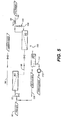
- FIG. 5 illustrates a system and process substantially in accordance with that of Fig. 4, with the provision of a recycle membrane M R in recycle gas line 100. Also provided is a conduit 110 and vacuum pump 112 which allows separation via recycle membrane M R of carrier gases. Thus the recycle gases in conduit 108 are comprised primarily of other process gases as defined herein.
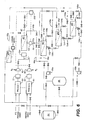
- FIGs. 6 and 7 illustrate two other possible embodiments of the invention.
- several identical or different processes 60...61 are available for use (either simultaneously or not), using similar or different PFC gases and other gases designated as process gases.
- the gas exhausts from 60...61 are preferably scrubbed in scrubbers S 1 , S N , and then are preferably diluted with N 2 , and compressed respectively in 62...63, and mixed together as a single stream 67 (in fact the various processes 1...N may either successively or simultaneously discharge exhaust gases).
- Single stream 67 is then preferably filtered at S m as a final cleaning step, then fed to a membrane unit M1 of the invention wherein the permeate 65 may be vented and a non-permeate 66 and 66a (concentrated PFCs) may be recycled to one or several of the processes 1...N, respectively 60...61.
- non-permeate stream 66c may be routed to one or more membrane units M 2 , M 3 , ... M N , thus improving the purity of the PFCs.
- a sweep gas stream 66b may be employed to sweep the permeate side of M1.
- Membrane units M 2 , M 3 and M N also may have sweep gas streams.
- vacuum pumps 69a and 69b
- high pressure PFC storage vessel 68 and/or a surge tank 64.
- one process may be a metal oxide etch, another might be an oxide etch, and yet another might be a tungsten CVD process.
- a mass flow measurement device 100 on the non-permeate stream 66 of membrane unit M 1 which may be used to control the flow of the permeate stream indirectly via controller 200, which accepts a signal from flow measurement device 100 and adjusts flow control valves in conduits 67 and 65.
- Conduit 66 also preferably includes a backpressure regulator, which is not illustrated for clarity.
- Backpressure regulators 102, 104, ansd 106 serve the function as described above for backpressure regulator 97 (FIG. 4).
- Other process control schemes are certainly feasible. For example, it may be advantageous, as previously mentioned, to operate M 1 using a set point PFC concentration in the non-permeate stream 66.
- the flow measurement device may also include analysis equipment to determine the PFC concentration in conduit 66. Similar process controls may be used for membrane units M1, M2, M3, and MN as desired. Also, similar piping arrangements may be employed in the latter membrane units, as denoted at 108a, 108b, 108c, 104a, 104b, 104c, 106a, 106b, and 106c.
- FIG. 7 is a parallel processing embodiment wherein each process 1...N is associated (after dilution with nitrogen and compression respectively in 72 and 73) with a membrane system M 1 ...M N , respectively, according to the invention.
- Each feed stream 74...75 is fed to a membrane system M 1 ...M N (with pretreatment systems S 1 ...S N if necessary).
- the permeate gases are vented together at 78 while each non-permeate 79, 80 is recycled, preferably to its corresponding process.
- Preferred systems of the invention include a redundant membrane unit M s , preferably having its own pretreatment unit S T .
- a recycle membrane unit M R which separates usable reactive process gases from carrier gases. Note that with suitable arrangement of valves, this embodiment can operate in parallel or series (cascade) mode.
- a pressure drop across the membrane may be created by creating vacuum on the permeate side of the membrane while keeping the feed gas at about atmospheric pressure, which is usually about the pressure of the gas mixture released from the semiconductor manufacturing process.
- atmospheric pressure which is usually about the pressure of the gas mixture released from the semiconductor manufacturing process.
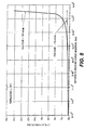
- FIG. 8 illustrates at 20°C for two different flow rates of the feed flow of 170 ml/min and 130 ml/min, respectively, on a hollow-fiber membrane made of polyimide having a surface of about 0.2 m 2 wherein the feed flow is sent into the hollow fiber with a permeation towards the outside hollow fiber.
- FIG. 8 clearly illustrates for low pressure drop between the non-permeate and the permeate sides of the membrane, no concentration of C 2 F 6 occurs (0.2% of C 2 F 6 recovered on the non-permeate side with the "residue").
- the concentration of C 2 F 6 then increases with an onset point of about 7 ⁇ 10 5 N/m 2 ( ⁇ P across the membrane) for a feed flow of 130 ml/min.
- the onset point is obviously higher (increases with feed flow).
- FIG. 9 illustrates the effect of the temperature of the feed flow (or of the membrane)--same membrane as used for FIG. 8. For a higher temperature of the flow, a higher differential pressure across the membrane is needed to achieve the same concentration of PFCs.
- FIG. 10 illustrates the recovery rate of C 2 F 6 on the non-permeate side of the membrane versus the differential pressure across the membrane for two different flow rates: for very low differential pressure, about all of the C 2 F 6 is recovered while the rate of C 2 F 6 permeating through the membrane progressively increases with the pressure drop across the membrane, such rate increasing faster for lower flow rates (compare curves for 130 ml/min. and 170 ml/min).
- FIG. 11 illustrates the effect of temperature for a flow of 170 ml/min.: while only an extremely low amount of C 2 F 6 permeates at 20°C, almost half of it permeates at 55°C for a pressure drop of about 7 ⁇ 10 5 N/m 2 .
- FIGs. 10 and 11 From a recovery standpoint (FIGs. 10 and 11), it is thus better to operate at high flow rates and ambient temperature for a give pressure drop. But FIGs. 8 and 9 indicate that a substantial pressure drop is necessary to have a certain purity of C 2 F 6 (and thus a certain concentration).
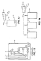
- FIGs 12-14 illustrate another aspect of the invention.
- Gas cabinets (sometimes known as gas panels) are well known in the semiconductor manufacturing art and need little explanation to the skill artisan.
- a gas cabinet for PFCs will have a PFC vent stream.
- the following discussion is for gas cabinet vents, the idea pertains to the recovery of a relatively pure PFC stream from any venting of PFCs.
- All automated gas cabinets employ specific purging routines before and after cylinder change.
- the pre-purge routine generally is utilized to purge process gas while a post-purge routine is generally used to remove purging intrusions.
- the following describes different operational modes of a typical gas cabinet.
- Process gas flows first through V1, then through a pressure reducing regulator and then through V7.
- Valves V2, V3 and V5 are bypassed during the process gas delivery mode.
- the vacuum generator is activated with nitrogen by V4 and the vent line is purged for atmospheric removal.
- the vent area between V2 and V5 is also evacuated at this time.
- V4 is then cycled on and off to back fill the area between V2 and V5 with nitrogen.
- V7 With V7 closed and V4 on, the process gas is vented through V5 and V1 remains open until the process gas safely reaches atmospheric pressure (sensed by a pressure transducer).
- a 0.40" orifice is located on the vacuum inlet of the vacuum generator to restrict the venting flow rate.
- V1 With V4 on, V1 closed and V2 opened, a vacuum of 22-24" Hg is generated between V1 and the cylinder valve. Note: V1 is always closed during the purging routine.
- V6 is opened allowing nitrogen pressure 80 psi) to overcome the vacuum and to pressurize the system with nitrogen between V1 and the cylinder valve.
- V6 is closed, a vacuum is then again generated between V1 and the cylinder valve (Fig. 12d).
- V6 is cycled on and off multiple times in the pre-purge to create the vacuum/pressure purging action.
- a pigtail purge bleed is activated by partially opening V6 while V3 is open. When the process gas cylinder is removed, a pre-set flow of nitrogen will flow from the pigtail preventing atmospheric intrusion.
- V6 is opened allowing nitrogen pressure 80 psi) to overcome the vacuum and to pressurize the system with nitrogen between V1 and the cylinder valve.
- V6 is closed, a vacuum is then again generated between V1 and the cylinder valve (Fig. 12d).
- V6 is cycled on and off multiple times in the pre-purge to create the vacuum/pressure purging action. This sequence ends with the pigtail up to V1 under vacuum.
- the process gas cylinder valve is now opened. V4 is turned on and then V1 is opened. Next V5 is cycled on and off allowing process gas to be flushed through the vent through an orifice. Once this sequence is complete the system returns to the Process Gas Delivery Mode.
- FIG. 13 illustrates schematically the provision a pure PFC stream 120 to a gas cabinet 150 (the internals are not illustrated for clarity).
- Gas cabinet 150 has a vent tube or conduit 180 which leads to a membrane separator unit 200 having a non-permeate stream 220 and a permeate stream 240 as explained herein.
- FIG. 14 illustrates schematically the provision of multiple (in this case three) gas cabinets 150a, 150b, and 150c, all venting into a common membrane recovery unit 200.
- a feed stream comprising 0.95% vol. C 2 F 6 , 1.03% vol. CHF 3 , 1.10% CF 4 , and 96.93% nitrogen at a pressure of 544,218 Pascal, a temperature of 293K (20°C) and a flow rate of 193 sl/m (standard liter per minute) is fed on the feed side of a polyimide membrane made according to USP 5,085,676.
- a vacuum system creates a low pressure on the other side of the membrane: the permeate stream recovered is at a pressure of 6,579 Pascal, a temperature of 293K and a flow rate of 181 sl/m, while on the non-permeate side, the pressure remains 544,218 Pascal, the temperature 293K and the flow rate 12 sl/m.
- the non-permeate (concentrated) stream from the membrane comprises: C 2 F 6 15.66% vol. CHF 3 9.54% vol. CF 4 18.15% vol. N 2 56.65% vol.
- the permeate stream from the membrane comprises: C 2 F 6 0.02% vol. CHF 3 0.48% vol. CF 4 0.01% vol. N 2 99.49% vol.
- the non-permeate stream is further sent to a cryogenic condensation system as disclosed hereabove wherein 0.4942 pound of liquid nitrogen per pound of non-permeate stream is contacted by heat exchange, thus condensing most of the PFCs as indicated hereafter.
- the compositions of the vapor and liquid streams are the following:
- This vapor stream comprises essentially CF 4 diluted in nitrogen.
- the vapor stream is preferably recycled to the input of the cryogenic condensation system or may be treated (for example scrubbed) and discarded.
- a feed stream comprising 0.95% vol. C 2 F 6 , 1.03% vol. CHF 3 , 1.10% CF 4 , and 96.93% nitrogen at a pressure of 5,44.10 5 Pascal, a temperature of 20°C and a flow rate of 193 sl/m (standard liter per minute) is sent on the same membrane as in Example 1, said membrane being connected to the same cryogenic separation system using liquid nitrogen.
- the non-permeate (concentrated) stream from the membrane comprises: C 2 F 6 15.66% vol. CHF 3 9.54% vol. CF 4 18.15% vol. N 2 56.65% vol. at the same temperature and pressure as the feed stream, but at a flowrate of 12 sl/m.
- the permeate stream from the membrane comprises: C 2 F 6 0.02% vol. CHF 3 0.48% vol. CF 4 0.01% vol. N 2 99.49% vol.
- the non-permeate stream is further sent to the cryogenic separation system disclosed in Example 1 and the following vapor and liquid streams are obtained:
- a feed stream comprising 0.20% vol. C 2 F 6 , 0.01% vol. CHF 3 , 0.06% CF 4 , 0.01% NF 3 , 0.01% SF 6 and 99.71% nitrogen at a pressure of 714,286 Pascal, a temperature of 20°C and a flow rate of 199 sl/m (standard liter per minute) is sent on the same membrane as in Example 1, said membrane being connected to the same cryogenic separation system using liquid nitrogen.
- the non-permeate (concentrated) stream from the membrane comprises: C 2 F 6 0.5381% vol. CHF 3 0.02% vol. CF 4 0.1611% vol. NF 3 0.0245% vol. SF 6 0.0271% vol.
- the permeate stream from the membrane comprises: C 2 F 6 0.0041% vol. CHF 3 0.0047% vol. CF 4 0.0014% vol. NF 3 0.0016% vol. SF 6 0.0004% vol. N 2 99.9878% vol.
- the pressure of the permeate is 6579 Pascal with a flow rate of 126 sl/m.
- the non-permeate stream is further sent to the cryogenic separation system disclosed in Example (0.4335 pound of LN 2 for each pound of non-permeate stream) and the following vapor and liquid stream are obtained:
- a feed stream comprising 0.20% vol. C 2 F 6 , 0.01% vol. CHF 3 , 0.06% CF 4 , 0.01% NF 3 , 0.01% SF 6 and 99.71% nitrogen at a pressure of 319,728 Pascal, a temperature of 20°C and a flow rate of 170 sl/m (standard liter per minute) is sent on the same membrane as in Example 1, said membrane being connected to the same cryogenic separation system using liquid nitrogen.
- the non-permeate (concentrated) stream from the membrane comprises: C 2 F 6 0.5600% vol. CHF 3 0.0200% vol. CF 4 0.1700% vol. NF 3 0.0300% vol. SF 6 0.0300% vol. N 2 99.2000% vol. (At the same temperature and pressure than the feed stream, but at a flow rate of 112 sl/m.)
- the permeate stream from the membrane comprises: C 2 F 6 0.0154% vol. CHF 3 0.0041% vol. CF 4 0.0039% vol. NF 3 0.0019% vol. SF 6 0.0009% vol. N 2 99.9738% vol.
- the pressure of the permeate is 6579 Pascal with a flowrate of 112 sl/m.
- the non-permeate stream is further sent to the cryogenic separation system disclosed in Example 1 0.195 kg (0.4335 lb.) of LN 2 for each 0.45 kg (lb.) of non-permeate stream) and the following vapor and liquid stream are obtained:
- a feed stream comprising 1.00% vol. C 2 F 6 , 0.01% vol. CHF 3 , 0.01% CF 4 , and 98.96% nitrogen at a pressure of 866,595 Pascal, a temperature of 20°C and a flow rate of 5,000 sl/m (standard liter per minute) is sent on the same membrane (first membrane) as in Example 1, said membrane being connected to a second membrane (cascade connection: non-permeate side of the first to the feed side of the second).
- the non-permeate (concentrated) stream from the first membrane comprises: C 2 F 6 33.93% vol. CHF 3 0.17% vol. CF 4 0.31% vol. NF 3 0.17% vol. SF 6 0.31% vol. N 2 65.11% vol.
- the non-permeate (concentrated) stream from the first membrane comprises: C 2 F 6 33.93% vol. CHF 3 0.17% vol. CF 4 0.31% vol. NF 3 0.17% vol. SF 6 0.31% vol. N
- the permeate stream from the first membrane comprises: C 2 F 6 0.0012% vol. CHF 3 0.0053% vol. CF 4 0.0009% vol. NF 3 0.0052% vol. SF 6 0.0009% vol. N 2 99.9865% vol.
- the non-permeate (concentrated) stream from the second membrane comprises: C 2 F 6 96.52% vol. CHF 3 0.23% vol. CF 4 0.81% vol. NF 3 0.24% vol. SF 6 0.81% vol. N 2 0.39% vol.
- the permeate stream from the second membrane comprises: C 2 F 6 0.0636% vol. CHF 3 0.1358% vol. CF 4 0.0424% vol. NF 3 0.1339% vol. SF 6 0.0406% vol. N 2 99.58739% vol.
- a feed stream comprising 1.00% vol. C 2 F 6 , 0.2% CF 4 , and 98.9% nitrogen at a pressure of 213,315 Pascal, a temperature of 20°C and a flow rate of 6,366 grams/min. is sent on the same membrane as in Example 1, said membrane being connected to a vacuum switch adsorption system (VSA) with a switching time of 15 min.
- VSA vacuum switch adsorption system
- the non-permeate (concentrated) stream from the membrane comprises: C 2 F 6 74.2% wt. CF 4 10.8% wt. N 2 15.1% wt.
- the permeate stream from the membrane comprises: C 2 F 6 0.001% wt. CF 4 0.014% wt. N 2 99.985% wt.
- the VSA non-adsorbed stream comprises: C 2 F 6 94.9% wt. CF 4 5.1% wt.
- the VSA adsorbed stream comprises: CF 4 30.9% wt. N 2 69.1% wt.
- a system of the invention was used to recover PFCs from an effluent stream from a semiconductor tool.
- a first membrane separation unit included three hollow fiber bundles, while a second membrane separation unit included only one hollow fiber bundle.
- Each hollow fiber bundle was equal in surface area; thus the first membrane unit provided three times the surface area for mass transfer than did the first bundle.
- Each bundle also used the hollow fibers described in Example 1.
- a feed stream comprising 2083 ppm C 2 F 6 , 595 ppm CF4, and balance nitrogen, at a pressure of about 540 kiloPascal, a temperature of 305K (32°C) and a flow rate of 201 scfh, or 95 sl/m (standard liter per minute) was fed on the feed side of a polyimide membrane made according to USP 5,085,676.
- the PFC recovered in the non-permeate from the second membrane was about 0.457 scfh, or 0.216 sl/m, for a PFC recovery of about 99.5%.
Landscapes
- Chemical & Material Sciences (AREA)
- Engineering & Computer Science (AREA)
- Analytical Chemistry (AREA)
- General Chemical & Material Sciences (AREA)
- Oil, Petroleum & Natural Gas (AREA)
- Chemical Kinetics & Catalysis (AREA)
- Organic Chemistry (AREA)
- Separation Using Semi-Permeable Membranes (AREA)
- Treating Waste Gases (AREA)
- Separation Of Gases By Adsorption (AREA)
Applications Claiming Priority (5)
| Application Number | Priority Date | Filing Date | Title |
|---|---|---|---|
| US50332595A | 1995-07-17 | 1995-07-17 | |
| US503325 | 1995-07-17 | ||
| US665142 | 1996-06-14 | ||
| US08/665,142 US5785741A (en) | 1995-07-17 | 1996-06-14 | Process and system for separation and recovery of perfluorocompound gases |
| EP96401575A EP0754487B1 (fr) | 1995-07-17 | 1996-07-16 | Procédé et dispositif pour séparer et récupérer des composés perfluoriques gazeux |
Related Parent Applications (1)
| Application Number | Title | Priority Date | Filing Date |
|---|---|---|---|
| EP96401575A Division EP0754487B1 (fr) | 1995-07-17 | 1996-07-16 | Procédé et dispositif pour séparer et récupérer des composés perfluoriques gazeux |
Publications (2)
| Publication Number | Publication Date |
|---|---|
| EP1287875A2 true EP1287875A2 (fr) | 2003-03-05 |
| EP1287875A3 EP1287875A3 (fr) | 2003-03-12 |
Family
ID=27054462
Family Applications (2)
| Application Number | Title | Priority Date | Filing Date |
|---|---|---|---|
| EP02292630A Withdrawn EP1287875A3 (fr) | 1995-07-17 | 1996-07-16 | Dispositif pour séparer et récupérer des composés perfluoriques gazeux |
| EP96401575A Expired - Lifetime EP0754487B1 (fr) | 1995-07-17 | 1996-07-16 | Procédé et dispositif pour séparer et récupérer des composés perfluoriques gazeux |
Family Applications After (1)
| Application Number | Title | Priority Date | Filing Date |
|---|---|---|---|
| EP96401575A Expired - Lifetime EP0754487B1 (fr) | 1995-07-17 | 1996-07-16 | Procédé et dispositif pour séparer et récupérer des composés perfluoriques gazeux |
Country Status (7)
| Country | Link |
|---|---|
| US (4) | US5785741A (fr) |
| EP (2) | EP1287875A3 (fr) |
| JP (1) | JP3151151B2 (fr) |
| KR (1) | KR100266460B1 (fr) |
| CN (3) | CN101538016A (fr) |
| DE (1) | DE69629769T2 (fr) |
| SG (1) | SG54348A1 (fr) |
Cited By (2)
| Publication number | Priority date | Publication date | Assignee | Title |
|---|---|---|---|---|
| DE102013219366A1 (de) * | 2013-09-26 | 2015-03-26 | Siemens Aktiengesellschaft | Verfahren zum Abtrennen von Fremdstoffen aus einem Gemisch, enthaltend ein fluides Arbeitsmedium und entsprechende Fremdstoffe |
| CN108905498A (zh) * | 2018-07-05 | 2018-11-30 | 吴亚琴 | 一种利用废弃玻璃制备空气净化材料载体的方法 |
Families Citing this family (107)
| Publication number | Priority date | Publication date | Assignee | Title |
|---|---|---|---|---|
| US5785741A (en) | 1995-07-17 | 1998-07-28 | L'air Liquide, Societe Anonyme Pour L'etude Et L'exploitation Des Procedes Georges, Claude | Process and system for separation and recovery of perfluorocompound gases |
| JPH0929002A (ja) * | 1995-07-17 | 1997-02-04 | Teisan Kk | ガス回収装置 |
| US5858065A (en) * | 1995-07-17 | 1999-01-12 | American Air Liquide | Process and system for separation and recovery of perfluorocompound gases |
| IE80909B1 (en) * | 1996-06-14 | 1999-06-16 | Air Liquide | An improved process and system for separation and recovery of perfluorocompound gases |
| US6888040B1 (en) * | 1996-06-28 | 2005-05-03 | Lam Research Corporation | Method and apparatus for abatement of reaction products from a vacuum processing chamber |
| FR2751565B1 (fr) * | 1996-07-26 | 1998-09-04 | Air Liquide | Procede et installation de traitement de gaz perfluores et hydrofluorocarbones en vue de leur destruction |
| US5730779A (en) * | 1996-10-31 | 1998-03-24 | Air Products And Chemicals, Inc. | Fluorochemical recovery and recycle using membranes |
| US5814127A (en) * | 1996-12-23 | 1998-09-29 | American Air Liquide Inc. | Process for recovering CF4 and C2 F6 from a gas |
| KR100217499B1 (ko) * | 1996-12-24 | 1999-09-01 | 윤종용 | 반도체설비 환경분석용 이온크로마토그래피 시스템 |
| CA2275960A1 (fr) * | 1997-01-23 | 1998-07-30 | Gil Dagan | Recuperation de composes perfluores et membranes a tamis moleculaire mettant en oeuvre des gaz hydrofluorocarbones |
| US5779763A (en) * | 1997-03-07 | 1998-07-14 | Membrane Technology And Research, Inc. | Process for recovering semiconductor industry cleaning compounds |
| US6123749A (en) * | 1997-05-02 | 2000-09-26 | E. I. Du Pont De Nemours And Company | Separation of CO2 from unsaturated fluorinated compounds by semipermeable membrane |
| DE69823182T2 (de) * | 1997-05-02 | 2005-04-21 | Du Pont | Entfernung von co2 aus fluorkohlenwasserstoffen durch semipermeable membrane |
| US5843208A (en) * | 1997-07-24 | 1998-12-01 | Alliedsignal Inc. | Process for recovering sulfur hexafluoride |
| EP0908219B1 (fr) * | 1997-10-09 | 1999-12-08 | Gkss-Forschungszentrum Geesthacht Gmbh | Procédé à plusieurs étapes de séparation/récuperation de gaz |
| CA2316346A1 (fr) | 1997-12-31 | 1999-07-08 | Eric C. Hilton | Capture des particules contenant du germanium dans les gaz d'emission d'un systeme de production de verre |
| US6866094B2 (en) * | 1997-12-31 | 2005-03-15 | Temptronic Corporation | Temperature-controlled chuck with recovery of circulating temperature control fluid |
| AU7431198A (en) * | 1998-01-16 | 1999-08-02 | L'air Liquide, Societe Anonyme Pour L'etude Et L'exploitation Des Procedes Georges Claude | Process and system for separation and recovery of perfluorocompound gases |
| JPH11218318A (ja) * | 1998-02-03 | 1999-08-10 | Air Liquide Japan Ltd | 排ガス処理設備 |
| US5976222A (en) * | 1998-03-23 | 1999-11-02 | Air Products And Chemicals, Inc. | Recovery of perfluorinated compounds from the exhaust of semiconductor fabs using membrane and adsorption in series |
| US6032484A (en) * | 1998-03-23 | 2000-03-07 | Air Products And Chemicals, Inc. | Recovery of perfluorinated compounds from the exhaust of semiconductor fabs with recycle of vacuum pump diluent |
| US6017382A (en) * | 1998-03-30 | 2000-01-25 | The Boc Group, Inc. | Method of processing semiconductor manufacturing exhaust gases |
| US6187077B1 (en) * | 1998-04-17 | 2001-02-13 | American Air Liquide Inc. | Separation of CF4 and C2F6 from a perfluorocompound mixture |
| FR2779070B1 (fr) * | 1998-05-28 | 2000-06-30 | Air Liquide | Dispositif de fourniture d'un gaz epure a une installation purgee avec ce gaz epure |
| DE19910678A1 (de) * | 1998-08-20 | 2000-09-14 | Solvay Fluor & Derivate | Verfahren zur Reinigung von SF¶6¶-kontaminierten Gasen |
| JP2000185212A (ja) * | 1998-12-22 | 2000-07-04 | Ube Ind Ltd | パーフルオロ化合物ガスの分離回収方法および装置 |
| US6076372A (en) * | 1998-12-30 | 2000-06-20 | Praxair Technology, Inc. | Variable load refrigeration system particularly for cryogenic temperatures |
| US6881354B2 (en) | 1998-12-30 | 2005-04-19 | Praxair Technology, Inc. | Multicomponent refrigerant fluids for low and cryogenic temperatures |
| SG80623A1 (en) * | 1999-04-26 | 2001-05-22 | Air Prod & Chem | Recovery of perfluorinated compounds from the exhaust of semiconductor fabs using membrane and adsorption in series |
| DE19923155A1 (de) * | 1999-05-20 | 2000-11-23 | Solvay Fluor & Derivate | SF¶6¶-Abtrennung aus Isoliergasen aus gasisolierten Leitungen |
| US6238462B1 (en) | 1999-07-14 | 2001-05-29 | Corning Incorporated | Methods for the separation of compounds from acidic aqueous solutions |
| US6689252B1 (en) | 1999-07-28 | 2004-02-10 | Applied Materials, Inc. | Abatement of hazardous gases in effluent |
| US6468490B1 (en) * | 2000-06-29 | 2002-10-22 | Applied Materials, Inc. | Abatement of fluorine gas from effluent |
| FR2798076B1 (fr) * | 1999-09-06 | 2002-05-24 | Air Liquide | Procede d'elimination par permeation des composes fluores ou fluorosoufres d'un flux de xenon et/ou de krypton |
| JP4357046B2 (ja) * | 1999-10-01 | 2009-11-04 | 株式会社東芝 | ガス回収装置 |
| JP2001104702A (ja) * | 1999-10-01 | 2001-04-17 | Air Liquide Japan Ltd | ガスの集合回収装置および集合回収方法 |
| US6391385B1 (en) * | 1999-10-18 | 2002-05-21 | Advanced Technology Materials, Inc. | Method of abating of effluents from chemical vapor deposition processes using organometallic source reagents |
| US6491884B1 (en) | 1999-11-26 | 2002-12-10 | Advanced Technology Materials, Inc. | In-situ air oxidation treatment of MOCVD process effluent |
| JP4018858B2 (ja) | 1999-12-20 | 2007-12-05 | 大同エアプロダクツ・エレクトロニクス株式会社 | パーフルオロ化合物分離回収方法およびそれに用いるパーフルオロ化合物分離回収装置 |
| SG106599A1 (en) * | 2000-02-01 | 2004-10-29 | Tokyo Electron Ltd | Substrate processing apparatus and substrate processing method |
| WO2001062366A1 (fr) * | 2000-02-22 | 2001-08-30 | Solvay Fluor Und Derivate Gmbh | Separation de gaz contenant sf¿6? |
| US6863019B2 (en) * | 2000-06-13 | 2005-03-08 | Applied Materials, Inc. | Semiconductor device fabrication chamber cleaning method and apparatus with recirculation of cleaning gas |
| JP2002035528A (ja) * | 2000-07-26 | 2002-02-05 | Japan Atom Energy Res Inst | ガス分離装置 |
| JP2002035527A (ja) * | 2000-07-26 | 2002-02-05 | Japan Atom Energy Res Inst | ガス分離装置 |
| JP4089223B2 (ja) * | 2001-12-26 | 2008-05-28 | 宇部興産株式会社 | ハロゲン化合物ガスの分離回収装置および分離回収方法 |
| US6921428B2 (en) * | 2001-01-25 | 2005-07-26 | Ube Industries, Ltd. | Device and method for separating and collecting halide gas |
| US20020134530A1 (en) * | 2001-03-20 | 2002-09-26 | American Air Liquide, Inc. | Heat transfer fluids and methods of making and using same |
| US20020129622A1 (en) * | 2001-03-15 | 2002-09-19 | American Air Liquide, Inc. | Heat transfer fluids and methods of making and using same |
| JP4211227B2 (ja) * | 2001-03-16 | 2009-01-21 | 株式会社日立製作所 | 過弗化物の処理方法及びその処理装置 |
| US6602323B2 (en) | 2001-03-21 | 2003-08-05 | Samsung Electronics Co., Ltd. | Method and apparatus for reducing PFC emission during semiconductor manufacture |
| US6668582B2 (en) | 2001-04-20 | 2003-12-30 | American Air Liquide | Apparatus and methods for low pressure cryogenic cooling |
| US6651358B2 (en) | 2001-04-30 | 2003-11-25 | American Air Liquide, Inc. | Heat transfer fluids and methods of making and using same comprising hydrogen, helium and combinations thereof |
| US6574972B2 (en) | 2001-04-30 | 2003-06-10 | L'air Liquide - Societe' Anonyme A' Directoire Et Conseil De Surveillance Pour L'etude Et L'exploitation Des Procedes Georges Claude | Low temperature heat transfer methods |
| JP2003068630A (ja) * | 2001-08-29 | 2003-03-07 | Kyocera Corp | 露光装置 |
| FR2829403B1 (fr) * | 2001-09-11 | 2003-12-12 | Air Liquide | Procede de production par permeation, a partir d'un melange gazeux, d'au moins deux flux gazeux et installation de mise en oeuvre d'un tel procede |
| KR100592981B1 (ko) * | 2002-01-21 | 2006-06-23 | 주식회사 셈테크놀러지 | 하이브리드형 유해가스 폐기 시스템 및 방법 |
| JP2003286012A (ja) * | 2002-03-28 | 2003-10-07 | Toshiba Corp | ガスリサイクルシステムおよび方法、ガス絶縁機器、六弗化硫黄供給システム並びに電力事業システム |
| JP4214717B2 (ja) * | 2002-05-31 | 2009-01-28 | 株式会社日立製作所 | 過弗化物処理装置 |
| US6960242B2 (en) * | 2002-10-02 | 2005-11-01 | The Boc Group, Inc. | CO2 recovery process for supercritical extraction |
| US20040187683A1 (en) * | 2003-03-28 | 2004-09-30 | Luping Wang | Gas recovery system to improve the efficiency of abatementand/or implement reuse/reclamation |
| US6843830B2 (en) * | 2003-04-15 | 2005-01-18 | Advanced Technology Materials, Inc. | Abatement system targeting a by-pass effluent stream of a semiconductor process tool |
| US20050011442A1 (en) * | 2003-06-24 | 2005-01-20 | International Business Machines Corporation | Plasma processing material reclamation and reuse |
| US7329308B2 (en) * | 2003-07-09 | 2008-02-12 | Entegris, Inc. | Air handling and chemical filtration system and method |
| US20050096490A1 (en) * | 2003-10-29 | 2005-05-05 | Henderson Philip B. | Purification of perfluoromethane |
| JP4415656B2 (ja) * | 2003-11-26 | 2010-02-17 | ダイキン工業株式会社 | 二フッ化カルボニルの精製方法 |
| US7569193B2 (en) | 2003-12-19 | 2009-08-04 | Applied Materials, Inc. | Apparatus and method for controlled combustion of gaseous pollutants |
| US20050211097A1 (en) * | 2004-03-26 | 2005-09-29 | Thomas Eckman | Apparatus for permeate side sweep of fiber membrane permeators |
| KR100819653B1 (ko) * | 2004-03-31 | 2008-04-07 | 다이킨 고교 가부시키가이샤 | 기체 정화 장치 |
| US7736599B2 (en) | 2004-11-12 | 2010-06-15 | Applied Materials, Inc. | Reactor design to reduce particle deposition during process abatement |
| TWI251301B (en) * | 2004-11-29 | 2006-03-11 | Unimicron Technology Corp | Substrate core and method for fabricating the same |
| JP4724877B2 (ja) * | 2005-01-28 | 2011-07-13 | 独立行政法人物質・材料研究機構 | 炭素多孔体、炭素多孔体を製造する方法、吸着剤および生体分子素子 |
| US7264013B2 (en) * | 2005-05-13 | 2007-09-04 | Air Products And Chemicals, Inc. | Enhanced purge effect in gas conduit |
| CN101300411B (zh) | 2005-10-31 | 2012-10-03 | 应用材料公司 | 制程减降反应器 |
| US7628845B2 (en) * | 2006-03-10 | 2009-12-08 | Macronix International Co., Ltd. | Filtering device and filtering method thereof and semiconductor fabricating method |
| US8002025B2 (en) * | 2006-04-28 | 2011-08-23 | International Business Machines Corporation | Containment of a wafer-chuck thermal interface fluid |
| US7604681B2 (en) * | 2006-05-26 | 2009-10-20 | Lummus Technology, Inc. | Three-stage membrane gas separation process |
| US20080034970A1 (en) * | 2006-08-10 | 2008-02-14 | Frank Jansen | Sulfur hexafluoride recycling system and method for recycling sulfur hexafluoride |
| GB0618016D0 (en) * | 2006-09-13 | 2006-10-18 | Boc Group Plc | Method of recycling hydrogen |
| US7767000B1 (en) * | 2007-03-29 | 2010-08-03 | The United States Of America As Represented By The United States Department Of Energy | Regenerable hydrogen chloride removal sorbent and regenerable multi-functional hydrogen sulfide and hydrogen chloride removal sorbent for high temperature gas streams |
| JP4280782B2 (ja) * | 2007-04-10 | 2009-06-17 | 東京エレクトロン株式会社 | 半導体製造装置のガス供給システム |
| AR066468A1 (es) | 2007-05-09 | 2009-08-19 | Shell Int Research | Un catalizador de epoxidacion, un proceso para preparar el mismo, y un proceso para producir un oxido de olefina , un 1,2- diol, un 1,2 - diol eter, un 1,2- carbonato, o una alcanolamina |
| US7572976B1 (en) * | 2008-02-06 | 2009-08-11 | Victor Merrill | Quick connect electrical box |
| FR2933714B1 (fr) * | 2008-07-11 | 2011-05-06 | Air Liquide | Procede de recyclage de silane (sih4) |
| US20090320519A1 (en) * | 2008-06-30 | 2009-12-31 | American Air Liquide, Inc. | Recovery of Hydrofluoroalkanes |
| JP4850223B2 (ja) * | 2008-09-10 | 2012-01-11 | 積水化学工業株式会社 | プラズマ処理方法及び装置 |
| US8192529B2 (en) * | 2009-03-10 | 2012-06-05 | Gatton Jr Lawrence H | Integrated dry scrubber system |
| US8648293B2 (en) * | 2009-07-08 | 2014-02-11 | Agilent Technologies, Inc. | Calibration of mass spectrometry systems |
| IT1400850B1 (it) * | 2009-07-08 | 2013-07-02 | Varian Spa | Apparecchiatura di analisi gc-ms. |
| DE102010012601A1 (de) * | 2010-03-24 | 2011-09-29 | Siemens Aktiengesellschaft | Vorrichtung und Verfahren zum Trennen eines fluiden Stoffgemisches |
| TW201216397A (en) * | 2010-07-30 | 2012-04-16 | Jx Nippon Oil & Amp Energy Corp | Discharge gas treating system |
| US8812179B1 (en) | 2010-10-05 | 2014-08-19 | The Boeing Company | Ammonia detection |
| KR101410914B1 (ko) * | 2012-02-23 | 2014-06-24 | (주)파인텍 | 과불화화합물의 분리 및 재활용시스템 |
| KR101410712B1 (ko) * | 2012-02-23 | 2014-06-24 | (주)파인텍 | 과불화화합물의 분리 및 재활용시스템 |
| CN104797322B (zh) * | 2012-11-14 | 2016-12-14 | 赢创纤维有限公司 | 采用膜的气体分离装置的气体组成控制 |
| KR101514801B1 (ko) * | 2013-06-25 | 2015-04-24 | (주)파인텍 | 과불화화합물의 분리 및 재활용시스템 |
| WO2015006258A1 (fr) * | 2013-07-12 | 2015-01-15 | Arkema Inc. | Procédé de séparation de composés organofluorés à l'aide d'une membrane |
| KR101676099B1 (ko) * | 2014-09-24 | 2016-11-15 | 오씨아이 주식회사 | Nf3 가스 분리농축 방법, 장치 및 시스템 |
| FR3026314B1 (fr) * | 2014-09-26 | 2019-04-12 | Air Liquide Electronics Systems | Procede de concentration de composes fluores |
| CN106211790B (zh) | 2015-03-26 | 2018-06-22 | 韩国能源技术研究院 | 用于难分解性有害气体焚烧处理的节能型燃烧装置及其方法 |
| TW201733915A (zh) * | 2015-11-13 | 2017-10-01 | 艾克頌美孚研究工程公司 | 逆滲透膜及分離 |
| KR101833882B1 (ko) * | 2015-12-10 | 2018-03-05 | (주)에어레인 | 고선택도의 중공사막 모듈을 포함하는 다단 기체분리공정을 이용한 불화가스 분리방법 |
| EP3695897A1 (fr) | 2019-02-12 | 2020-08-19 | Haffmans B.V. | Système et procédé de séparation d'un mélange gazeux |
| EP3797857A1 (fr) * | 2019-09-30 | 2021-03-31 | General Electric Technology GmbH | Procédé et appareil pour le recyclage de l'heptafluoroisobutyronitrile |
| US11285434B2 (en) * | 2020-03-30 | 2022-03-29 | Air Products And Chemicals, Inc. | Membrane process and system for high recovery of a nonpermeating gas |
| KR102546586B1 (ko) * | 2021-04-22 | 2023-06-22 | (주)세미코 | 사출압력이 일정하게 유지되는 고압 다이캐스팅 주조기 |
| CN114823326B (zh) * | 2022-03-30 | 2023-09-12 | 宿州伊维特新材料有限公司 | 一种利用高纯六氟乙烷进行半导体刻蚀的方法 |
| US12383862B2 (en) | 2023-03-28 | 2025-08-12 | International Business Machines Corporation | Gas stream enrichment using silicone separator cascades |
Family Cites Families (85)
| Publication number | Priority date | Publication date | Assignee | Title |
|---|---|---|---|---|
| US2947687A (en) * | 1954-10-29 | 1960-08-02 | American Oil Co | Separation of hydrocarbons by permeation membrane |
| US2953502A (en) * | 1955-05-24 | 1960-09-20 | American Oil Co | Separation of azeotropic mixtures |
| US2960462A (en) * | 1957-09-30 | 1960-11-15 | American Oil Co | Dual film combinations for membrane permeation |
| US2970106A (en) * | 1958-01-31 | 1961-01-31 | American Oil Co | Aromatic separation process |
| US3508994A (en) * | 1966-07-07 | 1970-04-28 | Dorr Oliver Inc | Method for producing membrane separation devices |
| US3648845A (en) * | 1969-09-02 | 1972-03-14 | Us Interior | Thin film separation membranes and processes for making same |
| US3616607A (en) * | 1970-04-06 | 1971-11-02 | Northern Natural Gas Co | Separation of nitrogen and methane containing gas mixtures |
| DE2248818C2 (de) * | 1972-10-05 | 1981-10-15 | Bayer Ag, 5090 Leverkusen | Dünne porenfreie Polycarbonatfolien und -filme |
| US4113628A (en) * | 1974-06-05 | 1978-09-12 | E. I. Du Pont De Nemours And Company | Asymmetric polyimide membranes |
| JPS5263178A (en) * | 1975-11-17 | 1977-05-25 | Toshiba Corp | Gas separation unit |
| US4192824A (en) * | 1976-09-23 | 1980-03-11 | Coal Industry (Patents) Limited | Aromatic hydrocarbon resins |
| US5064447A (en) * | 1976-11-19 | 1991-11-12 | E. I. Du Pont De Nemours And Company | Process for recovering organic vapors from air |
| US4132824A (en) * | 1977-07-21 | 1979-01-02 | General Electric Company | Method for casting ultrathin methylpentene polymer membranes |
| US4156597A (en) * | 1977-09-23 | 1979-05-29 | General Electric Company | Ultrathin polyetherimide membrane and gas separation process |
| US4155793A (en) * | 1977-11-21 | 1979-05-22 | General Electric Company | Continuous preparation of ultrathin polymeric membrane laminates |
| US4178224A (en) * | 1978-01-19 | 1979-12-11 | Texas Instruments Incorporated | Apparatus for generation and control of dopant and reactive gases |
| DE3062739D1 (en) * | 1979-07-26 | 1983-05-19 | Ube Industries | Process for preparing aromatic polyimide semipermeable membranes |
| JPS57167414A (en) * | 1981-04-03 | 1982-10-15 | Ube Ind Ltd | Production of polyimide hollow fiber |
| JPS57170936A (en) * | 1981-04-14 | 1982-10-21 | Ube Ind Ltd | Preparation of porous polyimide film |
| GB2101137B (en) * | 1981-04-14 | 1984-09-26 | Ube Industries | Producing porous aromatic imide polymer membranes |
| JPS57209607A (en) * | 1981-06-22 | 1982-12-23 | Ube Ind Ltd | Preparation of polyimide separation film |
| JPS5895541A (ja) * | 1981-11-30 | 1983-06-07 | Mitsubishi Chem Ind Ltd | 気体分離膜 |
| US4424067A (en) * | 1982-07-29 | 1984-01-03 | Allied Corporation | Purification of anhydrous hydrogen fluoride |
| JPS5949822A (ja) * | 1982-09-14 | 1984-03-22 | Nippon Sanso Kk | 揮発性無機水素化物等を含有するガスの処理方法 |
| JPS59160506A (ja) * | 1983-02-28 | 1984-09-11 | Kuraray Co Ltd | 複合中空糸分離膜およびその製造法 |
| JPS6135803A (ja) * | 1984-07-26 | 1986-02-20 | Shin Etsu Chem Co Ltd | 複合中空糸 |
| US4553983A (en) | 1984-07-31 | 1985-11-19 | Membrane Technology And Research, Inc. | Process for recovering organic vapors from air |
| US4602922A (en) * | 1984-11-09 | 1986-07-29 | Research Foundation Of State University Of New York | Method of making membranes for gas separation and the composite membranes |
| JPS61187918A (ja) * | 1985-02-18 | 1986-08-21 | Asahi Chem Ind Co Ltd | ドライ・エツチング方法 |
| US4743435A (en) * | 1985-03-13 | 1988-05-10 | Japan Pionics., Ltd. | Method for cleaning exhaust gases |
| US4741829A (en) * | 1985-06-27 | 1988-05-03 | Mitsubishi Rayon Co., Ltd. | Composite hollow fibers and method of making same |
| JPS621404A (ja) * | 1985-06-27 | 1987-01-07 | Mitsubishi Rayon Co Ltd | 多層複合中空繊維状膜及びその製造法 |
| EP0239190A2 (fr) * | 1986-01-23 | 1987-09-30 | Sensidyne Inc. | Procédé et cellule électrochimique pour détecter des hydrures et des vapeurs d'hydrures |
| DE3782120T2 (de) * | 1986-08-15 | 1993-02-11 | Permea Inc | Asymmetrische gastrennungsmembranen, deren haut einen dichtegradienten aufweisen. |
| US4717394A (en) * | 1986-10-27 | 1988-01-05 | E. I. Du Pont De Nemours And Company | Polyimide gas separation membranes |
| US4701187A (en) * | 1986-11-03 | 1987-10-20 | Air Products And Chemicals, Inc. | Process for separating components of a gas stream |
| EP0294142B1 (fr) * | 1987-06-01 | 1992-03-25 | Japan Pionics., Ltd. | Procédé pour purifier de gaz d'échappement |
| US4756932A (en) * | 1987-06-11 | 1988-07-12 | Air Products And Chemicals, Inc. | Process for making highly permeable coated composite hollow fiber membranes |
| US4826599A (en) * | 1987-07-10 | 1989-05-02 | Union Carbide Corporation | Composite membranes and their manufacture and use |
| DE3869301D1 (de) * | 1987-08-31 | 1992-04-23 | Japan Pionics | Methode zum reinigen von giftige komponenten enthaltendem gas. |
| US5009869A (en) * | 1987-12-28 | 1991-04-23 | Electrocinerator Technologies, Inc. | Methods for purification of air |
| US4881953A (en) * | 1988-09-15 | 1989-11-21 | Union Carbide Corporation | Prevention of membrane degradation |
| US4906256A (en) | 1989-03-23 | 1990-03-06 | Membrane Technology & Research, Inc. | Membrane process for treatment of fluorinated hydrocarbon-laden gas streams |
| US4957513A (en) * | 1989-05-10 | 1990-09-18 | Raytheon Company | Method of purifying a mixed H2 /H2 Se vapor stream |
| JP3027606B2 (ja) * | 1989-06-15 | 2000-04-04 | デユポン・カナダ・インコーポレーテツド | パーフルオロジオキソール膜 |
| US4988371A (en) * | 1989-09-12 | 1991-01-29 | The Dow Chemical Company | Novel alicyclic polyimide gas separation membranes |
| US4941893B1 (en) * | 1989-09-19 | 1996-07-30 | Advanced Silicon Materials Inc | Gas separation by semi-permeable membranes |
| FR2652280B1 (fr) * | 1989-09-22 | 1991-11-29 | Air Liquide | Procede d'elimination d'hydrures gazeux sur support solide a base d'oxydes metalliques. |
| JP2745768B2 (ja) | 1990-03-31 | 1998-04-28 | 宇部興産株式会社 | 非対称性分離膜及び浸透気化分離法 |
| JP2841698B2 (ja) * | 1990-05-08 | 1998-12-24 | 宇部興産株式会社 | 低級アルコールの分離法 |
| US5182088A (en) * | 1990-09-07 | 1993-01-26 | L'air Liquide, Societe Anonyme Pour L'etude Et L'exploitation Des Procedes Georges Claude | Removal of gaseous hydrides |
| US5085676A (en) * | 1990-12-04 | 1992-02-04 | E. I. Du Pont De Nemours And Company | Novel multicomponent fluid separation membranes |
| US5256295A (en) * | 1990-12-28 | 1993-10-26 | Membrane Technology & Research | Two-stage membrane process and apparatus |
| US5256296A (en) | 1990-12-28 | 1993-10-26 | Membrane Technology & Research | Membrane process and apparatus for removing a component from a fluid stream |
| JPH04322716A (ja) * | 1991-04-22 | 1992-11-12 | Asahi Chem Ind Co Ltd | ガス除湿方法 |
| US5383957A (en) * | 1991-07-02 | 1995-01-24 | L'air Liquide | Multistage cascade sweep-process for membrane gas separation |
| US5240471A (en) * | 1991-07-02 | 1993-08-31 | L'air Liquide | Multistage cascade-sweep process for membrane gas separation |
| US5226932A (en) * | 1991-10-07 | 1993-07-13 | Praxair Technology, Inc. | Enhanced meambrane gas separations |
| US5196616A (en) * | 1991-10-18 | 1993-03-23 | E. I. Du Pont De Nemours And Company | Process for separating and recovering fluorocarbons and hydrogen fluoride from mixtures thereof |
| US5290341A (en) * | 1992-08-26 | 1994-03-01 | L'air Liquide, Societe Anonyme Pour L'etude Et L'exploitation Des Procedes Georges Claude | Fast response membrane generator using heat accumulation |
| FR2695568B1 (fr) * | 1992-09-14 | 1994-10-21 | Air Liquide | Procédé et installation de séparation de gaz par perméation. |
| US5281255A (en) * | 1992-11-04 | 1994-01-25 | Membrane Technology And Research, Inc | Gas-separation process |
| US5281253A (en) * | 1993-01-06 | 1994-01-25 | Praxair Technology, Inc. | Multistage membrane control system and process |
| US5282964A (en) * | 1993-02-19 | 1994-02-01 | The Dow Chemical Company | Boreside feed hollow fiber membrane device |
| JP2874741B2 (ja) | 1993-03-02 | 1999-03-24 | 宇部興産株式会社 | 非対称性中空糸ポリイミド気体分離膜 |
| US5288304A (en) * | 1993-03-30 | 1994-02-22 | The University Of Texas System | Composite carbon fluid separation membranes |
| DE69319929T2 (de) * | 1993-04-07 | 1999-04-29 | Lovesgrove Research Ltd., Machynlleth, Powys | Tierfutter |
| US5282969A (en) * | 1993-04-29 | 1994-02-01 | Permea, Inc. | High pressure feed membrane separation process |
| US5383956A (en) * | 1993-10-12 | 1995-01-24 | Praxair Technology, Inc. | Start-up and shut down processes for membrane systems and membrane systems useful for the same |
| US5468430A (en) | 1994-05-19 | 1995-11-21 | L'air Liquide S.A. | Process of making multicomponent or asymmetric gas separation membranes |
| EP0682977A3 (fr) * | 1994-05-20 | 2000-01-12 | L'air Liquide, Societe Anonyme Pour L'etude Et L'exploitation Des Procedes Georges Claude | Membrane polymère |
| FR2724327B1 (fr) | 1994-09-12 | 1996-10-25 | Air Liquide | Procede de separation membranaire par cascade de membranes de selectivites differentes |
| US5858065A (en) | 1995-07-17 | 1999-01-12 | American Air Liquide | Process and system for separation and recovery of perfluorocompound gases |
| US5785741A (en) * | 1995-07-17 | 1998-07-28 | L'air Liquide, Societe Anonyme Pour L'etude Et L'exploitation Des Procedes Georges, Claude | Process and system for separation and recovery of perfluorocompound gases |
| US5858066A (en) | 1995-09-22 | 1999-01-12 | E. I. Du Pont De Nemours And Company | Process for separating and recovering fluorocarbons and HCI from gaseous mixtures thereof |
| US5759237A (en) * | 1996-06-14 | 1998-06-02 | L'air Liquide Societe Anonyme Pour L'etude Et, L'exploitation Des Procedes Georges Claude | Process and system for selective abatement of reactive gases and recovery of perfluorocompound gases |
| IE80909B1 (en) | 1996-06-14 | 1999-06-16 | Air Liquide | An improved process and system for separation and recovery of perfluorocompound gases |
| US5730779A (en) | 1996-10-31 | 1998-03-24 | Air Products And Chemicals, Inc. | Fluorochemical recovery and recycle using membranes |
| US5814127A (en) | 1996-12-23 | 1998-09-29 | American Air Liquide Inc. | Process for recovering CF4 and C2 F6 from a gas |
| JP3284335B2 (ja) | 1996-12-27 | 2002-05-20 | 富士通株式会社 | プラズマディスプレイユニット搬送方法 |
| US5779763A (en) | 1997-03-07 | 1998-07-14 | Membrane Technology And Research, Inc. | Process for recovering semiconductor industry cleaning compounds |
| US5855647A (en) | 1997-05-15 | 1999-01-05 | American Air Liquide, Inc. | Process for recovering SF6 from a gas |
| US5843208A (en) | 1997-07-24 | 1998-12-01 | Alliedsignal Inc. | Process for recovering sulfur hexafluoride |
| US6032484A (en) | 1998-03-23 | 2000-03-07 | Air Products And Chemicals, Inc. | Recovery of perfluorinated compounds from the exhaust of semiconductor fabs with recycle of vacuum pump diluent |
| US5976222A (en) * | 1998-03-23 | 1999-11-02 | Air Products And Chemicals, Inc. | Recovery of perfluorinated compounds from the exhaust of semiconductor fabs using membrane and adsorption in series |
-
1996
- 1996-06-14 US US08/665,142 patent/US5785741A/en not_active Expired - Fee Related
- 1996-07-10 SG SG1996010241A patent/SG54348A1/en unknown
- 1996-07-15 KR KR1019960028489A patent/KR100266460B1/ko not_active Expired - Lifetime
- 1996-07-16 DE DE69629769T patent/DE69629769T2/de not_active Expired - Fee Related
- 1996-07-16 CN CNA2009100016121A patent/CN101538016A/zh active Pending
- 1996-07-16 CN CN96110278A patent/CN1150057A/zh active Pending
- 1996-07-16 EP EP02292630A patent/EP1287875A3/fr not_active Withdrawn
- 1996-07-16 EP EP96401575A patent/EP0754487B1/fr not_active Expired - Lifetime
- 1996-07-17 JP JP18787796A patent/JP3151151B2/ja not_active Expired - Lifetime
-
1998
- 1998-07-21 US US09/119,453 patent/US6214089B1/en not_active Expired - Fee Related
-
2000
- 2000-03-28 US US09/536,687 patent/US6254666B1/en not_active Expired - Fee Related
- 2000-09-22 CN CNB001287915A patent/CN1148250C/zh not_active Expired - Lifetime
-
2001
- 2001-01-25 US US09/768,262 patent/US6444011B2/en not_active Expired - Fee Related
Cited By (2)
| Publication number | Priority date | Publication date | Assignee | Title |
|---|---|---|---|---|
| DE102013219366A1 (de) * | 2013-09-26 | 2015-03-26 | Siemens Aktiengesellschaft | Verfahren zum Abtrennen von Fremdstoffen aus einem Gemisch, enthaltend ein fluides Arbeitsmedium und entsprechende Fremdstoffe |
| CN108905498A (zh) * | 2018-07-05 | 2018-11-30 | 吴亚琴 | 一种利用废弃玻璃制备空气净化材料载体的方法 |
Also Published As
| Publication number | Publication date |
|---|---|
| DE69629769D1 (de) | 2003-10-09 |
| JPH09103633A (ja) | 1997-04-22 |
| DE69629769T2 (de) | 2004-08-05 |
| US6444011B2 (en) | 2002-09-03 |
| CN101538016A (zh) | 2009-09-23 |
| KR100266460B1 (ko) | 2000-09-15 |
| EP0754487A1 (fr) | 1997-01-22 |
| US6214089B1 (en) | 2001-04-10 |
| US5785741A (en) | 1998-07-28 |
| JP3151151B2 (ja) | 2001-04-03 |
| US20010029841A1 (en) | 2001-10-18 |
| CN1148250C (zh) | 2004-05-05 |
| KR970005368A (ko) | 1997-02-19 |
| CN1150057A (zh) | 1997-05-21 |
| EP0754487B1 (fr) | 2003-09-03 |
| US6254666B1 (en) | 2001-07-03 |
| CN1304779A (zh) | 2001-07-25 |
| SG54348A1 (en) | 1998-11-16 |
| EP1287875A3 (fr) | 2003-03-12 |
Similar Documents
| Publication | Publication Date | Title |
|---|---|---|
| US5785741A (en) | Process and system for separation and recovery of perfluorocompound gases | |
| US6605133B1 (en) | Process and system for separation and recovery of perfluorocompound gases | |
| EP0853970B1 (fr) | Procédé amélioré pour la séparation et la récupération de composés perfluorés gazeux | |
| US5759237A (en) | Process and system for selective abatement of reactive gases and recovery of perfluorocompound gases | |
| US5976222A (en) | Recovery of perfluorinated compounds from the exhaust of semiconductor fabs using membrane and adsorption in series | |
| US5730779A (en) | Fluorochemical recovery and recycle using membranes | |
| US5779763A (en) | Process for recovering semiconductor industry cleaning compounds | |
| US6187077B1 (en) | Separation of CF4 and C2F6 from a perfluorocompound mixture | |
| US6032484A (en) | Recovery of perfluorinated compounds from the exhaust of semiconductor fabs with recycle of vacuum pump diluent | |
| WO1999036159A1 (fr) | Procede et systeme de separation et de recuperation de gaz de composes perfluores | |
| WO1998032521A1 (fr) | Recuperation de composes perfluores et membranes a tamis moleculaire mettant en oeuvre des gaz hydrofluorocarbones | |
| IL135653A (en) | Semiconductor production system and recovery of at least one perfluorocompound gas from a gas mixture flowing from such a system | |
| EP1048337A1 (fr) | Récuperation des composés perfluorés présents dans les gaz d'échappement de procédés de fabrication de semi-conducteurs avec recyclage du diluant de la pompe à vide | |
| JP2000334249A (ja) | 膜と吸着を連続して用いる半導体製造における排ガスからのフッ素化合物の分離方法 | |
| JP2000325732A (ja) | 真空ポンプ希釈剤をリサイクルしつつ半導体製造工程から出る排ガスからフッ素化化学薬品を分離回収する方法 | |
| RU2052277C1 (ru) | Способ отделения паров низкокипящих органических жидкостей от исходной смеси воздуха с 5 - 30 об.% паров этих жидкостей | |
| KR100324158B1 (ko) | 일련의 멤브레인 및 흡착을 이용하여 반도체 제작시 생기는배기물로부터 퍼플루오로화된 화합물을 회수하는 방법 | |
| KR20000067501A (ko) | 진공 펌프 희석제를 재순환시켜 반도체 제조 시설의 배기 가스로부터 퍼플루오르화된 화합물을 회수하는 방법 |
Legal Events
| Date | Code | Title | Description |
|---|---|---|---|
| PUAI | Public reference made under article 153(3) epc to a published international application that has entered the european phase |
Free format text: ORIGINAL CODE: 0009012 |
|
| PUAL | Search report despatched |
Free format text: ORIGINAL CODE: 0009013 |
|
| AC | Divisional application: reference to earlier application |
Ref document number: 0754487 Country of ref document: EP Kind code of ref document: P |
|
| AK | Designated contracting states |
Kind code of ref document: A2 Designated state(s): BE DE FR GB IT NL Designated state(s): BE DE FR GB IT NL |
|
| AK | Designated contracting states |
Kind code of ref document: A3 Designated state(s): BE DE FR GB IT NL Designated state(s): BE DE FR GB IT NL |
|
| 17P | Request for examination filed |
Effective date: 20030912 |
|
| AKX | Designation fees paid |
Designated state(s): BE DE FR GB IT NL |
|
| 17Q | First examination report despatched |
Effective date: 20040804 |
|
| STAA | Information on the status of an ep patent application or granted ep patent |
Free format text: STATUS: THE APPLICATION IS DEEMED TO BE WITHDRAWN |
|
| 18D | Application deemed to be withdrawn |
Effective date: 20060912 |
|
| 18RA | Request filed for re-establishment of rights before grant |
Effective date: 20070912 |