EP1287880A2 - Appareil mélangeur - Google Patents
Appareil mélangeur Download PDFInfo
- Publication number
- EP1287880A2 EP1287880A2 EP02018754A EP02018754A EP1287880A2 EP 1287880 A2 EP1287880 A2 EP 1287880A2 EP 02018754 A EP02018754 A EP 02018754A EP 02018754 A EP02018754 A EP 02018754A EP 1287880 A2 EP1287880 A2 EP 1287880A2
- Authority
- EP
- European Patent Office
- Prior art keywords
- propeller
- mixing
- feed shaft
- mixing device
- base material
- Prior art date
- Legal status (The legal status is an assumption and is not a legal conclusion. Google has not performed a legal analysis and makes no representation as to the accuracy of the status listed.)
- Granted
Links
Images

Classifications
-
- B—PERFORMING OPERATIONS; TRANSPORTING
- B01—PHYSICAL OR CHEMICAL PROCESSES OR APPARATUS IN GENERAL
- B01F—MIXING, e.g. DISSOLVING, EMULSIFYING OR DISPERSING
- B01F23/00—Mixing according to the phases to be mixed, e.g. dispersing or emulsifying
- B01F23/50—Mixing liquids with solids
- B01F23/53—Mixing liquids with solids using driven stirrers
-
- B—PERFORMING OPERATIONS; TRANSPORTING
- B01—PHYSICAL OR CHEMICAL PROCESSES OR APPARATUS IN GENERAL
- B01F—MIXING, e.g. DISSOLVING, EMULSIFYING OR DISPERSING
- B01F33/00—Other mixers; Mixing plants; Combinations of mixers
- B01F33/80—Mixing plants; Combinations of mixers
- B01F33/83—Mixing plants specially adapted for mixing in combination with disintegrating operations
-
- B—PERFORMING OPERATIONS; TRANSPORTING
- B01—PHYSICAL OR CHEMICAL PROCESSES OR APPARATUS IN GENERAL
- B01F—MIXING, e.g. DISSOLVING, EMULSIFYING OR DISPERSING
- B01F27/00—Mixers with rotary stirring devices in fixed receptacles; Kneaders
- B01F27/80—Mixers with rotary stirring devices in fixed receptacles; Kneaders with stirrers rotating about a substantially vertical axis
- B01F27/90—Mixers with rotary stirring devices in fixed receptacles; Kneaders with stirrers rotating about a substantially vertical axis with paddles or arms
-
- B—PERFORMING OPERATIONS; TRANSPORTING
- B01—PHYSICAL OR CHEMICAL PROCESSES OR APPARATUS IN GENERAL
- B01F—MIXING, e.g. DISSOLVING, EMULSIFYING OR DISPERSING
- B01F35/00—Accessories for mixers; Auxiliary operations or auxiliary devices; Parts or details of general application
- B01F35/40—Mounting or supporting mixing devices or receptacles; Clamping or holding arrangements therefor
- B01F35/41—Mounting or supporting stirrer shafts or stirrer units on receptacles
- B01F35/411—Mounting or supporting stirrer shafts or stirrer units on receptacles by supporting only one extremity of the shaft
- B01F35/4112—Mounting or supporting stirrer shafts or stirrer units on receptacles by supporting only one extremity of the shaft at the bottom of the receptacle, e.g. by studs
-
- B—PERFORMING OPERATIONS; TRANSPORTING
- B01—PHYSICAL OR CHEMICAL PROCESSES OR APPARATUS IN GENERAL
- B01F—MIXING, e.g. DISSOLVING, EMULSIFYING OR DISPERSING
- B01F27/00—Mixers with rotary stirring devices in fixed receptacles; Kneaders
- B01F27/05—Stirrers
- B01F27/11—Stirrers characterised by the configuration of the stirrers
- B01F27/114—Helically shaped stirrers, i.e. stirrers comprising a helically shaped band or helically shaped band sections
- B01F27/1144—Helically shaped stirrers, i.e. stirrers comprising a helically shaped band or helically shaped band sections with a plurality of blades following a helical path on a shaft or a blade support
-
- B—PERFORMING OPERATIONS; TRANSPORTING
- B01—PHYSICAL OR CHEMICAL PROCESSES OR APPARATUS IN GENERAL
- B01F—MIXING, e.g. DISSOLVING, EMULSIFYING OR DISPERSING
- B01F33/00—Other mixers; Mixing plants; Combinations of mixers
- B01F33/80—Mixing plants; Combinations of mixers
- B01F33/836—Mixing plants; Combinations of mixers combining mixing with other treatments
- B01F33/8361—Mixing plants; Combinations of mixers combining mixing with other treatments with disintegrating
- B01F33/83612—Mixing plants; Combinations of mixers combining mixing with other treatments with disintegrating by crushing or breaking
Definitions
- the invention relates to a mixing device for mixing a base material with a liquid, with a vertical feed shaft for the base material and a mixing chamber located below the feed shaft, in which the liquid is supplied and a mixing tool can be driven in rotation, wherein in the feed shaft is provided with a propeller rotating about a vertical axis is provided in which wing elements extending in the radial direction are provided.
- basic materials which are particularly can be powdery or granular solids, also called chunks or appear as clods, or which are also a paste can be mixed with liquids.
- a vertical axis rotating propeller is designed so that it either forms a continuous screw conveyor or from individual screw conveyor pieces is composed, which sit one above the other in the axial direction and are circumferentially offset from each other so that between them only axial spaces are free. But this is also in the axial direction propellers composed of individual worm gear pieces are closed, because the individual worm gear pieces overlap and overlap.
- the object of the present invention is therefore a mixing device as above specified to develop such that such clogging no longer occurs.
- This object is achieved in that in the in the feed shaft rotating propeller circumferentially over the segments entire height of the propeller are axially parallel, wing-free.
- the propeller at speeds of over 200 revolutions per minute, preferably even at speeds of 300 to 3000 Revolutions per minute, it also ensures that liquid spraying up the mixing chamber does not enter the feed shaft can and there leads to a sticking and clumping of the base material.
- Such a closing of the feed shaft against highly splashing liquid can be reached from the mixing room, in particular, when the propeller each several (in particular four) wings in a normal to the central axis of the propeller arranged level are provided. If necessary, the propeller also interconnected several corresponding levels with wings exhibit. This not only increases the “tightness” downwards but improves also a homogenization of the base material when it is fed to the mixing chamber.
- the feed shaft should preferably closely surround the propeller, for example with a gap width between the rotating wing ends and the Wall of the feed shaft of less than 5 mm, preferably of 0.5 - 3 mm.
- the mixing tool rotates around a vertical axis. This is preferably below the feed shaft in the mixing room arranged mixing tool but a vertical Rotatable axis. It is then advantageous if the feed shaft is rotationally symmetrical and its central axis with the axis of the mixing tool flees. Then the propeller can in particular directly on the upper end of the Mixing tool must be mounted.
- the one on the upper end of the mixing tool rotating around a vertical axis assembled propeller has constructive advantages in terms of easier assembly and easier driveability of the propeller.
- the blades of the propeller are preferably set in the conveying direction in order to Ensure that raw material is fed into the mixing chamber.
- the feed shaft itself cannot be cylindrical overall.
- the feed shaft can also be conically narrowing. This will For example, fluidizing powder compresses, making agglomerates better be unlocked.
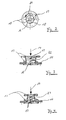
- a mixing drum 6 is flanged to a lantern 5, in the inner one Mixing room 7 a mixing tool 8 can be driven in rotation.
- the central axis 9 of the The mixing tool is aligned in the vertical direction.
- a vertical feed shaft At the top of the Mixing room 7 is a vertical feed shaft on this via a flange 10 11 screwed on. This feed shaft 11 has a smaller diameter than the mixing space 7 arranged below the feed shaft.
- Liquid supply connections 12 are provided on the flange 10, through which liquid (Arrows 13) can be fed into the mixing chamber 7 from above. Through a Guide tube, not shown, connected to the upper end of the feed shaft solids (arrow 14) coming from above likewise falls into the Feed shaft 11. This basic material is through a metering device, not shown abandoned in the desired amount.
- a propeller 15 rotates, in which on a shaft 16 several wings 17 are distributed over the circumference, as shown in FIG supervision can be recognized.
- the wings 17 project up to close the inner wall of the feed shaft 11, thus forming the propeller of a narrow gap.
- These wings 17 leave inside the feed shaft 11 several segments 18 free, which are axially parallel. at standing propeller 15 could directly through these segments 18 basic materials fall into the mixing room 7.
- the propeller 15 rotates at a speed of more than 200 revolutions per minute (see arrow 19). Characterized by the wing 17 in basic material already in the segments 18 within the feed shaft 11 homogenized before the liquid is then added to it in the mixing chamber 7, which is mixed with the base material by the mixing tool 8.
- the finished mixture is discharged from the mixing device through a discharge pipe 20 dissipated.
- a discharge pipe 20 dissipated.
- the mixing room 7 via cooling water connections 21 accordingly Temperature are maintained.
- the wings 17 are each arranged in one plane. It is also shown here Example to recognize that two levels, each with four wings arranged in it 17 are arranged one above the other, the corresponding wing 17 exactly lie on top of each other and as you can see it is easy to do. Through this Employment will promote the raw material homogenized by the propeller in the direction of the mixing room below the propeller.
- Feed shaft 22 agglomerates can be better disrupted.
- the invention thus represents a possibility of a mixing device to build with vertical orientation, where the feed chute is blocked is safely avoided and that due to a pre-homogenized Basic material also delivers very good mixing results.
Landscapes
- Chemical & Material Sciences (AREA)
- Chemical Kinetics & Catalysis (AREA)
- Dispersion Chemistry (AREA)
- Mixers Of The Rotary Stirring Type (AREA)
Applications Claiming Priority (2)
| Application Number | Priority Date | Filing Date | Title |
|---|---|---|---|
| DE10141302 | 2001-08-28 | ||
| DE10141302A DE10141302B4 (de) | 2001-08-28 | 2001-08-28 | Mischvorrichtung mit Propeller im Zuführschacht |
Publications (3)
| Publication Number | Publication Date |
|---|---|
| EP1287880A2 true EP1287880A2 (fr) | 2003-03-05 |
| EP1287880A3 EP1287880A3 (fr) | 2003-09-03 |
| EP1287880B1 EP1287880B1 (fr) | 2006-09-20 |
Family
ID=7696336
Family Applications (1)
| Application Number | Title | Priority Date | Filing Date |
|---|---|---|---|
| EP02018754A Expired - Lifetime EP1287880B1 (fr) | 2001-08-28 | 2002-08-22 | Appareil mélangeur |
Country Status (3)
| Country | Link |
|---|---|
| US (1) | US20030043691A1 (fr) |
| EP (1) | EP1287880B1 (fr) |
| DE (2) | DE10141302B4 (fr) |
Families Citing this family (1)
| Publication number | Priority date | Publication date | Assignee | Title |
|---|---|---|---|---|
| CN116651296B (zh) * | 2023-04-23 | 2023-12-15 | 江西大台农饲料有限公司 | 一种饲料生产用反应釜及生产方法 |
Family Cites Families (14)
| Publication number | Priority date | Publication date | Assignee | Title |
|---|---|---|---|---|
| US350524A (en) * | 1886-10-12 | Churn | ||
| US531718A (en) * | 1895-01-01 | And marshall g | ||
| US656674A (en) * | 1899-10-02 | 1900-08-28 | Albert H Stebbins | Ore-concentrating agitator. |
| US1432592A (en) * | 1921-08-03 | 1922-10-17 | Catini Federico | Attachment for soda-fountain faucets |
| US1859290A (en) * | 1929-10-09 | 1932-05-24 | Alemite Corp | Grease dispensing apparatus |
| US2074673A (en) * | 1933-08-10 | 1937-03-23 | Augustus J Sackett | Mixing machine |
| US3179380A (en) * | 1959-11-02 | 1965-04-20 | Dow Chemical Co | Apparatus for coagulation of colloidal dispersions |
| US3948491A (en) * | 1974-03-28 | 1976-04-06 | Perstorp Ab | Process for blending an additive such as colour pigment etc. with a plastic material and blending apparatus intended to be used for said process |
| US4190369A (en) * | 1976-10-13 | 1980-02-26 | National Engineering Company | Method and apparatus for making molds |
| DE7914349U1 (de) * | 1979-05-17 | 1980-10-23 | Wachter Kg Hindelang Baustoffwerk Bautechnik, 8973 Hindelang | Vorrichtung zum kontinuierlichen mischen eines trockengutes mit einer fluessigkeit und/oder einem schaumgut |
| US4611921A (en) * | 1984-12-24 | 1986-09-16 | Texaco Inc. | Debridging apparatus |
| SE503898C2 (sv) * | 1994-10-25 | 1996-09-30 | Tetra Laval Holdings & Finance | Blandare för blandning av vätskor eller suspensioner samt förfarande för blandning |
| DE19629945C5 (de) * | 1996-07-25 | 2008-10-16 | Ika-Werke Gmbh & Co. Kg | Mischvorrichtung zum Vermischen von pulverförmigen und/oder körnigen Partikeln mit einer Flüssigkeit |
| DE19714264A1 (de) * | 1997-04-07 | 1998-10-08 | Wacker Chemie Gmbh | Mobile Vorrichtung zur Herstellung von wäßrigen Flüssigfarben aus pulverförmigen Bestandteilen und Wasser |
-
2001
- 2001-08-28 DE DE10141302A patent/DE10141302B4/de not_active Expired - Fee Related
-
2002
- 2002-08-15 US US10/222,012 patent/US20030043691A1/en not_active Abandoned
- 2002-08-22 DE DE50208187T patent/DE50208187D1/de not_active Expired - Lifetime
- 2002-08-22 EP EP02018754A patent/EP1287880B1/fr not_active Expired - Lifetime
Also Published As
| Publication number | Publication date |
|---|---|
| DE10141302A1 (de) | 2003-03-27 |
| EP1287880A3 (fr) | 2003-09-03 |
| US20030043691A1 (en) | 2003-03-06 |
| DE10141302B4 (de) | 2004-03-25 |
| EP1287880B1 (fr) | 2006-09-20 |
| DE50208187D1 (de) | 2006-11-02 |
Similar Documents
| Publication | Publication Date | Title |
|---|---|---|
| AT413511B (de) | Vorrichtung zur aufbereitung von kunststoffmaterial zu recyclingzwecken | |
| DE2012645A1 (de) | Vorrichtung zum Extrudieren von schwer extrudierbaren Materialien, insbesondere von Kunststoffabfällen | |
| EP1628812B1 (fr) | Dispositif de traitement d'un materiau plastique en vue de son recyclage | |
| DE20011402U1 (de) | Vorrichtung zum Aufbereiten von thermoplastischem Kunststoffgut | |
| EP2155353A1 (fr) | Séparateur à vis à pression | |
| CH682788A5 (de) | Maschine zum Bearbeiten von Schokolademassen. | |
| EP3473395A1 (fr) | Arbre de vis sans fin à trois ailettes asymétrique pour machine de mélange et de pétrissage | |
| EP1155734B1 (fr) | Malaxeur vertical | |
| EP2092975A2 (fr) | Dispositif de mélange doté d'un pot de mélange fixé sur un récipient de mélange | |
| CH465840A (de) | Zufuhreinrichtung für eine Kunststoff-Schneckenpresse | |
| DE3342812A1 (de) | Vorrichtung und verfahren zur extrusion von zellulosehaltigen stoffen | |
| DE1082107B (de) | Vorrichtung zum Entnehmen von aufgeschlossenem Fasermaterial aus einem Druckgefaess | |
| DE2415593C2 (de) | Silo zum Speichern von schüttfähigem, jedoch schwerfließendem Gut | |
| DE10141302B4 (de) | Mischvorrichtung mit Propeller im Zuführschacht | |
| EP0587058A1 (fr) | Dispositif de remplissage notamment pour sacs à soupape | |
| EP3656523B1 (fr) | Mélangeur-malaxeur à ventilation efficace dans la zone d'alimentation, et procédé associé | |
| DE9408205U1 (de) | Anhänger zum Mischen, Zerkleinern und Verteilen von Tierfutter | |
| DE102017004281A1 (de) | Fördereinrichtung mit Förderschnecke und Klumpenbrecher | |
| DE19652323A1 (de) | Schneidsatz für eine Schneckenfördereinrichtung | |
| DE4241467A1 (de) | Vorrichtung zum Auftragen von Schüttgütern geringer Fließfähigkeit | |
| DE3304958C2 (de) | Vorrichtung zum Auflösen von Faserstoffen in Flüssigkeit | |
| EP0849393B1 (fr) | Décomposeur de déchets, en particulier à partir de déchets ménagers biologiques | |
| CH495900A (de) | Silo-Austragvorrichtung | |
| DE202024104986U1 (de) | Mischvorrichtung zur Vermischung von Futterkomponenten für ein Insektenfuttermittel, betreffende Futterküche und Verwendung | |
| DE1141517B (de) | Vorrichtung zum Zerkleinern, Mischen und Homogenisieren von Stoffen sowie zur Durchfuehrung mechano-chemischer Reaktionen |
Legal Events
| Date | Code | Title | Description |
|---|---|---|---|
| PUAI | Public reference made under article 153(3) epc to a published international application that has entered the european phase |
Free format text: ORIGINAL CODE: 0009012 |
|
| AK | Designated contracting states |
Designated state(s): AT BE BG CH CY CZ DE DK EE ES FI FR GB GR IE IT LI LU MC NL PT SE SK TR Kind code of ref document: A2 Designated state(s): AT BE BG CH CY CZ DE DK EE ES FI FR GB GR IE IT LI LU MC NL PT SE SK TR |
|
| AX | Request for extension of the european patent |
Extension state: AL LT LV MK RO SI |
|
| PUAL | Search report despatched |
Free format text: ORIGINAL CODE: 0009013 |
|
| AK | Designated contracting states |
Kind code of ref document: A3 Designated state(s): AT BE BG CH CY CZ DE DK EE ES FI FR GB GR IE IT LI LU MC NL PT SE SK TR |
|
| AX | Request for extension of the european patent |
Extension state: AL LT LV MK RO SI |
|
| RIC1 | Information provided on ipc code assigned before grant |
Ipc: 7B 01F 3/12 B Ipc: 7B 01F 7/20 A Ipc: 7B 01F 7/16 B Ipc: 7B 01F 13/10 B Ipc: 7B 01F 15/00 B Ipc: 7B 01F 7/18 B |
|
| 17P | Request for examination filed |
Effective date: 20030924 |
|
| AKX | Designation fees paid |
Designated state(s): CH DE GB LI |
|
| 17Q | First examination report despatched |
Effective date: 20040920 |
|
| GRAP | Despatch of communication of intention to grant a patent |
Free format text: ORIGINAL CODE: EPIDOSNIGR1 |
|
| GRAS | Grant fee paid |
Free format text: ORIGINAL CODE: EPIDOSNIGR3 |
|
| GRAA | (expected) grant |
Free format text: ORIGINAL CODE: 0009210 |
|
| AK | Designated contracting states |
Kind code of ref document: B1 Designated state(s): CH DE GB LI |
|
| REG | Reference to a national code |
Ref country code: GB Ref legal event code: FG4D Free format text: NOT ENGLISH |
|
| REG | Reference to a national code |
Ref country code: CH Ref legal event code: EP |
|
| REF | Corresponds to: |
Ref document number: 50208187 Country of ref document: DE Date of ref document: 20061102 Kind code of ref document: P |
|
| GBT | Gb: translation of ep patent filed (gb section 77(6)(a)/1977) |
Effective date: 20061122 |
|
| REG | Reference to a national code |
Ref country code: CH Ref legal event code: NV Representative=s name: R. A. EGLI & CO. PATENTANWAELTE |
|
| PLBE | No opposition filed within time limit |
Free format text: ORIGINAL CODE: 0009261 |
|
| STAA | Information on the status of an ep patent application or granted ep patent |
Free format text: STATUS: NO OPPOSITION FILED WITHIN TIME LIMIT |
|
| 26N | No opposition filed |
Effective date: 20070621 |
|
| PGFP | Annual fee paid to national office [announced via postgrant information from national office to epo] |
Ref country code: GB Payment date: 20080822 Year of fee payment: 7 |
|
| GBPC | Gb: european patent ceased through non-payment of renewal fee |
Effective date: 20090822 |
|
| PG25 | Lapsed in a contracting state [announced via postgrant information from national office to epo] |
Ref country code: GB Free format text: LAPSE BECAUSE OF NON-PAYMENT OF DUE FEES Effective date: 20090822 |
|
| PGFP | Annual fee paid to national office [announced via postgrant information from national office to epo] |
Ref country code: CH Payment date: 20110824 Year of fee payment: 10 |
|
| REG | Reference to a national code |
Ref country code: DE Ref legal event code: R082 Ref document number: 50208187 Country of ref document: DE Representative=s name: JANY UND PETERSEN PATENTANWAELTE PARTNERSCHAFT, DE Ref country code: DE Ref legal event code: R082 Ref document number: 50208187 Country of ref document: DE Representative=s name: PETERSEN, FRANK, DIPL.-ING., DE |
|
| PGFP | Annual fee paid to national office [announced via postgrant information from national office to epo] |
Ref country code: DE Payment date: 20121024 Year of fee payment: 11 |
|
| REG | Reference to a national code |
Ref country code: CH Ref legal event code: PL |
|
| PG25 | Lapsed in a contracting state [announced via postgrant information from national office to epo] |
Ref country code: DE Free format text: LAPSE BECAUSE OF NON-PAYMENT OF DUE FEES Effective date: 20140301 Ref country code: LI Free format text: LAPSE BECAUSE OF NON-PAYMENT OF DUE FEES Effective date: 20130831 Ref country code: CH Free format text: LAPSE BECAUSE OF NON-PAYMENT OF DUE FEES Effective date: 20130831 |
|
| REG | Reference to a national code |
Ref country code: DE Ref legal event code: R119 Ref document number: 50208187 Country of ref document: DE Effective date: 20140301 |
|
| REG | Reference to a national code |
Ref country code: DE Ref legal event code: R082 Ref document number: 50208187 Country of ref document: DE Representative=s name: PETERSEN, FRANK, DIPL.-ING., DE |