EP1287919A2 - Drückmaschine - Google Patents
Drückmaschine Download PDFInfo
- Publication number
- EP1287919A2 EP1287919A2 EP02011874A EP02011874A EP1287919A2 EP 1287919 A2 EP1287919 A2 EP 1287919A2 EP 02011874 A EP02011874 A EP 02011874A EP 02011874 A EP02011874 A EP 02011874A EP 1287919 A2 EP1287919 A2 EP 1287919A2
- Authority
- EP
- European Patent Office
- Prior art keywords
- guide
- support
- slide
- machine according
- sliding
- Prior art date
- Legal status (The legal status is an assumption and is not a legal conclusion. Google has not performed a legal analysis and makes no representation as to the accuracy of the status listed.)
- Granted
Links
Images



Classifications
-
- B—PERFORMING OPERATIONS; TRANSPORTING
- B23—MACHINE TOOLS; METAL-WORKING NOT OTHERWISE PROVIDED FOR
- B23Q—DETAILS, COMPONENTS, OR ACCESSORIES FOR MACHINE TOOLS, e.g. ARRANGEMENTS FOR COPYING OR CONTROLLING; MACHINE TOOLS IN GENERAL CHARACTERISED BY THE CONSTRUCTION OF PARTICULAR DETAILS OR COMPONENTS; COMBINATIONS OR ASSOCIATIONS OF METAL-WORKING MACHINES, NOT DIRECTED TO A PARTICULAR RESULT
- B23Q1/00—Members which are comprised in the general build-up of a form of machine, particularly relatively large fixed members
- B23Q1/25—Movable or adjustable work or tool supports
- B23Q1/44—Movable or adjustable work or tool supports using particular mechanisms
- B23Q1/56—Movable or adjustable work or tool supports using particular mechanisms with sliding pairs only, the sliding pairs being the first two elements of the mechanism
- B23Q1/58—Movable or adjustable work or tool supports using particular mechanisms with sliding pairs only, the sliding pairs being the first two elements of the mechanism a single sliding pair
-
- B—PERFORMING OPERATIONS; TRANSPORTING
- B21—MECHANICAL METAL-WORKING WITHOUT ESSENTIALLY REMOVING MATERIAL; PUNCHING METAL
- B21D—WORKING OR PROCESSING OF SHEET METAL OR METAL TUBES, RODS OR PROFILES WITHOUT ESSENTIALLY REMOVING MATERIAL; PUNCHING METAL
- B21D22/00—Shaping without cutting, by stamping, spinning, or deep-drawing
- B21D22/14—Spinning
-
- B—PERFORMING OPERATIONS; TRANSPORTING
- B23—MACHINE TOOLS; METAL-WORKING NOT OTHERWISE PROVIDED FOR
- B23Q—DETAILS, COMPONENTS, OR ACCESSORIES FOR MACHINE TOOLS, e.g. ARRANGEMENTS FOR COPYING OR CONTROLLING; MACHINE TOOLS IN GENERAL CHARACTERISED BY THE CONSTRUCTION OF PARTICULAR DETAILS OR COMPONENTS; COMBINATIONS OR ASSOCIATIONS OF METAL-WORKING MACHINES, NOT DIRECTED TO A PARTICULAR RESULT
- B23Q1/00—Members which are comprised in the general build-up of a form of machine, particularly relatively large fixed members
- B23Q1/25—Movable or adjustable work or tool supports
- B23Q1/26—Movable or adjustable work or tool supports characterised by constructional features relating to the co-operation of relatively movable members; Means for preventing relative movement of such members
- B23Q1/40—Movable or adjustable work or tool supports characterised by constructional features relating to the co-operation of relatively movable members; Means for preventing relative movement of such members using ball, roller or wheel arrangements
Definitions
- the invention relates to a spinning machine according to the preamble of claim 1.
- the forming tools for example pressure rollers, forming rollers and the like, and / or the workpiece to be machined on a movable one Hold support sled.
- the support sled is usually along one provided on the press machine Supporters can be moved longitudinally for pressing required relative movements between the forming tool and to be able to realize the workpiece.
- the object of the invention is a spinning machine to create with a precise machining at the same time comparatively short main and secondary times is possible.
- the spinning machine it becomes longitudinally displaceable Storage of the support sled along the Support carrier the simultaneous use of at least one Roller bearing rail guidance, for example a roller rail guidance, together with at least one sliding guide unit proposed.
- the unusual combination a roller bearing rail guide with a slide guide unit leads to the surprising result that the Support arrangement made of support carrier and movable on it stored support sled by this type of storage on the one hand has high rigidity and travel speeds of up to 13 m / min, while the Support arrangement on the other hand compared to the support arrangements known spinning machines very good Shows damping behavior.
- the invention Presses a precise work at enables short main and secondary times at the same time.
- the spinning machine become two sliding guide units for sliding storage of the support carriage used, the sliding guide units are biased against each other and the support sled in a defined position with regard to the roller bearing rail guide run smoothly.
- pre-tensioning the two sliding guide units against each other it is achieved that those acting on the support sled Vibrations even with large vibration amplitudes be effectively damped, since the preload force is at least one Most of those attacking the support sled while swinging Counteracts forces and balances them.
- the roller bearing rail guide is preferably for inclusion a first force component and one at right angles designed this extending second force component, wherein the two force components transverse to the direction of movement of the support sled are directed. That way ensures that the on the support sled in the main load directions attacking forces, for example vertically and horizontally attacking the support sled Forces absorbed by the roller bearing rail guide which makes the support slide very precise along the Support carrier can be performed.
- the sliding guide unit is in this embodiment with respect to the roller bearing rail guide preloadable, the from the sliding guide unit generated preload parallel to a of the two power components runs around the support sled support. It is particularly advantageous when the biasing force is parallel to the force component runs in the direction in which the greatest vibrations occur, in order to achieve the greatest possible damping effect.
- two roller bearing rail guides to be provided on both sides of the support slide are arranged on a common plane. This ensures that the support slide between the roller bearing rail guides is held to the support sled too with high forces acting on the support sled in one defined situation with respect to the support organization.
- the slide guide unit acts generated preload in a parallel to the common Level of the rolling bearing rail guides Biasing level.
- the spinning machine suggested two Provide sliding guide units on both sides of the Support slides are arranged.
- mutual Arrangement of the slide guide units becomes the support slide held between the slide guide units and led, causing a shift of the support slide in the plane in which the two sliding guide units are arranged are effectively prevented.
- the sliding guide unit the support slide or the support beam over the longest possible travel leads, the sliding guide unit or at least one the slide guide units on a guide bar, which in Direction of movement of the support slide runs on the the support sled or the support carrier is sliding.
- the sliding guide unit in their distance for the support sled and / or, if provided, also in their distance to a second sliding guide unit adjustable to design. This makes it possible to adjust the preload adjust and also vary, for example Compensate for wear.
- a sliding guide unit proposed a releasably attachable guide bar or a detachably attachable guide element for sliding guidance of the support sled or the support carrier having.
- the sliding guide unit has a fastening element and at least one between the guide bar or the guide element and the fastening element provided elastic element with which the Guide bar or the guide element on the fastener supported.
- the sliding guide unit is proposed to integrate into the roller bearing rail guide, whereby the space required for the sliding guide unit is reduced can be.
- a roller bearing guide is preferably a Rail guide used, which is a guide rail and has a leadership recording, which in turn on the Guide rail through at least one rolling element circulation unit is slidably mounted.
- the roller bearing rail guide designed in this way has the advantage of being one hand is able to absorb high forces while on the other hand allows high travel speeds at the same time.
- the spinning machine is further proposed the sliding guide unit in the To use the guide mount of the roller bearing rail guide, the sliding guide unit with its sliding surface on a the guide surfaces of the guide rail under tension sliding against the desired damping properties to effect.
- the support bracket is designed as a support housing, in which the support slide is slidably guided is.
- the support slide is slidably guided is.
- two Slideway units used on both sides of the Support slide arranged and fastened in the support housing are.
- the sliding guide units are against each other preloaded so that these with their sliding surfaces on Support slide slide under tension and the support sled in a defined position of the roller bearing rail guide.
- the Pressing machine with a roller bearing rail guide with a guide rail and one on this by a Rolling element revolving unit slidably mounted guide receptacle is used, proposed the guide rail on the support sled and the guide holder on the support bracket provided.
- roller bearing rail guide For lubricating the roller bearing rail guide and the sliding guide unit is particularly suggested at the To provide a common central lubrication, the roller bearing rail guide by hand or automatically and lubricate the sliding guide unit.
- the spinning machine is also the support carrier on one across the Support sled movable main sled attached to Allow movements of the support slide in one plane.
- the main slide can also be used here if necessary through a combination of a roller bearing rail guide and a sliding guide unit longitudinally displaceable on the frame of the Press machine can be stored.
- the support storage of the spinning machine according to the invention is also to be understood as an independent functional unit that with corresponding adaptation also in other machine tools as spinning machines, for example in spinning rolling machines, can be used.
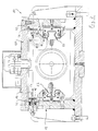
- the support arrangement 10 has a longitudinal section shown support housing 12 in which a support slide 14 is guided in a longitudinally displaceable manner. On that from the Support housing 12 protruding end of the support slide 14 are two pressure rollers 16 attached in a known manner, the used to form a workpiece, not shown become.
- the support slide 14 is with the help of a hydraulic cylinder 17 accommodated in the support slide 14 with respect to the support housing 12 in one direction of movement R can be moved in the longitudinal direction thereof around the pressure rollers 16 compared to the workpiece, not shown.
- the support housing 12 is in turn with a carriage 18 screwed, the cross to the direction of movement R of the support slide 14 can be moved along a carrier 20, which on the frame of the spinning machine, not shown is attached.
- Fig. 2 shows a sectional view transverse to the direction of movement R of the support slide 14.
- the support slide 14 is arranged by two on both sides of the support slide 14 Roller rail guides 22 out, which in The longitudinal direction of the support housing 12 run.
- each roller rail guide 22 has one Guide rail 24 on the one in question Side surface of the support slide 14 trained receiving groove 25 inserted and by screws on the support slide 14 is attached.
- each guide rail 24 26 displaceable by two roller circulation units 28 stored.
- the guide rail 24 has a watch glass-shaped Cross-sectional shape, making a total of four support surfaces 30 are formed, each with two support surfaces 30 at right angles one another to support each other Roll circulation unit 28 serve.
- everyone Roller rail guide 22 in four main loading directions Absorb forces so that a vertical force component F1 and at the same time a horizontal force component F2 of the roller rail guides 22 can be included.
- a receptacle 32 is provided on each side surface of the support slide 14, on the one of the two guide rails 24 in which the guide receptacle 26 as they move along the guide rail 24 emotional.
- Each guide receptacle 26 is on both sides of the Roller circulation units 28 arranged fastening screws 34 attached to the inside of the support housing 12.
- the respective guide seat 26 is supported a shoulder 36 formed in the support housing 12, while your back on one between the Support housing 12 and the rear plate arranged 38 is present under tension.
- a sliding guide unit 42 is arranged, the structure of which is explained in more detail below.
- each slide guide unit 42 a guide bar 44, which is in the direction of movement R of the support carriage 14 extends.
- the two Slideway units 42 are in a common plane arranged transversely to the direction of movement of the support slide 14 runs and parallel to the common plane is arranged in the two roller rail guides 22 are arranged.
- the slide guide units 42 are located each with their guide strips 44 opposite to each other Contact surfaces 46 on both sides of the support slide 14 on this one.
- the guide bar 44 is additional provided with a sliding surface 46 which over the entire length of the guide bar 44 extends and out a particularly slippery and wear-resistant material, for example bronze.
- 3 and 4 show, the guide strips 44th releasably attached to the support housing 12.
- 3 is one of the three fastening points through which each of the two slide guide units 42 on the support housing 12 is releasably attached, shown in section.
- To attach is in the guide bar 44 of the respective slide guide unit 42 screwed a retaining pin 50.
- On the Holding pin 50 is a plate spring assembly 52 pushed on.
- the holding pin 50 protrudes through a on the support housing 12 formed through thread 54.
- a clamping screw 56 screwed in with a concentric through hole 58 is provided.
- the holding pin 50 projects through the through bore 58, as a result of which this in a defined position with regard to the through thread 54 and thus with regard to the support housing 12 is held.
- the guide bar 44 is on the Contact surface 46 of the support carriage 40. simultaneously the guide bar 44, which is through the disc spring package 52 supported on the end face of the clamping screw 56, biased by the clamping screw 56 as soon as this is screwed into the through thread 54.
- 22 and the sliding guide units 42 have a common central lubrication provided with the help of lubricants to the Roller circulation units 28 and through the holding pin 50 to the guide strips 44 are supplied.
- Preload force Fv set on the guide bar 44 be so that the support carriage 14 under tension held between the two sliding guide units 42 is.
- the preload force Fv which is parallel to common level of the two roller rail guides 22 level, is set so that the support slide 14 from the guide rails 44 of the Slideway units 42 defined between the two Roller rail guides 22 is held.
- roller-rail guides 22 and the two sliding guide units 42 This combined arrangement of the roller-rail guides 22 and the two sliding guide units 42 is reached, that the forces acting on the support slide 14 that arise, for example, during forming, from the Roller circulation units 28 of the roller rail guides 22 be included.
- the sliding guide units 42 hold the support slide 14 in a defined position with respect to the roller rail guides 22, so that at Vibrations that attack the support slide 14, this Vibrations received by the slide guide units 42 and particularly effective due to the biasing force Fv can be damped without the vibrations from the roller rail guides 22 must be recorded and damped.
- the damping effect is additionally affected by the Lubricants or the lubricating films between the guide units 44 and the support slide 14 and by the Lubricants in the roller circulation units 28 increased.
- a The preload Fv can also be changed without change
- the lubrication can be done because the two sliding guide units 42 are independently adjustable.
- roller rail guides according to the invention 22 and the slide guide units 42 is thus a support arrangement 10 with very high rigidity at the same time realized very precise guidance accuracy, which is also compared to the known support arrangements due to excellent damping properties distinguished.
- this arrangement in particular achieved by the very good damping properties, that the support carriage 14 with almost double so high travel speed can be adjusted as in the previously known spinning machines. That's how they are Travel speeds of support slides in the state of the Technique at about 5 to 7 m / min while in the invention Pressing machine travel speeds of up to 13 m / min can be achieved.
- FIG. 5 to 7 is a second embodiment a support arrangement 10a shown, which also in the 1 arrangement alternative to the first embodiment can be used.
- the support arrangement 10a differs from that in the first exemplary embodiment previously described support arrangement 10 only in that the slide guide unit shown on the left in FIG. 5 42a integrated in the roller rail guide 22a is.
- the slide guide unit shown on the right in FIG. 5 42 and the roller rail guide arranged underneath 22 correspond to that previously with reference to FIG 2 to 4 explained first embodiment, so that on a detailed description of these components is subsequently waived.
- slide guide unit 42 is approximately cuboid Guide element 60 on its underside two parallel spaced-apart sliding inserts 42 are recorded, which are parallel to the longitudinal direction of the guide rail 24a of the roller rail guide 22a.
- a receiving pocket 64 which is symmetrical to Guide groove 65a of the guide receptacle 26a and centered between the end faces of the guide receptacle 26a is arranged.
- the receiving pocket 64a is dimensioned so that that the guide member 60 with a slight clearance fit can be inserted into the receiving pocket 64a.
- Im in the Guide receptacle 26a inserted state is the guide element 60 on the serving as a guide surface 66 Top of the guide rail 24a with its slide inserts 62a, as shown in FIG. 7, in which a cross section through the Roller rail guide 22a is shown.
- the guide element 60 also as in the first Embodiment, under tension on the guide rail 24a and thus abuts the support slide 14 the guide element 60 is also fastened in a prestressed manner.
- a retaining pin 68 screwed onto which a plate spring assembly 70 is postponed.
- the holding pin 68 protrudes also in this embodiment by a clamping screw 56a in a through thread 54a on the support housing 12a is screwed in.
- the through thread 54a is designed so that it is symmetrical to the guide rail 26a of the roller rail guide 22a and symmetrical is arranged for the guide receptacle 26a.
- the two support arrangements 10 and 10 described above 10a are used in the spinning machine according to the invention.
- the support arrangements 10 and 10a can, however can also be viewed as separate entities that are under also in spinning rolling machines or in conventional ones Machine tools can be used.
Landscapes
- Engineering & Computer Science (AREA)
- Mechanical Engineering (AREA)
- Spinning Or Twisting Of Yarns (AREA)
- Bearings For Parts Moving Linearly (AREA)
Abstract
Description
- Fig. 1
- eine Schnittansicht einer Supportanordnung einer Drückmaschine;
- Fig. 2
- eine Schnittansicht quer zur Bewegungsrichtung eines Supportschlittens der Supportanordnung eines ersten Ausführungsbeispiels einer erfindungsgemäßen Drückmaschine;
- Fig. 3
- eine vergrößerte Darstellung eines Details der Schnittansicht nach Fig. 3, in der eine Rollen-Schienenführung und eine Gleitführungseinheit der Supportanordnung dargestellt sind;
- Fig. 4
- einen vergrößerten Ausschnitt einer Draufsicht auf die Supportanordnung nach dem ersten Ausführungsbeispiel;
- Fig. 5
- eine Schnittansicht quer zur Bewegungsrichtung des Supportschlittens der Supportanordnung eines zweiten Ausführungsbeispiels einer erfindungsgemäßen Drückmaschine;
- Fig. 6
- eine perspektivische Darstellung einer Rollen-Schienenführung der Supportanordnung mit integrierter Gleitführungseinheit; und
- Fig. 7
- eine Schnittansicht der Rollen-Schienenführung nach Fig. 6 quer zur Längsrichtung der Führungsschiene.
Claims (14)
- Drückmaschine mit:dadurch gekennzeichnet, dass zum längsverschieblichen Lagern des Supportschlittens (14) entlang des Supportträgers (12) sowohl mindestens eine Wälzlager-Schienenführung (22) als auch mindestens eine Gleitführungseinheit (42) vorgesehen sind.einer drehbar antreibaren Spindel,mindestens einer Drückrolle (16),einem Supportträger (12) undeinem Supportschlitten (14), insbesondere zur Aufnahme der Drückrolle (16), der an dem Supportträger (12) längsverschieblich gelagert ist,
- Drückmaschine nach Anspruch 1,
dadurch gekennzeichnet,dass zwei Gleitführungseinheiten (42) vorgesehen sind, welche gegeneinander vorgespannt sind, unddass die gegeneinander vorgespannten Gleitführungseinheiten (42) den Supportschlitten (14) in einer definierten Lage bezüglich der Wälzlager-Schienenführung (22) gleitend führen. - Drückmaschine nach Anspruch 1 oder 2,
dadurch gekennzeichnet,dass die Wälzlager-Schienenführung (22) zur Aufnahme einer ersten Kraftkomponente (F1) und einer rechtwinklig zu dieser verlaufenden zweiten Kraftkomponente (F2) ausgelegt ist, welche quer zur Bewegungsrichtung (R) des Supportschlittens (14) gerichtet sind, unddass die Gleitführungseinheit (42) derart bezüglich der Wälzlager-Schienenführung (22) vorspannbar ist, dass die von der Gleitführungseinheit (42) erzeugte Vorspannkraft (Fv) parallel zu einer der beiden Kraftkomponenten (F1, F2) verläuft. - Drückmaschine nach Anspruch 3,
dadurch gekennzeichnet,dass zwei Wälzlager-Schienenführungen (22) vorgesehen und beiderseits des Supportschlittens (14) in einer gemeinsamen Ebene angeordnet sind unddass die Vorspannkraft (Fv) in einer parallel zur gemeinsamen Ebene der Wälzlager-Schienenführungen (22) verlaufenden Vorspannebene wirkt. - Drückmaschine nach einem der Ansprüche 1 bis 4,
dadurch gekennzeichnet,dass zwei Gleitführungseinheiten (42) vorgesehen und beiderseits des Supportschlittens (14) angeordnet sind unddass zumindest eine der Gleitführungseinheiten (42) unmittelbar zwischen dem Supportschlitten (14) und dem Supportträger (12) angeordnet ist. - Drückmaschine nach einem der Ansprüche 1 bis 5,
dadurch gekennzeichnet, dass zumindest eine der Gleitführungseinheiten (42) eine in Bewegungsrichtung (R) des Supportschlittens (14) verlaufende Führungsleiste (44) aufweist, mit der die Gleitführungseinheit (42) an dem Supportschlitten (14) oder an dem Supportträger (12) gleitend anliegt. - Drückmaschine nach einem der Ansprüche 1 bis 6,
dadurch gekennzeichnet, dass zumindest eine der Gleitführungseinheiten (42) zum Erzeugen einer Vorspannkraft (Fv) am Supportschlitten (14) in ihrem Abstand zu dem Schlitten (14) und/oder einer anderen Gleitführungseinheit (42) verstellbar ist. - Drückmaschine nach einem der Ansprüche 1 bis 7,
dadurch gekennzeichnet, dass die Gleitführungseinheit (42) eine Führungsleiste (44) oder ein Führungselement (60) zum gleitenden Führen des Supportschlittens (14) oder des Supportträgers (12), mindestens ein Befestigungselement (56) zum lösbaren Befestigen der Führungsleiste (44) oder des Führungselementes (60) am Supportträger (12) oder am Supportschlitten (14), sowie mindestens ein zwischen der Führungsleiste (44) oder dem Führungselement (60) und dem Befestigungselement (56) vorgesehenes elastisches Spannelement, insbesondere mindestens eine Tellerfeder (52) aufweist, mit dem sich die Führungsleiste (44) oder das Führungselement (60) am Befestigungselement (52) abstützt. - Drückmaschine nach einem der Ansprüche 1 bis 8,
dadurch gekennzeichnet, dass die Gleitführungseinheit (42) in der Wälzlager-Schienenführung (22) integriert ist. - Drückmaschine nach einem der Ansprüche 1 bis 9,
dadurch gekennzeichnet,dass jede Wälzlager-Schienenführung (22) eine Führungsschiene (24) und eine Führungsaufnahme (26) aufweist, welche an der Führungsschiene (24) durch mindestens eine Wälzkörper-Umlaufeinheit (28) verschieblich gelagert ist, unddass die Gleitführungseinheit (42) in die Führungsaufnahme (26) eingesetzt ist und mit ihrer Gleitfläche (62) an einer der Führungsflächen (66) der Führungsschiene (24) unter Vorspannung gleitend anliegt. - Drückmaschine nach einem der vorhergehenden Ansprüche,
dadurch gekennzeichnet,dass der Supportträger als Supportgehäuse (12) ausgeführt ist, in dem der Supportschlitten (14) verschieblich geführt ist,dass die Gleitführungseinheiten (42) beiderseits des Supportschlittens (14) angeordnet und im Supportgehäuse (12) befestigt sind, unddass die Gleitführungseinheiten (42) mit ihren Gleitflächen (48, 62) am Supportschlitten (14) unter Vorspannung gleitend anliegen. - Drückmaschine nach einem der vorhergehenden Ansprüche,
dadurch gekennzeichnet,dass jede Wälzlager-Schienenführung (22) eine Führungsschiene (24) und eine Führungsaufnahme (26) aufweist, welche an der Führungsschiene (24) durch mindestens eine Wälzkörper-Umlaufeinheit (28) verschieblich gelagert ist, unddass die Führungsschiene (24) am Supportschlitten (14) und die Führungsaufnahme (26) am Supportträger (12) vorgesehen ist. - Drückmaschine nach einem der vorhergehenden Ansprüche,
dadurch gekennzeichnet, dass eine gemeinsame Zentralschmierung für die mindestens eine Wälzlager-Schienenführung (22) und die mindestens eine Gleitführungseinheit (42) vorgesehen ist. - Drückmaschine nach einem der vorhergehenden Ansprüche,
dadurch gekennzeichnet, dass der Supportträger (12) seinerseits an einem quer zum Supportschlitten (14) verfahrbaren Hauptschlitten (18) befestigt ist.
Applications Claiming Priority (2)
| Application Number | Priority Date | Filing Date | Title |
|---|---|---|---|
| DE10138647 | 2001-08-07 | ||
| DE10138647A DE10138647A1 (de) | 2001-08-07 | 2001-08-07 | Drückmaschine |
Publications (3)
| Publication Number | Publication Date |
|---|---|
| EP1287919A2 true EP1287919A2 (de) | 2003-03-05 |
| EP1287919A3 EP1287919A3 (de) | 2003-07-30 |
| EP1287919B1 EP1287919B1 (de) | 2005-02-16 |
Family
ID=7694606
Family Applications (1)
| Application Number | Title | Priority Date | Filing Date |
|---|---|---|---|
| EP02011874A Expired - Lifetime EP1287919B1 (de) | 2001-08-07 | 2002-05-28 | Drückmaschine |
Country Status (3)
| Country | Link |
|---|---|
| EP (1) | EP1287919B1 (de) |
| DE (2) | DE10138647A1 (de) |
| ES (1) | ES2238520T3 (de) |
Family Cites Families (5)
| Publication number | Priority date | Publication date | Assignee | Title |
|---|---|---|---|---|
| JPS6368226A (ja) * | 1986-09-08 | 1988-03-28 | Nippon Spindle Mfg Co Ltd | スピニングマシンの駆動装置 |
| US4976126A (en) * | 1989-08-02 | 1990-12-11 | Kabushiki Kaisha Yamamoto Kinzoku Seisakusho | Spinning machine |
| DE4209824A1 (de) * | 1991-09-06 | 1993-03-11 | Schaeffler Waelzlager Kg | Waelzlager fuer linearbewegungen |
| SE469529B (sv) * | 1991-10-28 | 1993-07-19 | Leif Gullblom | Anordning foer sidostyrning av en loepare |
| JP2563104Y2 (ja) * | 1992-10-12 | 1998-02-18 | 日本精工株式会社 | 直動滑り案内軸受装置 |
-
2001
- 2001-08-07 DE DE10138647A patent/DE10138647A1/de not_active Withdrawn
-
2002
- 2002-05-28 ES ES02011874T patent/ES2238520T3/es not_active Expired - Lifetime
- 2002-05-28 EP EP02011874A patent/EP1287919B1/de not_active Expired - Lifetime
- 2002-05-28 DE DE50202265T patent/DE50202265D1/de not_active Expired - Fee Related
Also Published As
| Publication number | Publication date |
|---|---|
| DE50202265D1 (de) | 2005-03-24 |
| ES2238520T3 (es) | 2005-09-01 |
| DE10138647A1 (de) | 2002-04-04 |
| EP1287919B1 (de) | 2005-02-16 |
| EP1287919A3 (de) | 2003-07-30 |
Similar Documents
| Publication | Publication Date | Title |
|---|---|---|
| EP0391072B1 (de) | Wälzgelagerte Linearführungseinheit | |
| DE2728975C2 (de) | Plan- und Ausdrehkopf | |
| DE4032820C1 (de) | ||
| DE3429897C2 (de) | Einstellbare Geradführung für insbesondere Werkzeugmaschinen | |
| EP2478995B1 (de) | Vorrichtung mit einem verfahrbaren Schlitten und einer Linearführung | |
| DE4116795A1 (de) | Klemmvorrichtung fuer einen entlang einer oder mehrerer fuehrungsschienen bewegbaren tisch oder dergleichen | |
| DE4024686C2 (de) | Schienenführung mit umlaufenden Wälzlagern und Schwingungsdämpfungseinrichtung | |
| DE3131566C2 (de) | ||
| DE2346633A1 (de) | Fuehrung fuer relativ zueinander bewegbare maschinenteile | |
| CH672757A5 (de) | ||
| EP1466684B1 (de) | Maschine zur Bearbeitung von Werkstücken, insbesondere von Kurbel- und Nockenwellen, mit mindestens einem Innen-Rundfräswerkzeug | |
| DE2916280A1 (de) | Kombinierte waelz-/gleitfuehrung als geradfuehrung | |
| DE3015067C2 (de) | Druckmittel-entlastete Gleitführung | |
| EP2750827B1 (de) | Schlittenführung für einen maschinenschlitten einer werkzeugmaschine | |
| DE3925642A1 (de) | Werkzeugmaschine | |
| EP0171700A2 (de) | Einstellbare Wälzkörperumlauf-Geradführung | |
| EP1287919B1 (de) | Drückmaschine | |
| DE3917673C1 (de) | ||
| DE4402948C2 (de) | Spindelanordnung an einer Werkzeugmaschine | |
| EP1630434B1 (de) | Lineares Gleitführungssystem | |
| DE19648594A1 (de) | Hydrostatische Schlittenführung | |
| EP2318176B1 (de) | Werkzeugmaschine | |
| DE10116090C2 (de) | Laufbahn für eine Werkzeugmaschine | |
| DE4421004C2 (de) | Linearführungseinheit | |
| EP2823190A1 (de) | Schleifmaschine mit gleitführung |
Legal Events
| Date | Code | Title | Description |
|---|---|---|---|
| PUAI | Public reference made under article 153(3) epc to a published international application that has entered the european phase |
Free format text: ORIGINAL CODE: 0009012 |
|
| AK | Designated contracting states |
Designated state(s): AT BE CH CY DE DK ES FI FR GB GR IE IT LI LU MC NL PT SE TR Kind code of ref document: A2 Designated state(s): AT BE CH CY DE DK ES FI FR GB GR IE IT LI LU MC NL PT SE TR |
|
| AX | Request for extension of the european patent |
Extension state: AL LT LV MK RO SI |
|
| PUAL | Search report despatched |
Free format text: ORIGINAL CODE: 0009013 |
|
| AK | Designated contracting states |
Designated state(s): AT BE CH CY DE DK ES FI FR GB GR IE IT LI LU MC NL PT SE TR |
|
| AX | Request for extension of the european patent |
Extension state: AL LT LV MK RO SI |
|
| 17P | Request for examination filed |
Effective date: 20040115 |
|
| AKX | Designation fees paid |
Designated state(s): CH DE ES IT LI NL |
|
| GRAP | Despatch of communication of intention to grant a patent |
Free format text: ORIGINAL CODE: EPIDOSNIGR1 |
|
| GRAS | Grant fee paid |
Free format text: ORIGINAL CODE: EPIDOSNIGR3 |
|
| GRAA | (expected) grant |
Free format text: ORIGINAL CODE: 0009210 |
|
| AK | Designated contracting states |
Kind code of ref document: B1 Designated state(s): CH DE ES IT LI NL |
|
| REG | Reference to a national code |
Ref country code: CH Ref legal event code: EP |
|
| REG | Reference to a national code |
Ref country code: IE Ref legal event code: FG4D Free format text: GERMAN |
|
| REF | Corresponds to: |
Ref document number: 50202265 Country of ref document: DE Date of ref document: 20050324 Kind code of ref document: P |
|
| REG | Reference to a national code |
Ref country code: CH Ref legal event code: NV Representative=s name: SCHMAUDER & PARTNER AG PATENTANWALTSBUERO |
|
| REG | Reference to a national code |
Ref country code: ES Ref legal event code: FG2A Ref document number: 2238520 Country of ref document: ES Kind code of ref document: T3 |
|
| PLBE | No opposition filed within time limit |
Free format text: ORIGINAL CODE: 0009261 |
|
| STAA | Information on the status of an ep patent application or granted ep patent |
Free format text: STATUS: NO OPPOSITION FILED WITHIN TIME LIMIT |
|
| 26N | No opposition filed |
Effective date: 20051117 |
|
| PGFP | Annual fee paid to national office [announced via postgrant information from national office to epo] |
Ref country code: ES Payment date: 20090529 Year of fee payment: 8 Ref country code: NL Payment date: 20090527 Year of fee payment: 8 |
|
| REG | Reference to a national code |
Ref country code: CH Ref legal event code: PCAR Free format text: SCHMAUDER & PARTNER AG PATENT- UND MARKENANWAELTE VSP;ZWAENGIWEG 7;8038 ZUERICH (CH) |
|
| PGFP | Annual fee paid to national office [announced via postgrant information from national office to epo] |
Ref country code: DE Payment date: 20090527 Year of fee payment: 8 Ref country code: IT Payment date: 20090515 Year of fee payment: 8 |
|
| PGFP | Annual fee paid to national office [announced via postgrant information from national office to epo] |
Ref country code: CH Payment date: 20090529 Year of fee payment: 8 |
|
| REG | Reference to a national code |
Ref country code: NL Ref legal event code: V1 Effective date: 20101201 |
|
| REG | Reference to a national code |
Ref country code: CH Ref legal event code: PL |
|
| PG25 | Lapsed in a contracting state [announced via postgrant information from national office to epo] |
Ref country code: LI Free format text: LAPSE BECAUSE OF NON-PAYMENT OF DUE FEES Effective date: 20100531 Ref country code: CH Free format text: LAPSE BECAUSE OF NON-PAYMENT OF DUE FEES Effective date: 20100531 |
|
| PG25 | Lapsed in a contracting state [announced via postgrant information from national office to epo] |
Ref country code: IT Free format text: LAPSE BECAUSE OF NON-PAYMENT OF DUE FEES Effective date: 20100528 Ref country code: NL Free format text: LAPSE BECAUSE OF NON-PAYMENT OF DUE FEES Effective date: 20101201 |
|
| PG25 | Lapsed in a contracting state [announced via postgrant information from national office to epo] |
Ref country code: DE Free format text: LAPSE BECAUSE OF NON-PAYMENT OF DUE FEES Effective date: 20101201 |
|
| REG | Reference to a national code |
Ref country code: ES Ref legal event code: FD2A Effective date: 20110714 |
|
| PG25 | Lapsed in a contracting state [announced via postgrant information from national office to epo] |
Ref country code: ES Free format text: LAPSE BECAUSE OF NON-PAYMENT OF DUE FEES Effective date: 20110704 |
|
| PG25 | Lapsed in a contracting state [announced via postgrant information from national office to epo] |
Ref country code: ES Free format text: LAPSE BECAUSE OF NON-PAYMENT OF DUE FEES Effective date: 20100529 |