EP1287923B1 - Logement d' interrupteur dans un panneau frontal d' un appareil et sa méthode de production - Google Patents
Logement d' interrupteur dans un panneau frontal d' un appareil et sa méthode de production Download PDFInfo
- Publication number
- EP1287923B1 EP1287923B1 EP02019708A EP02019708A EP1287923B1 EP 1287923 B1 EP1287923 B1 EP 1287923B1 EP 02019708 A EP02019708 A EP 02019708A EP 02019708 A EP02019708 A EP 02019708A EP 1287923 B1 EP1287923 B1 EP 1287923B1
- Authority
- EP
- European Patent Office
- Prior art keywords
- impression
- switch
- cut
- metal plate
- rotary switch
- Prior art date
- Legal status (The legal status is an assumption and is not a legal conclusion. Google has not performed a legal analysis and makes no representation as to the accuracy of the status listed.)
- Expired - Lifetime
Links
- 238000000034 method Methods 0.000 title claims description 51
- 229910052751 metal Inorganic materials 0.000 claims abstract description 64
- 239000002184 metal Substances 0.000 claims abstract description 64
- 238000004519 manufacturing process Methods 0.000 claims abstract description 22
- 210000002105 tongue Anatomy 0.000 claims description 7
- 238000004080 punching Methods 0.000 claims description 6
- 235000020639 clam Nutrition 0.000 claims 10
- 241000237519 Bivalvia Species 0.000 claims 9
- 238000007373 indentation Methods 0.000 description 34
- 238000004049 embossing Methods 0.000 description 9
- 229910052782 aluminium Inorganic materials 0.000 description 6
- XAGFODPZIPBFFR-UHFFFAOYSA-N aluminium Chemical compound [Al] XAGFODPZIPBFFR-UHFFFAOYSA-N 0.000 description 6
- 229910001220 stainless steel Inorganic materials 0.000 description 5
- 239000010935 stainless steel Substances 0.000 description 5
- 239000000463 material Substances 0.000 description 4
- 238000013461 design Methods 0.000 description 3
- 238000005520 cutting process Methods 0.000 description 2
- 238000007598 dipping method Methods 0.000 description 2
- 210000003734 kidney Anatomy 0.000 description 2
- 238000003856 thermoforming Methods 0.000 description 2
- 230000000007 visual effect Effects 0.000 description 2
- XLYOFNOQVPJJNP-UHFFFAOYSA-N water Substances O XLYOFNOQVPJJNP-UHFFFAOYSA-N 0.000 description 2
- 229910000831 Steel Inorganic materials 0.000 description 1
- 206010047571 Visual impairment Diseases 0.000 description 1
- 230000015556 catabolic process Effects 0.000 description 1
- 238000010276 construction Methods 0.000 description 1
- 230000001419 dependent effect Effects 0.000 description 1
- 238000011161 development Methods 0.000 description 1
- 230000018109 developmental process Effects 0.000 description 1
- 230000000694 effects Effects 0.000 description 1
- 239000000835 fiber Substances 0.000 description 1
- 239000012530 fluid Substances 0.000 description 1
- 238000009434 installation Methods 0.000 description 1
- 238000003698 laser cutting Methods 0.000 description 1
- 238000001000 micrograph Methods 0.000 description 1
- 238000012986 modification Methods 0.000 description 1
- 230000004048 modification Effects 0.000 description 1
- 238000012545 processing Methods 0.000 description 1
- 239000010959 steel Substances 0.000 description 1
- 230000007704 transition Effects 0.000 description 1
- 208000029257 vision disease Diseases 0.000 description 1
- 230000004393 visual impairment Effects 0.000 description 1
Images

Classifications
-
- F—MECHANICAL ENGINEERING; LIGHTING; HEATING; WEAPONS; BLASTING
- F24—HEATING; RANGES; VENTILATING
- F24C—DOMESTIC STOVES OR RANGES ; DETAILS OF DOMESTIC STOVES OR RANGES, OF GENERAL APPLICATION
- F24C3/00—Stoves or ranges for gaseous fuels
- F24C3/12—Arrangement or mounting of control or safety devices
- F24C3/124—Control panels
-
- B—PERFORMING OPERATIONS; TRANSPORTING
- B21—MECHANICAL METAL-WORKING WITHOUT ESSENTIALLY REMOVING MATERIAL; PUNCHING METAL
- B21D—WORKING OR PROCESSING OF SHEET METAL OR METAL TUBES, RODS OR PROFILES WITHOUT ESSENTIALLY REMOVING MATERIAL; PUNCHING METAL
- B21D22/00—Shaping without cutting, by stamping, spinning, or deep-drawing
- B21D22/02—Stamping using rigid devices or tools
- B21D22/04—Stamping using rigid devices or tools for dimpling
Definitions
- the present invention relates to a device front according to the preambles of claims 18, 20, 21 and a method for producing the front of the device.
- immersive switch handles are often provided for aesthetic and functional reasons. In this case, impressions are provided for each switch receptacle in the front of the device, each of which is slightly larger in diameter than the cylindrical shift knob immersed therein by a few millimeters for a rotary switch. In this way, the impression of not placed on the front of the device, but in this immersed rotary switch.
- the manufacturing advantages of immersive switch handles are given, inter alia, that relatively inexpensive switch handles can be used, which must not be trimmed or otherwise reworked on their front edge facing the device, since this edge is covered by the embossed housing front.
- a conventional switch assembly in an electric cooker is known from DE-PS 810 183, in which only one passage for the rotary axis is provided by the switch front for the round rotary switch.
- the rotary handles which have a much larger diameter than their axis of rotation, are placed on the smooth-surface housing front with which the above-mentioned disadvantages in terms of manufacturing expense in the processing of the rotary handles are connected.
- a similar switch arrangement is also known from DE 43 31 551 A1.
- a method for producing a switch front made of plastic with deep-drawn switch receptacles is known from DE 38 40 542 C1.
- the plastic is formed isostatically by means of a pressurized fluid, with a colored printing of the plastic surface remains largely distortion-free.
- embossments for receiving immersive switch handles in front panels made of metal sheet such as aluminum, stainless steel or the like. Introduced, there is a risk that in the necessary thermoforming process, a slight distortion of the visible environment of the switch knob in the front of the device arises. If the front of the device is polished or provided with a microsection, this distortion can lead to visible disturbing effects in the metal surface or in the microsection.
- Another way to represent immersive switch handles is to provide a circular implementation in the switch front, through which the rotary handle is inserted.
- the implementation has a minimally larger diameter than the rotary handle.
- a separate receptacle or attachment is provided for each switch, for example, a sheet metal passage with rear end comes into question.
- this design has the disadvantage of additional construction costs for the switch mounting on an additional sheet, which is connected to the back of the device front.
- the present invention is therefore based on the object to avoid the disadvantages of the prior art and to provide a device front with a switch receptacle and a method for manufacturing a device front, in which the installation of immersed switch handles is possible without causing distortions in the front of the device become visible.
- a front panel for a rotary switch by impressing a circular indentation in a metal sheet for receiving a rotary switch, first a central passage for receiving a rotation axis of the rotary switch and then at least four recesses or openings are introduced into the metal sheet, which extend from an inner edge of the intended imprint. Subsequently, the impression is introduced.
- any distortion of the visible front area about the rotary switch is virtually eliminated, since during deep drawing of the front panel substantially the portion within the indentation between the recesses or openings is subject to a targeted stretching, but not the area around the indentation.
- the recesses may, for example, each have a kidney-shaped contour and follow the annular course of the imprint.
- the webs, which divide the recesses are stretched during deep drawing.
- a front panel with recording for a rotary switch by impressing a circular indentation in a metal sheet for receiving a rotary switch initially a central implementation for receiving a rotation axis of the rotary switch and possibly mounting holes for mounting the switch in a metal sheet of a front panel brought in.
- the central breakthrough has a much smaller diameter than the intended impression.
- a number of radial and / or oblique-radial openings are introduced into the metal sheet, which extend from a ring around the central aperture to close to the outer radius of the subsequently introduced indentation.
- the impression arranged concentrically to the aperture is introduced into the metal sheet of the front of the device.
- the metal sheet is specifically weakened in the region of the embossment by means of the apertures, so that essentially only the webs between the apertures are stretched in the subsequent embossing process, but not the material outside the embossing.
- the metal sheet which remains visible even after the switch assembly, no distortion. This is particularly advantageous in Gepatiusefronten from sanding steel or aluminum sheet, in which a material distortion would lead to disturbing visual effects in the microsection near the rotary switches.
- Another alternative method for producing a switch receptacle in the form of a circular impression in a metal sheet provides that before or after the production of mounting holes for attaching a switch, a fourth Recess with smaller dimensions than the intended imprint is introduced into the metal sheet, which has a central region and therefrom outgoing recesses in the form of lobe sections, which are separated by sheet metal tongues, and that subsequently the imprint is introduced into the metal sheet.
- the metal tongues In the deep-drawing process for producing the impression, the metal tongues essentially retain their shape. It is only widened the central area in the middle of the imprint through which the switch axis of rotation extends. The front panel around the imprint remains free of any distortion and therefore remains visually intact.
- Another alternative method for producing a switch receptacle in the form of a circular impression in a metal sheet provides that before or after the production of mounting holes for fastening a switch, a fifth recess with smaller dimensions than the intended impression is introduced into the metal sheet, which has a central Having area and adjoining recesses in the form of circular ring segments, and that subsequently the impression is introduced into the metal sheet.
- a fifth recess with smaller dimensions than the intended impression is introduced into the metal sheet, which has a central Having area and adjoining recesses in the form of circular ring segments, and that subsequently the impression is introduced into the metal sheet.
- at least two third recesses are provided, whose outer boundary follows approximately the course of an inner edge of the imprint.
- the indentation is introduced by means of a deep-drawing process, which has the advantage of a quick and easy producible indentation for the realization of immersed switch handles.
- the deep-drawing process is particularly suitable for mass production of large batches of device front sheets.
- a metal stamp is pressed in a gentle manner under high pressure in the metal sheet, wherein the desired impression is formed in the metal surface.
- a further embodiment according to the invention provides that the indentation has a depth of up to 10% of its outer diameter.
- the indentation may, for example, have a preferred depth of about 3 mm. This depth of 3mm is sufficient to create the visual impression of a switch "dipping" into the front of the device.
- the embossing in this form according to the invention causes no effective train on the visible surface of the switch front when it is produced in the deep-drawing tool.
- an impression of up to 3 - 4 mm deep can be produced without lateral "stretching" of the metal sheet, whereby a distortion of e.g. excluded from micrographs on stainless steel or aluminum.
- the indentation has a flat base and a rounded edge between the device front plate and circumferential embossing.
- This rounded edge can be realized by a correspondingly shaped plunger of the thermoforming tool and has the advantage of a lower material stress compared to a sharp edge.
- the edge between the cylindrical inner circumferential surface and the bottom of the indentation can also be rounded, as a result of which a soft deflection in the fiber path of the metal sheet and thus a lower material load result.
- the radial or oblique-radial openings can be produced in a simple manner by means of a punching process.
- a punching process is particularly suitable for mass production with high quantities.
- other methods for introducing the holes and openings are possible, for example. Laser cutting or water jet cutting or the like.
- larger apertures are respectively made around the fastening holes, which are arranged on a larger diameter than the central opening for the switch axis, which each extend around the fastening holes along the outer diameter of the embossing.
- These L-shaped apertures thus also go out from the ring surrounding the central aperture, but each extend around a mounting hole and extend along the outer circumference of the indentation, whereby Overall, an L-shaped contour is formed in the inner angle, the mounting hole is located.
- This special contour has the advantage of extensive strain relief of the mounting holes in the deep drawing process, whereby a longitudinal distortion of the holes is almost excluded.
- This has the advantage that the predetermined by the central implementation of the switch axis and through the mounting holes exact mounting position of the rotary switch can not be moved by a possible delay of the mounting holes. By relieving the mounting holes they always remain in their exact intended position.
- the webs between the elongated apertures between 1 and 3 mm wide, so that they can be subject during the deep drawing process of controlled elongation.
- a typical switch diameter of about 40 mm and thus slightly larger diameter of the indentation can be provided, for example, 14 radial or oblique-radial openings, which at a diameter of the central breakthrough surrounding ring of about 20 mm each have a length of about 8 to 9 mm and a width of about 2 mm inside to 4 mm outside.
- the interposed webs with a width of about 1.5 mm ensure that in the deep drawing process for producing the impression substantially only the webs themselves are subject to a stretching process, but not the inner ring around the central opening or the area of the metal sheet in the immediate environment of the imprint.
- the device fronts which are produced by the inventive method, are particularly suitable for the realization of so-called.
- Submerged rotary switches whose lower edges are covered by the front of the housing.
- the front panel of sheet metal with the switch receptacles can be provided with a grinding pattern that is not warped or otherwise affected by the production of the necessary for the switch shots indentations. Even a polished or brushed front made of aluminum or stainless steel sheet is subject by the switch mounts no visible delay.
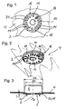
- Figure 1 shows a section of a front panel, which is prepared for mounting a plurality of rotary switch.
- the front of the device consists of a thin metal sheet 4, which may be made of brushed or sanded aluminum or stainless steel, for example.
- a central feedthrough 10 for an axis of rotation of a rotary switch is surrounded by an inner annular section 18, to which a number of radially elongated or obliquely radially aligned elongated openings adjoin outwards.
- two oppositely disposed mounting holes 12 are provided, which can serve for screwing the rotary switch.
- these mounting holes 12 are only optional and not essential for screwing the rotary switch. This can also be fixed by a central screw on the central passage 10.
- the envelope of the inner half-circle portions of the apertures 14, 16 forms the outer edge of the inner ring portion 18, which is arranged concentrically around the central passage 10.
- the envelope of the outer half-circle sections of the elongated openings 14 has a slightly smaller diameter than the embossment 2 more clearly visible in FIGS. 2 and 3.
- there are two L-shaped openings 16 is provided, in each of whose angles one of the two mounting holes is arranged.
- a longer portion of each L-shaped aperture 16 extends along the inner edge 22 of the indentation 2 (see also Figure 2).
- the L-shaped Breakthroughs 16 each bend in a shorter section, which also extends obliquely-radially as the other openings 14, so that the inner semicircular portion adjacent to the inner ring portion 18.
- a first web 24 is provided in each case; these webs take up substantially all of the elongation during the deep-drawing process for producing the embossment 2.
- the particular contour of the L-shaped apertures 16 results from the necessity that the contours and geometry of the inner ring portion 18, the mounting holes 12 and the central feedthrough 10 should remain as unchanged as possible in the deep drawing process for producing the impression 2 to the unique Positioning and proper mounting of the rotary switch to be able to guarantee.
- the openings 14, 16, the central passage 10 and the optional mounting holes 12 can be advantageously introduced by means of a punching process in the metal sheet 4.
- This method has the advantage of a relatively low production costs and resulting low production costs.
- a large number of front panels can be processed in this way in rapid succession. Equally possible, however, is the production of the holes and openings by means of laser and / or water jet cutting. It is only essential that the openings 14 16 are introduced before the metal sheet 4 is embossed by deep drawing.
- An electric cooker or other household appliance are typically several such side by side and / or superposed rotary switches, which are referred to as "dipping" switch handles.
- FIG. 2 shows a perspective cutout on the metal sheet 4 of an appliance front provided with an impression 2.
- the same parts as in Figure 1 are provided with the same reference numerals and are therefore not explained several times.
- the inner edge 22 of the indentation 2 is adjacent to the envelope of the outer semicircular portions of the apertures 14.
- the longer portion of the L-shaped apertures 16 each directly adjoin the inner and outer edges 20, 22 of the indentation 2.
- a typical rotary knob of a rotary switch 8 for a household electrical appliance such as a cooker or the like may, for example, have a diameter D1 of about 40 mm.
- the inner diameter D2 of the embossing must be slightly larger in order to accommodate the knob of the rotary switch 8 without contact.
- the depth T of the indentation 2 can have up to 10% of its diameter D2, in the present case thus up to 4 mm, without a distortion of the metal sheet 4 is to be expected.
- a depth T of the indentation 2 of less than 4 mm with a typical sheet thickness of about 1 mm can thus reliably exclude a visual impairment of a brushed or ground device front made of stainless steel or aluminum sheet due to distortion during deep drawing.
- the inner ring portion 18, which adjoins the envelope of the inner half-circle sections of the radial and / or oblique-radial openings 14, have an outer diameter of about 20 mm.
- the centers of the two opposite mounting holes are about 28 mm apart; the mounting holes themselves may have a diameter of, for example, 3 to 4 mm.
- a total of about 14 radial or oblique-radial openings 14, 16 may be provided, each having a length of about 8 to 10 mm and a width of 2 mm inside to 4 mm outside.
- the interposed first webs 24 with a width of about 1.5 mm ensure that in the deep drawing process for producing the impression 2 essentially only the first webs 24 themselves are subject to a stretching process, but not the inner ring portion 18 to the central implementation 10 or the area of the metal sheet 4 in the immediate external environment of the imprint.
- FIGS. 4 to 6 show further alternative designs of switch receptacles in a front of the device.
- the same parts as in the previously described Figures 1 to 3 are basically provided with the same reference numerals and will therefore not be explained several times.
- the switch receptacle illustrated in FIG. 4 like the switch receptacle shown in FIGS. 1 and 2, has a central feedthrough 10 for a rotation axis 6 of a rotary switch 8 (see FIG.
- This central passage 10 is also surrounded by an inner ring portion 18, to which, however, only four recesses 26, 28 connect to the outside.
- Also outside of the inner ring portion 18 two oppositely disposed mounting holes 12 are provided, which can serve for screwing the rotary switch 6.
- These mounting holes 12 are optional and not essential for screwing the rotary switch 6. This can also be fixed by a central screw on the central passage 10.
- each first recesses 26 Symmetrical to an axis through the center of the central passage 10 and rotated by 90 ° to an axis which simultaneously passes through the mounting holes 12, two oppositely disposed first recesses 26 are provided, each having a kidney-shaped contour.
- An inner edge of each first recess 26 forms an outer boundary of the inner ring portion 18 made of sheet metal and follows a circular line which is concentric with the central passage 10 and the impression 2.
- An outer edge of each first recess 26 extends along the indentation 2 and a minimally smaller radius than this.
- a semicircle connects tangentially, which closes the kidney shape of the first recesses 26.
- each have a sheet metal portion is provided, which constricts each of the inner edges of two oppositely disposed second recesses 28, so that these inner edges describe a much smaller radius as the inner edges of the first recesses 26.
- the kidney-shaped first recesses 26 and the second recesses 28 each describe a circular segment with an opening angle of about 35 to 40 °.
- the first and second recesses 26, 28 alternating over the circumference of the indentation 2 are each separated by second webs 29 made of metal, which in the deep-drawing process for introducing the indentation 2 are subjected to the strongest deformation overall.
- the inner ring portion 18 together with the sheet metal sections to the mounting holes 12 is subject during deep drawing almost no deformation Due to the possibility of stretching the relatively thin second webs 29 any deformation of the embossing 2 surrounding metal sheet 4 can be largely avoided.
- FIGS. 5 and 6 do not have a closed, circular central leadthrough for the central fastening of a rotary switch 8.
- the passage for the axis of rotation 6 of a rotary switch 8 is here in each case formed by a central region 38 with a larger diameter than the central feedthrough 10 (corresponding to FIGS. 1 to 4).
- the two mutually opposite mounting holes 12 for screwing or otherwise securing the rotary switch 8 are necessary in these embodiments, in contrast to the embodiments described above.
- Figure 5 shows a switch receptacle with a circular indentation 2 and a fourth recess 32.
- This fourth recess 32 is formed by six inwardly to the central region 38 facing sheet metal tongues 42, which are each separated by recesses in the form of lobe sections 34.
- the mounting holes 12 are provided.
- the remaining four sheet tabs 42 without mounting holes 12 can be made slightly narrower.
- the outer edges of the lobe portions 34 are provided with a semicircular contour and are adjacent to the annular inner edge 22 formed by the indentation 2.
- the inwardly facing inner edges of the latches 42 each describe circular segments of the circular central one Area 38, so that in each case at the transitions from the central region 38 to the lobe sections 34 edges are formed with a relatively small radius of curvature.
- the indentation 2 can be introduced by means of a deep-drawing process without the risk of deformation of the metal sheet 4 surrounding the indentation 2.
- the sheet metal tongues 42 are subject to only minimal elongation.
- FIG. 6 shows a fourth embodiment of a switch receptacle according to the invention with a circular indentation 2 and with a fifth recess 36.
- the two circular ring segments 40 each terminate with a radius close to the inner edge 22.
- the outer boundary of each circular segment 40 intersects with the central region 38, so that a total of a contour of the fifth recess 36 is formed, which removes a so-called Grenzrachenlehre with bulbous Middle section remembers.
- each third recesses 30 are provided, each having a kidney-shaped contour.
- An inner edge of each third recess 30 is separated from the central portion 38 by an inner support segment 19, which is a relatively wide sheet metal section. The inner edge follows a circular line which is concentric with the inner edge 22 of the indentation 2.
- An outer edge of each third recess 30 extends along the inner edge 22 of the indentation 2 or on only a minimally smaller radius than this.
- a semicircle connects tangentially, which closes the kidney shape of the third recesses 30.
- the indentation 2 can be introduced by means of a deep-drawing process without the risk of a deformation of the metal sheet 4 surrounding the indentation 2.
- the inner support segments 19 are subject to only minimal elongation.
Landscapes
- Engineering & Computer Science (AREA)
- Mechanical Engineering (AREA)
- Chemical & Material Sciences (AREA)
- Combustion & Propulsion (AREA)
- General Engineering & Computer Science (AREA)
- Rotary Switch, Piano Key Switch, And Lever Switch (AREA)
- Shaping Metal By Deep-Drawing, Or The Like (AREA)
- Manufacture Of Switches (AREA)
- Supplying Of Containers To The Packaging Station (AREA)
- Coupling Device And Connection With Printed Circuit (AREA)
- Push-Button Switches (AREA)
Claims (24)
- Procédé de fabrication d'un panneau frontal d'appareil avec logement pour un commutateur rotatif par estampage d'une empreinte circulaire (2) dans une tôle métallique (4) pour le logement d'un commutateur rotatif (8), dans lequel, avant ou après la fabrication d'un passage central (10) de diamètre plus petit que l'empreinte prévue (2), au moins quatre évidements (26, 28, 30) resp. ouvertures (14, 16) sont appliqués dans la tôle métallique (4) pour le logement d'un axe de rotation (6) du commutateur rotatif (8) et éventuellement avant ou après la fabrication de trous de fixation (12) pour la fixation du commutateur (8), ces évidements resp. ouvertures s'étendant d'une section annulaire intérieure (18) autour du passage central (10) jusqu'à proximité du bord extérieur de l'empreinte prévue (2), et dans lequel l'empreinte (2) est ensuite appliquée dans la tôle métallique (4).
- Procédé selon la revendication 1, caractérisé en ce que les évidements (26, 28, 30) présentent chacun un contour réniforme, un bord extérieur de chaque évidement (26, 28) passant le long de l'empreinte (2).
- Procédé selon la revendication 1 ou 2, caractérisé en ce qu'un bord intérieur de chacun des au moins deux premiers évidements (26) est adjacent à la section annulaire intérieure (18) et en ce qu'un bord intérieur de chacun des au moins deux deuxièmes évidements (28) décrit un demi-cercle autour des trous de fixation (12).
- Procédé selon la revendication 1, caractérisé en ce qu'un nombre d'ouvertures radiales et/ou radialement inclinées (14, 16) sont appliquées dans la tôle métallique (4), celles-ci s'étendant d'une section annulaire intérieure (18) autour du passage central (10) jusqu'à proximité du bord extérieur de l'empreinte prévue (2).
- Procédé de fabrication d'un panneau frontal d'appareil avec logement pour un commutateur rotatif par estampage d'une empreinte circulaire (2) dans une tôle métallique (4) pour le logement d'un commutateur rotatif (8), dans lequel, avant ou après la fabrication de trous de fixation (12) pour la fixation du commutateur (8), un quatrième évidement (32) aux dimensions plus petites que l'empreinte prévue (2) est appliqué pour le logement d'un axe de rotation (6) du commutateur rotatif (8) dans la tôle métallique (4), cet évidement présentant une partie centrale (38) ainsi que des évidements, qui en partent, sous forme de sections en massue (34) séparées par des languettes en tôle (42), et dans lequel l'empreinte (2) est ensuite appliquée dans la tôle métallique (4).
- Procédé de fabrication d'un panneau frontal d'appareil avec logement pour un commutateur rotatif par estampage d'une empreinte circulaire (2) dans une tôle métallique (4) pour le logement d'un commutateur rotatif (8), dans lequel, avant ou après la fabrication de trous de fixation (12) pour la fixation du commutateur (8), un cinquième évidement (36) aux dimensions plus petites que l'empreinte prévue (2) est appliqué pour le logement d'un axe de rotation (6) du commutateur rotatif (8) dans la tôle métallique (4), cet évidement présentant une partie centrale (38) ainsi que des évidements, qui s'y raccordent, sous forme de segments en anneaux circulaires (40), et dans lequel l'empreinte (2) est ensuite appliquée dans la tôle métallique (4).
- Procédé selon la revendication 6, caractérisé en ce qu'en plus du cinquième évidement (36) au moins deux troisièmes évidements (30) en forme de massue sont appliqués, dont la limite extérieure suit respectivement à peu près l'allure d'un bord intérieur (22) de l'empreinte (2).
- Procédé selon l'une quelconque des revendications précédentes, caractérisé en ce que l'empreinte (2) est appliquée au moyen d'un procédé d'emboutissage.
- Procédé selon l'une quelconque des revendications précédentes, caractérisé en ce que l'empreinte (2) présente une profondeur (T) allant jusqu'à 3 mm.
- Procédé selon l'une quelconque des revendications 1 à 8, caractérisé en ce que l'empreinte (2) présente une profondeur (T) allant jusqu'à 10% de son diamètre extérieur (D2).
- Procédé selon l'une quelconque des revendications précédentes, caractérisé en ce que l'empreinte (2) présente un fond plat ainsi qu'un bord arrondi (20) entre la tôle métallique (4) et l'empreinte périphérique (2).
- Procédé selon l'une quelconque des revendications 1 à 4 ou 8 à 11, caractérisé en ce que le passage central (10) et les trous de fixation (12) sont appliqués au moyen d'une opération de découpage.
- Procédé selon l'une quelconque des revendications 5 à 11, caractérisé en ce que le quatrième resp. le cinquième évidement (32 resp. 36) et les trous de fixation (12) sont appliqués au moyen d'une opération de découpage.
- Procédé selon l'une quelconque des revendications précédentes, caractérisé en ce que les ouvertures (14, 16) resp. les évidements (26, 28, 30) sont appliqués au moyen d'une opération de découpage.
- Procédé selon l'une quelconque des revendications 1 à 4 ou 8 à 14, caractérisé en ce que des ouvertures respectivement plus grandes (16) sont appliquées autour des trous de fixation (12), celles-ci s'étendant respectivement autour des trous de fixation (12) le long du diamètre extérieur (D2) de l'empreinte (2).
- Procédé selon la revendication 15, caractérisé en ce que les premières nervures (24) entre les ouvertures (14, 16) ont respectivement une largeur comprise entre 1 et 3 mm.
- Procédé selon l'une quelconque des revendications précédentes, caractérisé en ce que lors de l'opération d'emboutissage, essentiellement seulement les premières resp. les deuxièmes nervures (24 resp. 29) entre les ouvertures (14, 16) resp. entre la section annulaire intérieure (18) et le bord intérieur (22) sont soumises à une opération d'étirement.
- Panneau frontal d'appareil comprenant un logement de commutateur pour le logement d'un commutateur rotatif rond (8) qui peut être installé en partie en étant enfoncé dans le panneau frontal d'appareil en tôle métallique (4), une empreinte (2) de diamètre plus grand (D2) que le commutateur rotatif prévu (8) étant prévue dans le panneau frontal d'appareil, caractérisé en ce qu'à l'intérieur de l'empreinte (2), au moins quatre ouvertures (14, 16, 26, 28, 30) sont appliquées dans la tôle métallique (4), qui s'étendent d'une section annulaire intérieure (18) autour d'un passage central (10) pour l'axe de rotation (6) du commutateur, jusqu'à proximité du bord extérieur de l'empreinte (2).
- Panneau frontal d'appareil selon la revendication 18, caractérisé en ce qu'à l'intérieur de l'empreinte (2), un nombre d'ouvertures radiales et/ou radialement inclinées (14, 16) sont appliquées dans la tôle métallique (4), celles-ci s'étendant d'une section annulaire intérieure (18) autour d'un passage central (10) pour l'axe de rotation (6) du commutateur, jusqu'à proximité du bord extérieur de l'empreinte (2).
- Panneau frontal d'appareil comprenant un logement de commutateur pour le logement d'un commutateur rotatif rond (8) qui peut être installé en partie en étant enfoncé dans le panneau frontal d'appareil en tôle métallique (4), une empreinte (2) de diamètre plus grand (D2) que le commutateur rotatif prévu (8) étant prévue dans le panneau frontal d'appareil, caractérisé en ce qu'à l'intérieur de l'empreinte (2), un quatrième évidement (32) aux dimensions plus petites que l'empreinte prévue (2) est appliqué dans la tôle métallique (4) pour le logement d'un axe de rotation (6) du commutateur rotatif (8), cet évidement présentant une partie centrale (38) ainsi que des évidements qui en partent sous la forme de sections en forme de massue (34) séparées par des languettes en tôle (42).
- Panneau frontal d'appareil comprenant un logement de commutateur pour le logement d'un commutateur rotatif rond (8) qui peut être installé en partie en étant enfoncé dans le panneau frontal d'appareil en tôle métallique (4), une empreinte (2) de diamètre plus grand (D2) que le commutateur rotatif prévu (8) étant prévue dans le panneau frontal d'appareil, caractérisé en ce qu'à l'intérieur de l'empreinte (2), un cinquième évidement (36) aux dimensions plus petites que l'empreinte prévue (2) est appliqué dans la tôle métallique (4) pour le logement d'un axe de rotation (6) du commutateur rotatif (8), cet évidement présentant une partie centrale (38) ainsi que des évidements qui s'y raccordent sous forme de segments en anneaux circulaires (40).
- Panneau frontal d'appareil selon la revendication 21, caractérisé en ce qu'en plus du cinquième évidement (36), au moins deux troisièmes évidements (30) en forme de massue sont appliqués, dont la limite extérieure suit respectivement à peu près l'allure d'un bord intérieur (22) de l'empreinte (2).
- Panneau frontal d'appareil selon l'une quelconque des revendications 18 à 22, caractérisé en ce que l'empreinte (2) présente une profondeur (T) allant jusqu'à 10% de son diamètre extérieur (D2).
- Panneau frontal d'appareil selon l'une quelconque des revendications 18 à 23, caractérisé en ce que l'empreinte (2) présente respectivement des bords arrondis (20, 22).
Applications Claiming Priority (2)
| Application Number | Priority Date | Filing Date | Title |
|---|---|---|---|
| DE10143049A DE10143049A1 (de) | 2001-09-03 | 2001-09-03 | Schalteraufnahme in einer Gerätefront und Verfahren zur Herstellung der Schalteraufnahme |
| DE10143049 | 2001-09-03 |
Publications (3)
| Publication Number | Publication Date |
|---|---|
| EP1287923A2 EP1287923A2 (fr) | 2003-03-05 |
| EP1287923A3 EP1287923A3 (fr) | 2004-01-21 |
| EP1287923B1 true EP1287923B1 (fr) | 2007-02-07 |
Family
ID=7697501
Family Applications (1)
| Application Number | Title | Priority Date | Filing Date |
|---|---|---|---|
| EP02019708A Expired - Lifetime EP1287923B1 (fr) | 2001-09-03 | 2002-09-02 | Logement d' interrupteur dans un panneau frontal d' un appareil et sa méthode de production |
Country Status (4)
| Country | Link |
|---|---|
| EP (1) | EP1287923B1 (fr) |
| AT (1) | ATE353255T1 (fr) |
| DE (2) | DE10143049A1 (fr) |
| ES (1) | ES2280462T3 (fr) |
Families Citing this family (2)
| Publication number | Priority date | Publication date | Assignee | Title |
|---|---|---|---|---|
| ES2223307B2 (es) * | 2004-09-24 | 2007-02-16 | Bsh Electrodomesticos España, S.A. | Cuadro de mandos para aparato electrodomestico. |
| DE102018107413A1 (de) * | 2018-03-28 | 2019-10-02 | Trumpf Werkzeugmaschinen Gmbh + Co. Kg | Verfahren zur Herstellung von einem aus plattenförmigem Material gefertigten Werkstück und Werkstück |
Family Cites Families (4)
| Publication number | Priority date | Publication date | Assignee | Title |
|---|---|---|---|---|
| NL181720C (nl) * | 1976-07-09 | 1987-10-16 | Skf Ind Trading & Dev | Werkwijze voor het vervaardigen van een lager met rolorganen. |
| JPS5913529A (ja) * | 1982-07-14 | 1984-01-24 | Hitachi Ltd | 張出し成形法 |
| SE514194C2 (sv) * | 1992-09-18 | 2001-01-22 | Electrolux Ab | Huvudströmbrytare vid en elektrisk hushållsapparat |
| IT1294514B1 (it) * | 1997-05-16 | 1999-04-12 | Gianfranco Natali | Procedimento per la formatura di imbutiture profonde a basso stiramento del metallo nei telai per personal computer |
-
2001
- 2001-09-03 DE DE10143049A patent/DE10143049A1/de not_active Withdrawn
-
2002
- 2002-09-02 DE DE50209425T patent/DE50209425D1/de not_active Expired - Lifetime
- 2002-09-02 ES ES02019708T patent/ES2280462T3/es not_active Expired - Lifetime
- 2002-09-02 AT AT02019708T patent/ATE353255T1/de not_active IP Right Cessation
- 2002-09-02 EP EP02019708A patent/EP1287923B1/fr not_active Expired - Lifetime
Also Published As
| Publication number | Publication date |
|---|---|
| ATE353255T1 (de) | 2007-02-15 |
| ES2280462T3 (es) | 2007-09-16 |
| EP1287923A3 (fr) | 2004-01-21 |
| DE10143049A1 (de) | 2003-03-20 |
| EP1287923A2 (fr) | 2003-03-05 |
| DE50209425D1 (de) | 2007-03-22 |
Similar Documents
| Publication | Publication Date | Title |
|---|---|---|
| DE3609251C2 (fr) | ||
| DE102004022666B4 (de) | Stanzverfahren | |
| DE102004031830B4 (de) | Verfahren zur Herstellung einer Lageranordnung | |
| DE102018005265A1 (de) | Verfahren zur Herstellung einer Kühlplatte | |
| DE3891152C1 (fr) | ||
| DE4329055A1 (de) | Druckdichter Wandler für Kraftfahrzeuge | |
| EP1287923B1 (fr) | Logement d' interrupteur dans un panneau frontal d' un appareil et sa méthode de production | |
| DE69004506T2 (de) | Verfahren zur Herstellung eines geteilten kreisförmigen Ringes. | |
| DE3835175C2 (fr) | ||
| EP3105459B1 (fr) | Procédé de fixation de composants | |
| EP1708969B1 (fr) | Procede de fabrication de segments de roues a couleurs | |
| DE3201717A1 (de) | Verfahren zum verbinden von duennwandigen werkstuecken und nach dem verfahren hergestelltes erzeugnis | |
| DE102019001383B4 (de) | Verfahren zur Herstellung einer Kühlplatte | |
| EP0379649B1 (fr) | Procédé de réalisation de passages traversants à collet dans un flan de tôle | |
| DE102015205224B3 (de) | Verfahren zur Herstellung einer Öffnung in einem Sandwichmaterial sowie eine Vorrichtung hierfür | |
| DE29611523U1 (de) | Stanz- und Formwerkzeug | |
| DE102013220659A1 (de) | Fahrzeugsitz, insbesondere Kraftfahrzeugsitz | |
| EP1403147B1 (fr) | Ensemble composé d'un générateur de gaz et un support de générateur | |
| EP3586990B1 (fr) | Procédé d'augmentation de la stabilité mécanique d'une zone périphérique | |
| DE3514025A1 (de) | Verfahren zur schwimmenden halterung von gewindewerkstuecken | |
| EP0432551B1 (fr) | Procédé de fabrication d'un anneau de centrage dans la branche de serrage d'un écrou en tôle en forme de U | |
| EP0930439B1 (fr) | Fixation d'au moins deux tôles l'une sur l'autre au moyen d'une vis auto-foreuse | |
| DE69600993T2 (de) | Verfahren zur herstellung von flachen werkstücken und durch dieses verfahren hergestellte flache werkstücke | |
| DE10208392A1 (de) | Achsgehäusedeckel mit veränderlicher Dicke | |
| DE1809070A1 (de) | Verfahren zur Herstellung von Membranen |
Legal Events
| Date | Code | Title | Description |
|---|---|---|---|
| PUAI | Public reference made under article 153(3) epc to a published international application that has entered the european phase |
Free format text: ORIGINAL CODE: 0009012 |
|
| AK | Designated contracting states |
Kind code of ref document: A2 Designated state(s): AT BE BG CH CY CZ DE DK EE ES FI FR GB GR IE IT LI LU MC NL PT SE SK TR |
|
| AX | Request for extension of the european patent |
Extension state: AL LT LV MK RO SI |
|
| PUAL | Search report despatched |
Free format text: ORIGINAL CODE: 0009013 |
|
| AK | Designated contracting states |
Kind code of ref document: A3 Designated state(s): AT BE BG CH CY CZ DE DK EE ES FI FR GB GR IE IT LI LU MC NL PT SE SK TR |
|
| AX | Request for extension of the european patent |
Extension state: AL LT LV MK RO SI |
|
| RAP1 | Party data changed (applicant data changed or rights of an application transferred) |
Owner name: BSH BOSCH UND SIEMENS HAUSGERAETE GMBH |
|
| RIC1 | Information provided on ipc code assigned before grant |
Ipc: 7B 21D 53/00 A Ipc: 7F 24C 3/12 B |
|
| 17P | Request for examination filed |
Effective date: 20040721 |
|
| AKX | Designation fees paid |
Designated state(s): AT BE BG CH CY CZ DE DK EE ES FI FR GB GR IE IT LI LU MC NL PT SE SK TR |
|
| 17Q | First examination report despatched |
Effective date: 20041011 |
|
| GRAP | Despatch of communication of intention to grant a patent |
Free format text: ORIGINAL CODE: EPIDOSNIGR1 |
|
| GRAS | Grant fee paid |
Free format text: ORIGINAL CODE: EPIDOSNIGR3 |
|
| GRAA | (expected) grant |
Free format text: ORIGINAL CODE: 0009210 |
|
| AK | Designated contracting states |
Kind code of ref document: B1 Designated state(s): AT BE BG CH CY CZ DE DK EE ES FI FR GB GR IE IT LI LU MC NL PT SE SK TR |
|
| PG25 | Lapsed in a contracting state [announced via postgrant information from national office to epo] |
Ref country code: FI Free format text: LAPSE BECAUSE OF FAILURE TO SUBMIT A TRANSLATION OF THE DESCRIPTION OR TO PAY THE FEE WITHIN THE PRESCRIBED TIME-LIMIT Effective date: 20070207 Ref country code: DK Free format text: LAPSE BECAUSE OF FAILURE TO SUBMIT A TRANSLATION OF THE DESCRIPTION OR TO PAY THE FEE WITHIN THE PRESCRIBED TIME-LIMIT Effective date: 20070207 Ref country code: NL Free format text: LAPSE BECAUSE OF FAILURE TO SUBMIT A TRANSLATION OF THE DESCRIPTION OR TO PAY THE FEE WITHIN THE PRESCRIBED TIME-LIMIT Effective date: 20070207 Ref country code: IE Free format text: LAPSE BECAUSE OF FAILURE TO SUBMIT A TRANSLATION OF THE DESCRIPTION OR TO PAY THE FEE WITHIN THE PRESCRIBED TIME-LIMIT Effective date: 20070207 |
|
| REG | Reference to a national code |
Ref country code: GB Ref legal event code: FG4D Free format text: NOT ENGLISH |
|
| GBT | Gb: translation of ep patent filed (gb section 77(6)(a)/1977) |
Effective date: 20070207 |
|
| REG | Reference to a national code |
Ref country code: CH Ref legal event code: EP |
|
| REG | Reference to a national code |
Ref country code: IE Ref legal event code: FG4D Free format text: LANGUAGE OF EP DOCUMENT: GERMAN |
|
| REF | Corresponds to: |
Ref document number: 50209425 Country of ref document: DE Date of ref document: 20070322 Kind code of ref document: P |
|
| PG25 | Lapsed in a contracting state [announced via postgrant information from national office to epo] |
Ref country code: SE Free format text: LAPSE BECAUSE OF FAILURE TO SUBMIT A TRANSLATION OF THE DESCRIPTION OR TO PAY THE FEE WITHIN THE PRESCRIBED TIME-LIMIT Effective date: 20070507 |
|
| PG25 | Lapsed in a contracting state [announced via postgrant information from national office to epo] |
Ref country code: BG Free format text: LAPSE BECAUSE OF THE APPLICANT RENOUNCES Effective date: 20070508 |
|
| ET | Fr: translation filed | ||
| PG25 | Lapsed in a contracting state [announced via postgrant information from national office to epo] |
Ref country code: PT Free format text: LAPSE BECAUSE OF FAILURE TO SUBMIT A TRANSLATION OF THE DESCRIPTION OR TO PAY THE FEE WITHIN THE PRESCRIBED TIME-LIMIT Effective date: 20070709 |
|
| NLV1 | Nl: lapsed or annulled due to failure to fulfill the requirements of art. 29p and 29m of the patents act | ||
| REG | Reference to a national code |
Ref country code: ES Ref legal event code: FG2A Ref document number: 2280462 Country of ref document: ES Kind code of ref document: T3 |
|
| REG | Reference to a national code |
Ref country code: IE Ref legal event code: FD4D |
|
| PG25 | Lapsed in a contracting state [announced via postgrant information from national office to epo] |
Ref country code: SK Free format text: LAPSE BECAUSE OF FAILURE TO SUBMIT A TRANSLATION OF THE DESCRIPTION OR TO PAY THE FEE WITHIN THE PRESCRIBED TIME-LIMIT Effective date: 20070207 |
|
| PLBE | No opposition filed within time limit |
Free format text: ORIGINAL CODE: 0009261 |
|
| STAA | Information on the status of an ep patent application or granted ep patent |
Free format text: STATUS: NO OPPOSITION FILED WITHIN TIME LIMIT |
|
| PG25 | Lapsed in a contracting state [announced via postgrant information from national office to epo] |
Ref country code: CZ Free format text: LAPSE BECAUSE OF FAILURE TO SUBMIT A TRANSLATION OF THE DESCRIPTION OR TO PAY THE FEE WITHIN THE PRESCRIBED TIME-LIMIT Effective date: 20070207 |
|
| 26N | No opposition filed |
Effective date: 20071108 |
|
| BERE | Be: lapsed |
Owner name: BSH BOSCH UND SIEMENS HAUSGERATE G.M.B.H. Effective date: 20070930 |
|
| PG25 | Lapsed in a contracting state [announced via postgrant information from national office to epo] |
Ref country code: MC Free format text: LAPSE BECAUSE OF NON-PAYMENT OF DUE FEES Effective date: 20070930 Ref country code: GR Free format text: LAPSE BECAUSE OF FAILURE TO SUBMIT A TRANSLATION OF THE DESCRIPTION OR TO PAY THE FEE WITHIN THE PRESCRIBED TIME-LIMIT Effective date: 20070508 |
|
| REG | Reference to a national code |
Ref country code: CH Ref legal event code: PL |
|
| PG25 | Lapsed in a contracting state [announced via postgrant information from national office to epo] |
Ref country code: LI Free format text: LAPSE BECAUSE OF NON-PAYMENT OF DUE FEES Effective date: 20070930 Ref country code: CH Free format text: LAPSE BECAUSE OF NON-PAYMENT OF DUE FEES Effective date: 20070930 |
|
| PG25 | Lapsed in a contracting state [announced via postgrant information from national office to epo] |
Ref country code: BE Free format text: LAPSE BECAUSE OF NON-PAYMENT OF DUE FEES Effective date: 20070930 |
|
| PG25 | Lapsed in a contracting state [announced via postgrant information from national office to epo] |
Ref country code: AT Free format text: LAPSE BECAUSE OF NON-PAYMENT OF DUE FEES Effective date: 20070902 |
|
| PG25 | Lapsed in a contracting state [announced via postgrant information from national office to epo] |
Ref country code: EE Free format text: LAPSE BECAUSE OF FAILURE TO SUBMIT A TRANSLATION OF THE DESCRIPTION OR TO PAY THE FEE WITHIN THE PRESCRIBED TIME-LIMIT Effective date: 20070207 |
|
| PG25 | Lapsed in a contracting state [announced via postgrant information from national office to epo] |
Ref country code: CY Free format text: LAPSE BECAUSE OF FAILURE TO SUBMIT A TRANSLATION OF THE DESCRIPTION OR TO PAY THE FEE WITHIN THE PRESCRIBED TIME-LIMIT Effective date: 20070207 |
|
| PG25 | Lapsed in a contracting state [announced via postgrant information from national office to epo] |
Ref country code: LU Free format text: LAPSE BECAUSE OF NON-PAYMENT OF DUE FEES Effective date: 20070902 |
|
| REG | Reference to a national code |
Ref country code: DE Ref legal event code: R081 Ref document number: 50209425 Country of ref document: DE Owner name: BSH HAUSGERAETE GMBH, DE Free format text: FORMER OWNER: BSH BOSCH UND SIEMENS HAUSGERAETE GMBH, 81739 MUENCHEN, DE Effective date: 20150407 |
|
| REG | Reference to a national code |
Ref country code: ES Ref legal event code: PC2A Owner name: BSH HAUSGERATE GMBH Effective date: 20150527 |
|
| REG | Reference to a national code |
Ref country code: FR Ref legal event code: PLFP Year of fee payment: 14 |
|
| PGFP | Annual fee paid to national office [announced via postgrant information from national office to epo] |
Ref country code: GB Payment date: 20150922 Year of fee payment: 14 Ref country code: ES Payment date: 20150923 Year of fee payment: 14 Ref country code: DE Payment date: 20150930 Year of fee payment: 14 |
|
| REG | Reference to a national code |
Ref country code: FR Ref legal event code: CD Owner name: BSH HAUSGERATE GMBH Effective date: 20151022 |
|
| PGFP | Annual fee paid to national office [announced via postgrant information from national office to epo] |
Ref country code: TR Payment date: 20150820 Year of fee payment: 14 Ref country code: FR Payment date: 20150923 Year of fee payment: 14 |
|
| PGFP | Annual fee paid to national office [announced via postgrant information from national office to epo] |
Ref country code: IT Payment date: 20150925 Year of fee payment: 14 |
|
| REG | Reference to a national code |
Ref country code: DE Ref legal event code: R119 Ref document number: 50209425 Country of ref document: DE |
|
| GBPC | Gb: european patent ceased through non-payment of renewal fee |
Effective date: 20160902 |
|
| REG | Reference to a national code |
Ref country code: FR Ref legal event code: ST Effective date: 20170531 |
|
| PG25 | Lapsed in a contracting state [announced via postgrant information from national office to epo] |
Ref country code: FR Free format text: LAPSE BECAUSE OF NON-PAYMENT OF DUE FEES Effective date: 20160930 Ref country code: GB Free format text: LAPSE BECAUSE OF NON-PAYMENT OF DUE FEES Effective date: 20160902 Ref country code: DE Free format text: LAPSE BECAUSE OF NON-PAYMENT OF DUE FEES Effective date: 20170401 |
|
| PG25 | Lapsed in a contracting state [announced via postgrant information from national office to epo] |
Ref country code: IT Free format text: LAPSE BECAUSE OF NON-PAYMENT OF DUE FEES Effective date: 20160902 |
|
| PG25 | Lapsed in a contracting state [announced via postgrant information from national office to epo] |
Ref country code: ES Free format text: LAPSE BECAUSE OF NON-PAYMENT OF DUE FEES Effective date: 20160903 |
|
| REG | Reference to a national code |
Ref country code: ES Ref legal event code: FD2A Effective date: 20180625 |
|
| PG25 | Lapsed in a contracting state [announced via postgrant information from national office to epo] |
Ref country code: TR Free format text: LAPSE BECAUSE OF NON-PAYMENT OF DUE FEES Effective date: 20160902 |