EP1287926A1 - Dispositif de confinement latéral d'acier liquide entre les rouleaux refroidis d'une machine de coulée de bandes d'acier - Google Patents
Dispositif de confinement latéral d'acier liquide entre les rouleaux refroidis d'une machine de coulée de bandes d'acier Download PDFInfo
- Publication number
- EP1287926A1 EP1287926A1 EP01120627A EP01120627A EP1287926A1 EP 1287926 A1 EP1287926 A1 EP 1287926A1 EP 01120627 A EP01120627 A EP 01120627A EP 01120627 A EP01120627 A EP 01120627A EP 1287926 A1 EP1287926 A1 EP 1287926A1
- Authority
- EP
- European Patent Office
- Prior art keywords
- plate
- fixing elements
- skid
- rolls
- ball
- Prior art date
- Legal status (The legal status is an assumption and is not a legal conclusion. Google has not performed a legal analysis and makes no representation as to the accuracy of the status listed.)
- Granted
Links
- 229910000831 Steel Inorganic materials 0.000 title claims abstract description 22
- 239000010959 steel Substances 0.000 title claims abstract description 22
- 238000005266 casting Methods 0.000 title claims abstract description 18
- 239000007788 liquid Substances 0.000 title claims abstract description 13
- 239000011888 foil Substances 0.000 claims description 2
- 229910010293 ceramic material Inorganic materials 0.000 claims 1
- 238000009826 distribution Methods 0.000 abstract description 8
- 239000002184 metal Substances 0.000 description 5
- 239000000498 cooling water Substances 0.000 description 3
- 238000004519 manufacturing process Methods 0.000 description 3
- XKRFYHLGVUSROY-UHFFFAOYSA-N Argon Chemical compound [Ar] XKRFYHLGVUSROY-UHFFFAOYSA-N 0.000 description 2
- IJGRMHOSHXDMSA-UHFFFAOYSA-N Atomic nitrogen Chemical compound N#N IJGRMHOSHXDMSA-UHFFFAOYSA-N 0.000 description 2
- 238000010586 diagram Methods 0.000 description 2
- 230000006978 adaptation Effects 0.000 description 1
- 229910052786 argon Inorganic materials 0.000 description 1
- 230000004888 barrier function Effects 0.000 description 1
- 230000015572 biosynthetic process Effects 0.000 description 1
- 230000006835 compression Effects 0.000 description 1
- 238000007906 compression Methods 0.000 description 1
- 238000009749 continuous casting Methods 0.000 description 1
- 238000001816 cooling Methods 0.000 description 1
- 230000008878 coupling Effects 0.000 description 1
- 238000010168 coupling process Methods 0.000 description 1
- 238000005859 coupling reaction Methods 0.000 description 1
- 239000007789 gas Substances 0.000 description 1
- 239000011261 inert gas Substances 0.000 description 1
- 238000005461 lubrication Methods 0.000 description 1
- 238000012423 maintenance Methods 0.000 description 1
- 238000000034 method Methods 0.000 description 1
- 229910052757 nitrogen Inorganic materials 0.000 description 1
- 230000003647 oxidation Effects 0.000 description 1
- 238000007254 oxidation reaction Methods 0.000 description 1
- 230000002093 peripheral effect Effects 0.000 description 1
- 230000002265 prevention Effects 0.000 description 1
- 239000011819 refractory material Substances 0.000 description 1
- 238000007711 solidification Methods 0.000 description 1
- 230000008023 solidification Effects 0.000 description 1
- 238000009827 uniform distribution Methods 0.000 description 1
- XLYOFNOQVPJJNP-UHFFFAOYSA-N water Substances O XLYOFNOQVPJJNP-UHFFFAOYSA-N 0.000 description 1
Images




Classifications
-
- B—PERFORMING OPERATIONS; TRANSPORTING
- B22—CASTING; POWDER METALLURGY
- B22D—CASTING OF METALS; CASTING OF OTHER SUBSTANCES BY THE SAME PROCESSES OR DEVICES
- B22D11/00—Continuous casting of metals, i.e. casting in indefinite lengths
- B22D11/06—Continuous casting of metals, i.e. casting in indefinite lengths into moulds with travelling walls, e.g. with rolls, plates, belts, caterpillars
- B22D11/0637—Accessories therefor
- B22D11/0648—Casting surfaces
- B22D11/066—Side dams
Definitions
- the invention refers to a device for lateral containment of liquid steel between the crystallizing rolls of a casting machine for a steel strip according to the preamble of claim 1.
- patent GB 2,296,883 considers the so-called pivoting elements positioned with respect to the action line of the pushing force produced by the liquid bath, so that the action of this force tends to make the plates rotate towards the lower part of the rolls.
- Patent GB 2,337,016 solves the above-mentioned rotation problem: in fact, thanks to the action of pins, the plate can freely oscillate both longitudinally and laterally to the rolls, but the rotation of the plate on its own plane is limited. But this solution does not allow uniform pressure distribution on the refractory surface, which is consequently subject to uneven wear; this wear is greater in certain areas and therefore the refractory needs to be replaced frequently.
- the device for lateral containment of liquid steel between two crystallizing rolls of a casting machine for a steel strip provides a connecting system between the thrust unit and the confinement plates of the liquid bath according the features of claim 1, which will ensure an excellent uniform pressure distribution on the surfaces on these plates in sliding contact with the rolls, allowing the plates to adapt well to lateral surfaces of the rolls in all working conditions.
- the invention provides a device to contain the liquid steel within the casting rolls, making it possible to optimize the contact conditions between the containing plates and the side faces of the corresponding rolls.
- this invention provides a uniform pressure distribution on the refractory skid in the whole contact area with the corresponding side surface of the roll so that in this area wear is uniform: the result is a longer use of this skid and a better prevention of melted metal losses. A longer refractory life leads to clear advantages in terms of cost and less stoppages of the casting machine for skid changing.
- the so-called containment plate is made up of, with reference to only one side of the casting rolls, a refractory skid and a variety (three at least) of steel plates, spaced and connected by means of fixing elements, such as screws, welded pins or other.
- the applicant has conceived a ball joint with a particular manufacturing solution which allows the application point of the thrust force to be nearer to the contact surface between the plate and the roll side, thus minimizing the moment due to the friction on the refractory skid.
- a part of the ball has to be directly in contact with the adjacent metallic plate, thus eliminating the intermediate connection elements (pin and fork) typical of a traditional ball joint.
- This joint allows the casting skid to oscillate longitudinally and transversally to the casting roll, while the rotation of the skid itself on its own plane is hindered by an anti-rotation system.
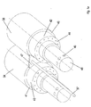
- a shaft 46 of crystallizing rolls 38, 39 has radial openings 45 to feed cooling water, which, through internal non-illustrated passages, is brought to a flange 44 and from here distributed circumferentially on the peripheral of these rolls through special channels that extend internally, parallel to their axis.
- Sections 42, 43 of rolls 38, 39 are not involved in strip forming since they do not come into contact with the liquid steel; shoulders 40, 41 mark the beginning of the zone that is in contact with the liquid steel and the lateral confinement of the steel within this area is guaranteed by a plate 47.
- the cross size of this plate and therefore its surface extension is limited to the above described configuration of crystallizing rolls 38, 39 and depends on the height of shoulders 40, 41.
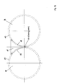
- Figure 1b shows areas 48, 49 of plate 47 that are in sliding contact with the respective shoulders 40, 41 of crystallizing rolls 38, 39 and a minimum distance point 50 between rolls referred to as the "kissing point".
- the plate 47 is made up of a skid 4 in refractory material and number "n" of steel plates P 1 , P 2 , ... , P i , P i+1 , P i+2 , ... , P n spaced in such a way as to leave a suitable space for cooling with inert gas (argon or nitrogen) or, if this gas is not available, to guarantee low heat transfer.
- the plate P 1 is connected to a thrust unit 37, whereas plate P n supports the refractory skid 4. All plates are interconnected by means of fixing elements 12, which could be screws, welded pins or other.
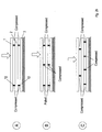
- a staggered distribution of fixing elements 12, illustrated in solution C of figure 2b guarantees the compression of all the elements and at the same time a better distribution of the contact pressure, as there are in fact four pressure peaks.
- each fixing element that connects plate P i to plate P i+1 is provided with at least one pair of fixing elements to connect plate P i+1 to plate P i+2 and that, in reference to any side view of this device, the axis of the fixing elements that connect plate P i to plate P i+1 assumes an intermediate position in the distance between the axes of the corresponding pair of fixing elements that connect plate P i+1 to plate P i+2 , thereby resulting in fixing elements 12 with a basically staggered arrangement.
- Figures 2c and 2d illustrate a first and second embodiment, respectively, depending on the height of shoulders 40, 41.
- V 1,2 the number of fixing elements that connect plate P 1 to plate P 2
- V (i,i+1) that connect plate P i to plate P i+1 2 (i-1) *V 1,2 .
- the oscillating connection between plate P 1 and thrust unit 37 is by means of a ball joint.
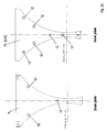
- control rod 7 is connected to plate P 1 by means of bracket 6, connecting pin 8 and ball 5.
- the thrust force supplied through control rod 7 by a hydraulic piston, not illustrated here is applied in correspondence of the ball 5.
- the ball joint is not a traditional type since it does not have the typical intermediate connecting elements (pin and fork).
- the seat of ball 5, in fact, is in the corresponding surfaces on connecting pin 8 and plate P 1 , since connecting pin 8 and plate P 1 are connected to each other by means of fixing plaque 10.
- this manufacturing solution has various advantages: the overall dimensions can be reduced to a minimum and consequently the protection system against oxidation of the liquid bath can be simplified. It allows plate P 1 to be supported even when refractory skid 4 is not in contact with the side of the casting roll, it facilitates lubrication of ball 5, which is done through intake point 9, simplifies maintenance and speeds up replacement thanks to the bevel coupling of connecting pin 8 in bracket 6.
- Another important advantage deriving from the use of this joint is that it moves the application point of the thrust force closer to the sliding surface between refractory skid and casting roll, thereby minimizing the moment applied by the resultant of the frictional force with respect to the center of ball 5.
- Ball 5 allows maximum turning or oscillating freedom of plate P 1 and therefore maximum adaptation possibility of skid 4 on the side of the casting roll.
- an anti-rotation system which in this case is made up of stop 11 integral with control rod 7 that fits into a seat cut 14 into metal plate P 1 .
- the configuration of stop 11 and corresponding seat of the anti-rotation system allows the plate to rotate longitudinally around the center of ball 5 and, furthermore, for any position assumed by the skid during longitudinal rotation, to rotate (transversally to the rolls) around the axis that passes through the center of ball 5 parallel to the new direction taken by plate P 1 .
- Maximum allowable amplitude for both indicated rotations is ⁇ 2 degrees.
- the stop is effectively placed on the longitudinal axis passing through the center of ball 5.
- the stop 11 has a spherical end 20 that fits into the corresponding slotted opening 21 cut into metal plate P 1 .
- the stop is made up of a foil 22 that fits into a corresponding shaped groove 23 with convex profile cut into the plate P 1 .
- the stop is made up of a pin 24 that fits into the corresponding groove 25 cut into the plate P 1 .
- the stop is made up of a fork 26 that holds a pin 27, which fits into a special shaped projection 28 with convex profile cut into plate P 1 .
Landscapes
- Engineering & Computer Science (AREA)
- Mechanical Engineering (AREA)
- Continuous Casting (AREA)
- Rollers For Roller Conveyors For Transfer (AREA)
- Rolls And Other Rotary Bodies (AREA)
Priority Applications (4)
| Application Number | Priority Date | Filing Date | Title |
|---|---|---|---|
| EP01120627A EP1287926B1 (fr) | 2001-08-29 | 2001-08-29 | Dispositif de confinement latéral d'acier liquide entre les rouleaux refroidis d'une machine de coulée de bandes d'acier |
| DE60117438T DE60117438T2 (de) | 2001-08-29 | 2001-08-29 | Seitendammanordnung für flüssigen Stahl zwischen Kühlrollen in einer Giessmaschine |
| AT01120627T ATE318665T1 (de) | 2001-08-29 | 2001-08-29 | Seitendammanordnung für flüssigen stahl zwischen kühlrollen in einer giessmaschine |
| US10/229,569 US6739382B2 (en) | 2001-08-29 | 2002-08-28 | Device for lateral containment of liquid steel between crystallizing rolls of a casting machine for a steel strip |
Applications Claiming Priority (1)
| Application Number | Priority Date | Filing Date | Title |
|---|---|---|---|
| EP01120627A EP1287926B1 (fr) | 2001-08-29 | 2001-08-29 | Dispositif de confinement latéral d'acier liquide entre les rouleaux refroidis d'une machine de coulée de bandes d'acier |
Publications (2)
| Publication Number | Publication Date |
|---|---|
| EP1287926A1 true EP1287926A1 (fr) | 2003-03-05 |
| EP1287926B1 EP1287926B1 (fr) | 2006-03-01 |
Family
ID=8178453
Family Applications (1)
| Application Number | Title | Priority Date | Filing Date |
|---|---|---|---|
| EP01120627A Expired - Lifetime EP1287926B1 (fr) | 2001-08-29 | 2001-08-29 | Dispositif de confinement latéral d'acier liquide entre les rouleaux refroidis d'une machine de coulée de bandes d'acier |
Country Status (4)
| Country | Link |
|---|---|
| US (1) | US6739382B2 (fr) |
| EP (1) | EP1287926B1 (fr) |
| AT (1) | ATE318665T1 (fr) |
| DE (1) | DE60117438T2 (fr) |
Cited By (1)
| Publication number | Priority date | Publication date | Assignee | Title |
|---|---|---|---|---|
| EP1539405B1 (fr) * | 2002-08-27 | 2008-12-10 | DANIELI & C. OFFICINE MECCANICHE S.p.A. | Dispositif de confinement de bain metallique place entre les rouleaux de cristallisation d'une machine de coulee en continu |
Families Citing this family (3)
| Publication number | Priority date | Publication date | Assignee | Title |
|---|---|---|---|---|
| US7556084B2 (en) * | 2006-03-24 | 2009-07-07 | Nucor Corporation | Long wear side dams |
| US8251127B2 (en) * | 2008-06-24 | 2012-08-28 | Nucor Corporation | Strip casting apparatus with independent delivery nozzle and side dam actuators |
| US10046384B2 (en) | 2015-09-30 | 2018-08-14 | Nucor Corporation | Side dam with pocket |
Citations (5)
| Publication number | Priority date | Publication date | Assignee | Title |
|---|---|---|---|---|
| EP0556657A1 (fr) * | 1992-02-17 | 1993-08-25 | Mitsubishi Jukogyo Kabushiki Kaisha | Dispositif de coulée continue entre deux rouleaux |
| GB2296883A (en) * | 1995-01-12 | 1996-07-17 | Ishikawajima Harima Heavy Ind | Strip casting |
| US5584335A (en) * | 1994-06-30 | 1996-12-17 | Usinor-Sacilor | Device for continuous casting between rolls with applied side dams |
| US5638892A (en) * | 1994-06-30 | 1997-06-17 | Usinor-Sacilor | Method and device for continuous casting of thin metals products between rolls |
| GB2337016A (en) * | 1998-05-04 | 1999-11-10 | Ishikawajima Harima Heavy Ind | Pivotting side plates for strip casting rollers |
Family Cites Families (2)
| Publication number | Priority date | Publication date | Assignee | Title |
|---|---|---|---|---|
| FR2727337B1 (fr) * | 1994-11-30 | 1996-12-27 | Usinor Sacilor | Dispositif de support d'une face laterale d'une installation de coulee continue de bandes metalliques entre cylindres |
| FR2737859B1 (fr) * | 1995-08-18 | 1997-09-12 | Usinor Sacilor | Dispositif de soutien d'une face laterale d'une installation de coulee continue de bandes metalliques entre cylindres |
-
2001
- 2001-08-29 AT AT01120627T patent/ATE318665T1/de not_active IP Right Cessation
- 2001-08-29 EP EP01120627A patent/EP1287926B1/fr not_active Expired - Lifetime
- 2001-08-29 DE DE60117438T patent/DE60117438T2/de not_active Expired - Lifetime
-
2002
- 2002-08-28 US US10/229,569 patent/US6739382B2/en not_active Expired - Fee Related
Patent Citations (5)
| Publication number | Priority date | Publication date | Assignee | Title |
|---|---|---|---|---|
| EP0556657A1 (fr) * | 1992-02-17 | 1993-08-25 | Mitsubishi Jukogyo Kabushiki Kaisha | Dispositif de coulée continue entre deux rouleaux |
| US5584335A (en) * | 1994-06-30 | 1996-12-17 | Usinor-Sacilor | Device for continuous casting between rolls with applied side dams |
| US5638892A (en) * | 1994-06-30 | 1997-06-17 | Usinor-Sacilor | Method and device for continuous casting of thin metals products between rolls |
| GB2296883A (en) * | 1995-01-12 | 1996-07-17 | Ishikawajima Harima Heavy Ind | Strip casting |
| GB2337016A (en) * | 1998-05-04 | 1999-11-10 | Ishikawajima Harima Heavy Ind | Pivotting side plates for strip casting rollers |
Cited By (1)
| Publication number | Priority date | Publication date | Assignee | Title |
|---|---|---|---|---|
| EP1539405B1 (fr) * | 2002-08-27 | 2008-12-10 | DANIELI & C. OFFICINE MECCANICHE S.p.A. | Dispositif de confinement de bain metallique place entre les rouleaux de cristallisation d'une machine de coulee en continu |
Also Published As
| Publication number | Publication date |
|---|---|
| ATE318665T1 (de) | 2006-03-15 |
| US20030041997A1 (en) | 2003-03-06 |
| DE60117438D1 (de) | 2006-04-27 |
| US6739382B2 (en) | 2004-05-25 |
| DE60117438T2 (de) | 2006-11-16 |
| EP1287926B1 (fr) | 2006-03-01 |
Similar Documents
| Publication | Publication Date | Title |
|---|---|---|
| US5887644A (en) | Roll cooling structure for twin roll continuous caster | |
| US3965974A (en) | Continuous casting plant | |
| US5996680A (en) | Twin roll casting | |
| EP1287926B1 (fr) | Dispositif de confinement latéral d'acier liquide entre les rouleaux refroidis d'une machine de coulée de bandes d'acier | |
| CA1084233A (fr) | Galet de guidage pour convoyeur de coulee continue | |
| EP0955112B1 (fr) | Coulée continue de bande en acier | |
| CN114535526A (zh) | 一种具有多通道冷却回路的扇形段足辊 | |
| ES2200937T3 (es) | Maquina de fundicion de banda para la generacion de una banda metalica. | |
| JPH1163846A (ja) | 竪形炉用冷却板 | |
| AU2001289934B2 (en) | Cooling element for shaft furnaces | |
| EP3041620B1 (fr) | Ensemble de lignes de rouleaux pour une coulée continue | |
| CA1061986A (fr) | Methode et appareil pour la coulee continue de brames d'acier | |
| JPS6160245A (ja) | 複ベルト式連鋳鋳型の鋳込みベルト用ガイド装置 | |
| KR101449253B1 (ko) | 연속 주조용 가이드 롤 | |
| CN116422848B (zh) | 一种独立冷却、多节组合结构的连铸机扇形段从动辊 | |
| KR101372591B1 (ko) | 세그먼트용 다분할 핀치롤 | |
| CN103223476A (zh) | 连续浇注连铸坯的直通式结晶器 | |
| JP4074973B2 (ja) | 厚み圧下プレス用金型 | |
| EP2127778A1 (fr) | Procédé de fonctionnement pour une machine de coulée à cylindres jumelés, et dispositif de support de déversoir latéral | |
| AU738831B2 (en) | Twin roll casting | |
| JPS6121162Y2 (fr) | ||
| JPH0481250A (ja) | 薄板連続鋳造機のサイド堰潤滑方法 | |
| JP3440957B2 (ja) | 水冷ジャケット樋 | |
| JPS6326241A (ja) | 金属薄板帯の直接鋳造装置 | |
| JP3857823B2 (ja) | 双ドラム式薄板連続鋳造装置用の冷却ドラム |
Legal Events
| Date | Code | Title | Description |
|---|---|---|---|
| PUAI | Public reference made under article 153(3) epc to a published international application that has entered the european phase |
Free format text: ORIGINAL CODE: 0009012 |
|
| AK | Designated contracting states |
Kind code of ref document: A1 Designated state(s): AT BE CH CY DE DK ES FI FR GB GR IE IT LI LU MC NL PT SE TR |
|
| AX | Request for extension of the european patent |
Extension state: AL LT LV MK RO SI |
|
| 17P | Request for examination filed |
Effective date: 20030519 |
|
| AKX | Designation fees paid |
Designated state(s): AT DE FR IT |
|
| GRAP | Despatch of communication of intention to grant a patent |
Free format text: ORIGINAL CODE: EPIDOSNIGR1 |
|
| GRAS | Grant fee paid |
Free format text: ORIGINAL CODE: EPIDOSNIGR3 |
|
| GRAA | (expected) grant |
Free format text: ORIGINAL CODE: 0009210 |
|
| AK | Designated contracting states |
Kind code of ref document: B1 Designated state(s): AT DE FR IT |
|
| REF | Corresponds to: |
Ref document number: 60117438 Country of ref document: DE Date of ref document: 20060427 Kind code of ref document: P |
|
| ET | Fr: translation filed | ||
| PLBE | No opposition filed within time limit |
Free format text: ORIGINAL CODE: 0009261 |
|
| STAA | Information on the status of an ep patent application or granted ep patent |
Free format text: STATUS: NO OPPOSITION FILED WITHIN TIME LIMIT |
|
| 26N | No opposition filed |
Effective date: 20061204 |
|
| PGFP | Annual fee paid to national office [announced via postgrant information from national office to epo] |
Ref country code: FR Payment date: 20080828 Year of fee payment: 8 |
|
| PGFP | Annual fee paid to national office [announced via postgrant information from national office to epo] |
Ref country code: AT Payment date: 20090724 Year of fee payment: 9 |
|
| REG | Reference to a national code |
Ref country code: FR Ref legal event code: ST Effective date: 20100430 |
|
| PG25 | Lapsed in a contracting state [announced via postgrant information from national office to epo] |
Ref country code: FR Free format text: LAPSE BECAUSE OF NON-PAYMENT OF DUE FEES Effective date: 20090831 |
|
| PG25 | Lapsed in a contracting state [announced via postgrant information from national office to epo] |
Ref country code: AT Free format text: LAPSE BECAUSE OF NON-PAYMENT OF DUE FEES Effective date: 20100829 |
|
| PGFP | Annual fee paid to national office [announced via postgrant information from national office to epo] |
Ref country code: DE Payment date: 20170719 Year of fee payment: 17 |
|
| PGFP | Annual fee paid to national office [announced via postgrant information from national office to epo] |
Ref country code: IT Payment date: 20180719 Year of fee payment: 18 |
|
| REG | Reference to a national code |
Ref country code: DE Ref legal event code: R119 Ref document number: 60117438 Country of ref document: DE |
|
| PG25 | Lapsed in a contracting state [announced via postgrant information from national office to epo] |
Ref country code: DE Free format text: LAPSE BECAUSE OF NON-PAYMENT OF DUE FEES Effective date: 20190301 |
|
| PG25 | Lapsed in a contracting state [announced via postgrant information from national office to epo] |
Ref country code: IT Free format text: LAPSE BECAUSE OF NON-PAYMENT OF DUE FEES Effective date: 20190829 |