EP1287971A2 - Durch Längs- und Querrfasern verstärktes, pultrudiertes Teil und Verfahren zu seiner Herstellung - Google Patents
Durch Längs- und Querrfasern verstärktes, pultrudiertes Teil und Verfahren zu seiner Herstellung Download PDFInfo
- Publication number
- EP1287971A2 EP1287971A2 EP02254153A EP02254153A EP1287971A2 EP 1287971 A2 EP1287971 A2 EP 1287971A2 EP 02254153 A EP02254153 A EP 02254153A EP 02254153 A EP02254153 A EP 02254153A EP 1287971 A2 EP1287971 A2 EP 1287971A2
- Authority
- EP
- European Patent Office
- Prior art keywords
- fibres
- layer
- wall
- resin
- transverse
- Prior art date
- Legal status (The legal status is an assumption and is not a legal conclusion. Google has not performed a legal analysis and makes no representation as to the accuracy of the status listed.)
- Granted
Links
Images


Classifications
-
- B—PERFORMING OPERATIONS; TRANSPORTING
- B29—WORKING OF PLASTICS; WORKING OF SUBSTANCES IN A PLASTIC STATE IN GENERAL
- B29C—SHAPING OR JOINING OF PLASTICS; SHAPING OF MATERIAL IN A PLASTIC STATE, NOT OTHERWISE PROVIDED FOR; AFTER-TREATMENT OF THE SHAPED PRODUCTS, e.g. REPAIRING
- B29C70/00—Shaping composites, i.e. plastics material comprising reinforcements, fillers or preformed parts, e.g. inserts
- B29C70/04—Shaping composites, i.e. plastics material comprising reinforcements, fillers or preformed parts, e.g. inserts comprising reinforcements only, e.g. self-reinforcing plastics
- B29C70/06—Fibrous reinforcements only
- B29C70/08—Fibrous reinforcements only comprising combinations of different forms of fibrous reinforcements incorporated in matrix material, forming one or more layers, and with or without non-reinforced layers
- B29C70/083—Combinations of continuous fibres or fibrous profiled structures oriented in one direction and reinforcements forming a two dimensional structure, e.g. mats
-
- B—PERFORMING OPERATIONS; TRANSPORTING
- B29—WORKING OF PLASTICS; WORKING OF SUBSTANCES IN A PLASTIC STATE IN GENERAL
- B29C—SHAPING OR JOINING OF PLASTICS; SHAPING OF MATERIAL IN A PLASTIC STATE, NOT OTHERWISE PROVIDED FOR; AFTER-TREATMENT OF THE SHAPED PRODUCTS, e.g. REPAIRING
- B29C70/00—Shaping composites, i.e. plastics material comprising reinforcements, fillers or preformed parts, e.g. inserts
- B29C70/04—Shaping composites, i.e. plastics material comprising reinforcements, fillers or preformed parts, e.g. inserts comprising reinforcements only, e.g. self-reinforcing plastics
- B29C70/06—Fibrous reinforcements only
- B29C70/08—Fibrous reinforcements only comprising combinations of different forms of fibrous reinforcements incorporated in matrix material, forming one or more layers, and with or without non-reinforced layers
- B29C70/081—Combinations of fibres of continuous or substantial length and short fibres
-
- B—PERFORMING OPERATIONS; TRANSPORTING
- B29—WORKING OF PLASTICS; WORKING OF SUBSTANCES IN A PLASTIC STATE IN GENERAL
- B29C—SHAPING OR JOINING OF PLASTICS; SHAPING OF MATERIAL IN A PLASTIC STATE, NOT OTHERWISE PROVIDED FOR; AFTER-TREATMENT OF THE SHAPED PRODUCTS, e.g. REPAIRING
- B29C70/00—Shaping composites, i.e. plastics material comprising reinforcements, fillers or preformed parts, e.g. inserts
- B29C70/04—Shaping composites, i.e. plastics material comprising reinforcements, fillers or preformed parts, e.g. inserts comprising reinforcements only, e.g. self-reinforcing plastics
- B29C70/28—Shaping operations therefor
- B29C70/40—Shaping or impregnating by compression not applied
- B29C70/50—Shaping or impregnating by compression not applied for producing articles of indefinite length, e.g. prepregs, sheet moulding compounds [SMC] or cross moulding compounds [XMC]
- B29C70/52—Pultrusion, i.e. forming and compressing by continuously pulling through a die
- B29C70/525—Component parts, details or accessories; Auxiliary operations
-
- Y—GENERAL TAGGING OF NEW TECHNOLOGICAL DEVELOPMENTS; GENERAL TAGGING OF CROSS-SECTIONAL TECHNOLOGIES SPANNING OVER SEVERAL SECTIONS OF THE IPC; TECHNICAL SUBJECTS COVERED BY FORMER USPC CROSS-REFERENCE ART COLLECTIONS [XRACs] AND DIGESTS
- Y10—TECHNICAL SUBJECTS COVERED BY FORMER USPC
- Y10T—TECHNICAL SUBJECTS COVERED BY FORMER US CLASSIFICATION
- Y10T428/00—Stock material or miscellaneous articles
- Y10T428/13—Hollow or container type article [e.g., tube, vase, etc.]
- Y10T428/1352—Polymer or resin containing [i.e., natural or synthetic]
- Y10T428/139—Open-ended, self-supporting conduit, cylinder, or tube-type article
-
- Y—GENERAL TAGGING OF NEW TECHNOLOGICAL DEVELOPMENTS; GENERAL TAGGING OF CROSS-SECTIONAL TECHNOLOGIES SPANNING OVER SEVERAL SECTIONS OF THE IPC; TECHNICAL SUBJECTS COVERED BY FORMER USPC CROSS-REFERENCE ART COLLECTIONS [XRACs] AND DIGESTS
- Y10—TECHNICAL SUBJECTS COVERED BY FORMER USPC
- Y10T—TECHNICAL SUBJECTS COVERED BY FORMER US CLASSIFICATION
- Y10T428/00—Stock material or miscellaneous articles
- Y10T428/24—Structurally defined web or sheet [e.g., overall dimension, etc.]
- Y10T428/24058—Structurally defined web or sheet [e.g., overall dimension, etc.] including grain, strips, or filamentary elements in respective layers or components in angular relation
- Y10T428/24124—Fibers
-
- Y—GENERAL TAGGING OF NEW TECHNOLOGICAL DEVELOPMENTS; GENERAL TAGGING OF CROSS-SECTIONAL TECHNOLOGIES SPANNING OVER SEVERAL SECTIONS OF THE IPC; TECHNICAL SUBJECTS COVERED BY FORMER USPC CROSS-REFERENCE ART COLLECTIONS [XRACs] AND DIGESTS
- Y10—TECHNICAL SUBJECTS COVERED BY FORMER USPC
- Y10T—TECHNICAL SUBJECTS COVERED BY FORMER US CLASSIFICATION
- Y10T428/00—Stock material or miscellaneous articles
- Y10T428/249921—Web or sheet containing structurally defined element or component
- Y10T428/249924—Noninterengaged fiber-containing paper-free web or sheet which is not of specified porosity
- Y10T428/249928—Fiber embedded in a ceramic, glass, or carbon matrix
- Y10T428/249929—Fibers are aligned substantially parallel
- Y10T428/24993—Fiber is precoated
-
- Y—GENERAL TAGGING OF NEW TECHNOLOGICAL DEVELOPMENTS; GENERAL TAGGING OF CROSS-SECTIONAL TECHNOLOGIES SPANNING OVER SEVERAL SECTIONS OF THE IPC; TECHNICAL SUBJECTS COVERED BY FORMER USPC CROSS-REFERENCE ART COLLECTIONS [XRACs] AND DIGESTS
- Y10—TECHNICAL SUBJECTS COVERED BY FORMER USPC
- Y10T—TECHNICAL SUBJECTS COVERED BY FORMER US CLASSIFICATION
- Y10T428/00—Stock material or miscellaneous articles
- Y10T428/249921—Web or sheet containing structurally defined element or component
- Y10T428/249924—Noninterengaged fiber-containing paper-free web or sheet which is not of specified porosity
- Y10T428/24994—Fiber embedded in or on the surface of a polymeric matrix
- Y10T428/249942—Fibers are aligned substantially parallel
- Y10T428/249946—Glass fiber
-
- Y—GENERAL TAGGING OF NEW TECHNOLOGICAL DEVELOPMENTS; GENERAL TAGGING OF CROSS-SECTIONAL TECHNOLOGIES SPANNING OVER SEVERAL SECTIONS OF THE IPC; TECHNICAL SUBJECTS COVERED BY FORMER USPC CROSS-REFERENCE ART COLLECTIONS [XRACs] AND DIGESTS
- Y10—TECHNICAL SUBJECTS COVERED BY FORMER USPC
- Y10T—TECHNICAL SUBJECTS COVERED BY FORMER US CLASSIFICATION
- Y10T428/00—Stock material or miscellaneous articles
- Y10T428/249921—Web or sheet containing structurally defined element or component
- Y10T428/249924—Noninterengaged fiber-containing paper-free web or sheet which is not of specified porosity
- Y10T428/24994—Fiber embedded in or on the surface of a polymeric matrix
- Y10T428/24995—Two or more layers
- Y10T428/249952—At least one thermosetting synthetic polymeric material layer
Definitions
- This invention relates to a pultruded part reinforced by longitudinal and transverse fibers and a method of manufacturing the part.
- Pultrusion is a technique in which longitudinally continuous fibrous structures are used to pull a resin through a die so that the resin sets and produces a rigid part downstream of the die to which the pulling force is applied.
- transverse fibers to provide strength in the transverse direction.
- Such transverse fibers are conventionally applied using a mat of a woven or non woven material. In many cases the fibers in the mat are generally random so that the number of fibers extending in the transverse direction is relatively small.
- One major problem with the mat is that it is relatively expensive and can be very expensive so that it is more than double per pound of the cost of the simple conventional rovings.
- polyester which is a simple thermo-set resin material so that it can be applied to the fibers from a bath and is thermo-set within the heated die.
- polyester is a linear polymer which is thus not cross-linked so that it is relatively brittle so that it tends to crack when bending forces are applied to the part. This cracking is reduced by providing in the reinforcing fibers a mat material at the surface of the wall of the part so that the fibers are held in place by the transverse fibers, This avoids or reduces the tendency of the longitudinal fibers to break through the surface of the part on bending of the part.
- polyester resin parts have required that the mat be applied on the outside surface.
- a mat is applied on the surface of each wall of the part so that there is a mat on the outside and also a mat on the inside surface with the normal longitudinal fibers or rovings being placed in between the two mats.
- This construction significantly increases the cost of the part in that the mat is relatively expensive and two mats are required. Also the provision of two mats increases the thickness of the part and thus again increases material costs.
- Non-linear resins which may be cross-linked or amorphous such as epoxy resins, have been available for some years and are used in pultrusion; but these are significantly more expensive than polyester and thus have not achieved significant market penetration in conventional simple parts for which pultrusion is ideally suited.
- Mats for reinforcing pultruded parts are provided to add structural strength and in order to provide the required or expected amount of strength have a weight of fibers greater than 0.5 ounces per square foot and generally 0.75 to 1.0 ounces per square foot
- Veils which are used to provide surface characteristics and not to provide any structural strength are lighter, generally less than 0.5 ounces per square foot and typically of the order of 0.1 ounces per square foot.
- Conventional veils are used outside rovings or outside mats at the surface to provide an improved surface appearance or to retain the stiffer glass fibers within the resin to prevent fiber "bloom" or projecting fibers which can act as slivers. This latter requirement to prevent slivers is particularly important in tool handles or similar products. The retention of fibers to prevent weathering or bloom is particularly important in fenestration or similar products.
- Veils are well known and well used, when required for the part concerned, by persons skilled in this art and are not intended to form part of and are not considered as part of the fiber reinforcement.
- a pultruded part comprising:
- the longitudinal fibers referred to herein are usually glass rovings as these are inexpensive and widely available in a range of yields.
- the present invention is not limited to rovings and other longitudinal bulk fibers may be used or may become available.
- the reference to fibers extending both in the longitudinal pultrusion direction and transverse to the longitudinal direction is intended to include any type of mat or veil structure where the fibers are not wholly longitudinal.
- Other types of mat structure can also be included provided there is some transverse component of the fibers and provided the structure satisfies the other features as defined herein.
- the reinforcing fibers are stated to be at or substantially at the surface, this is intended to include situations where the conventional surface veil of surface fibers is included or is not included. In some cases the surface veil is used to provide surface characteristics as is well known and the definition referred to herein assumes that this can be selected for use or not without significantly affecting the fiber reinforcement effects provided by the main body of the reinforcing fibers.
- the wall defines a peripheral wall fully surrounding a hollow interior such that the first surface faces outwardly of the hollow interior and the second surface faces inwardly toward the hollow interior
- the at least one first layer of fibers consists solely of a first layer of reinforcing fibers located substantially at the first surface and said one or more second layer of fibers are reinforcing fibers and consists solely of a second layer of reinforcing fibers located at the second surface.
- the at least one first layer of fibers includes one first layer of reinforcing fibers located substantially at the first surface and another first layer of reinforcing fibers located substantially at the second surface and said one or more second layer of fibers comprises a layer of reinforcing fibers which is located intermediate said one first layer and said another first layer.
- the resin is a urethane resin although other resins can be used provided they cross-link which allows the fibers to be located at the surface without the fibers cracking through the surface.
- Such resins are often known as multi-functional resins, referring to the operation of the polymers at molecular level as "multi-functional”.
- the resin is a two part material set by catalytic action and is thermo-set.
- other resins can also be used
- the fibers of the intermediate layer form fibers of a pre-formed mat which may be of a conventional construction defined by random continuous fibers bonded or needle punched for connection.
- the mat may also be of the construction shown in the above published International Application assigned to Pella Corporation and on which one of the present inventors Davies is one of the named inventors.
- the intermediate layer of fibers comprises a plurality of cut fibers which are unsupported by mat fibers and are applied onto the second layer of fibers to be carried thereby.
- the intermediate layer of fibers preferably consist wholly cut fibers.
- the intermediate layer of fibers comprises primarily and preferably wholly straight fibers extending transverse to the longitudinal direction fully across the width of the part from one side to the other side.
- the reinforcing fibers consist only of the first layer, the second layer and the intermediate layer.
- the transverse layer has a weight of less than 1 oz/square foot preferably less than 0.5 oz/square foot and more preferably less than 0.25 oz/square foot and more preferably still of the order of 0.1 ounces per square foot, since it has been found that the provision of increased amounts of fiber can interfere with the cross-linking of the resin and thus provide a decreased strength rather than the increase which would normally be expected with conventional resins.
- the transverse layer may be a scrim or mesh having openings for penetration of the resin between the fibers so as to allow effective cross-linking of the resin. It has also been found that surprisingly a veil of staple polyester fibers having a weight of as low as 0.1 oz/square foot can provide the required additional strength and/or toughness to the product.
- the transverse or intermediate layer may be formed of any suitable fibers including but not limited to glass fibers, carbon fibers polymer fibers such as polyester or aramids, metal strands such as aluminum or steel or natural fibers such as cotton, jute, hemp or flax.
- Natural fibers such as flax have the advantage that they are inexpensive and are to some extent porous thus allowing the resin to enter the interstices in the fibers and providing an increased bond between the fibers and the resin which can lead to reduced de-lamination and thus increased strength.
- Metal strands have the advantage that they provide the required additional strength and/or toughness in the intermediate layer, but also they can provide other functions such as the required ferromagnetic effect for magnetic coupling as shown for example in US Patent 5,129,184 (Fish) issued July 14, 1992 and/or an electrostatic charging effect for electrostatic deposition of a coating or paint material.
- the wall may include a leg portion thereof in which the reinforcing fibers consist solely of the longitudinal fibers, that is there is no transverse fibers.
- the leg such as a glazing leg of a window profile has a length greater than 0.5 inches which would normally require transverse reinforcement but a length less than about 1.0 inches where there is insufficient bending moment in the leg itself to allow cracking in the leg to occur.
- the bending effect at an angle is different from that within a span of the material.
- the provision of transverse fibers within a leg or span of greater than 1.0 inches in length is required while such fibers are not necessary at an angle between two legs of shorter length.
- the leg portion may have a wall that is thicker than that of the main body portion; but this is provided for balancing of forces in the pultrusion process rather than in order to provide increased strength to compensate for the absence of the mat or transverse fibers.
- the main body portion defines a hollow section and the leg portion, generally a glazing leg, extends from one end at the hollow section to an opposed free end.
- the urethane resin used preferably in the embodiments described hereinafter has the advantage that it is more resistant to degradation by UV and weather so that it is more suitable for fenestration products.
- the construction described in the embodiments hereinafter also may have the advantage that it allows a reduced wall thickness.
- the use, in lower strength products such as fenestration products, conventionally of two outside perimeter mats can be reduced by one mat from two mats to one mat so that the total thickness can be reduced by at least 0.015 inch, which is the typical thickness of one mat.
- the increased strength in the resin itself may allow a further reduction so that typically a conventional range in inches of polyester resin construction of 0.070 to 0.180 for different end uses can be reduced to a range of 0.030 to 0.120.
- a thickness even as low as 0.025 may also be possible for products such as fenestration products which require lower structural strength and a thickness of the order of 0.080 may be possible for products such as ladder rails or tool handles which require higher structural strength.
- the higher strength structural products often include a third mat along the centre and thus the three mats of the conventional product can be reduced to one mat or veil in the arrangement described above thus yet further reducing the thickness.
- This reduction in mat content also increases the proportion of longitudinal fibres or rovings and this also has the advantage that the longitudinal stiffness of the part as provided by the longitudinal fibres is also increased.
- a ladder rail may be reduced typically in thickness from 0.125 to 0.105 inch with an increase in strength.
- the transverse fibres are formed of metal strands which provide both transverse strength and the characteristic of electrical conductivity and/or ferromagnetism for the part.
- a pultruded part comprising:
- a pultruded part comprising:
- Table 1 is a list of the materials tested in Figures 8 and 9.
- Figure 1 a typical cross section of a pultruded part which includes a hollow section 10, a leg 11 and a projecting portion 12.
- the hollow section 10 includes four walls 10A, 10B, 10C and 10D each of which has a thickness between an outer surface 10E and an inner surface 10F.
- each wall part of the pultrusion must be manufactured in a manner which provides the necessary strength to prevent cracking of the part.
- Figures 2 and 3 a cross section of one wall of the part which is cut to form an end face 13. These cross sections show that the wall of the part is formed from a resin 14 which is shaped to define the surfaces 10E and 10F and a volume of the part is defined by a resin material 15 which is interspersed between or permeated through fibre reinforcement 15 within the part.
- the fibre reinforcement includes a first layer 16 of longitudinally extending fibres, primarily rovings, a second layer 17 also of longitudinally extending rovings and an intermediate layer 18 of fibres arranged to provide transverse strength.
- the resin which extends through the part so that it defines the two surfaces of the part is a urethane resin available from Resin Systems Inc. of Edmonton, Alberta and is defined by a two-part resin which includes a catalyst for activating the resin.
- the particularly preferred resin is known as Version G available from the above company which has the following characteristics:
- Figures 4 and 5 is shown schematically a method for using the resin for application to the reinforcing fibres to form the part of Figure 1.
- the longitudinal fibres 16 are supplied from roving bobbins 16A to define a layer of the rovings arranged substantially side by side which are carried forwardly through the pre-shaper 20 and the resin injection system 21 into the die 22 by a pulling system schematically indicated at 23 downstream of the die.
- the layer 16 forms a band, it can act as a conveyor carrying fibres forming the intermediate layer 18 into the same elements for forming the pultruded part.
- the intermediate layer 18 is covered by the upper layer 17 again formed from rovings supplied from roving bobbins 17A thus the intermediate fibres are protected and encapsulated as they are carried into the pultrusion system between the two layers 16 and 17.
- the pre-shaper 20 can therefore be of a simple construction which causes the band defined by the three layers to be shaped into the required shape to enter into the die to form the construction shown in cross section in Figure 1.
- the construction of the pre-shaper will be well known to one skilled in the art and therefore does not require detailed explanation here.
- the resin injection arrangement is designed for use with the two-part resin material described above and therefore there are two supplies supply 1 and supply 2 which are pumped from a container via two separate pumps into a mixer immediately upstream of the resin injection system.
- the materials are therefore mixed for only a short period of time before the resin is injected into the dry fibres so as to permeate through the fibres and to be carried by the fibres into the die.
- the details of the mixer valve and the resin injection system are again well known to one skilled in the art and provide the necessary controls for varying the mix proportions and for ensuring that the required amount of resin is maintained within the injection system.
- transverse fibre layer 18 is protected within the two layers 16 and 17, it is possible to supply the transverse fibre layer either as a pre-formed mat or as individual chopped fibres. Pre-formed mat is relatively expensive since it involves an additional process and this may double or triple the base material costs.
- a cut fibre supply device 25 which receives fibres from yarn or roving supplies 26 and chops those fibres into fibre strands 27 laid across the width of the layer 16 defined by the rovings 16A. These fibres can thus be laid loosely across the layer 16 since they will be covered by the layer 17 supplied from the rovings 17A at a guide roller R.
- the fibres of the intermediate layer can be added by mixing cut fibres with the resin material and injecting the resin between the roving layers so that the resin permeates through the roving layers while leaving the cut fibres between the rovings.
- Such cut fibres can be introduced to the resin during the mixing stage and can pass through the pump with the resin into the die block as described herein.
- the rovings carry the cut fibres, or other fibres of the intermediate layer however they are introduced, there is no problem of the intermediate layer skewing as it enters the die and no requirement therefore for anti-skewing arrangements within the intermediate layer. It will be appreciated that the application of cut fibres has significantly less structural stability than even the thin mats and veils described herein and yet even these cut fibres can be introduced without skewing or other breakdown of the layer becoming a problem.
- the intention is therefore to provide fibres which extend with their direction primarily or wholly across the width of the layer 16 so as to avoid the necessity for additional fibre elements within the layer 18 which do not contribute to the transfer strength.
- the supply element 25 therefore forms in effect a gun which fires the fibres onto the layer 16 but without sufficient force to disturb the layer 16.
- Conventional chopping guns can be used for this purpose or a gun can be designed which fires the fibres across the width of the layer 16 so that they are cut only when they reach across the full width thus laying them across the full width as shown in Figure 5.
- the intermediate layer is formed simply from a mat pre-formed using conventional materials.
- the fibres of the intermediate layer can be formed from glass using relatively thick or coarse fibres for strength or can be fine glass fibres of the type normally formed to provide a veil.
- the fibre layer normally has a weight less than 1.0 ounce per square foot. Other such mats may have a weight of the order of 0.5 ounces per square foot.
- the lightweight veil material formed of fine glass fibres generally has a weight of the order of 0.25 ounces per square foot.
- An alternative material which can be used is a polyester veil material which is formed by staple fibres of fine polyester in a mat which can be heat bonded using high and low melt fibres in the polyester mat.
- a mat may have a weight less than 0.25 ounces per square foot and preferably of the order of which is equal to 0.1 ounces per square foot ( 30 grams per square meter).
- structural mats that is a mat which contributes to the structural strength of the part have a weight greater than 0.5 ounces per square foot and generally much heavier such as 0.75 to 1.0 ounces per square foot.
- Veils which are lighter than 0.5 ounces per square foot are known but are not used for structural strength, instead being used as a conventional veil which is used to provide required surface characteristics.
- Figure 8 is shown a graph of the results from a first series of different trials of materials 1 to 8 shown in table 1. The results are based upon a standard ASTM coupon test identified as ASTM D790:
- Figure 9 is shown a table of results from a second series of different trials of the same materials from table 1. The results are based upon test of right angle pieces formed from the materials set out in Table 1 where the strength to break was determined by bending the angle piece in a direction to increase the angle from the nominal 90 degrees to breaking of the part. It will be noted that materials 9 and 10 in Table 1 were not used in the tests of Figure 8.
- Figure 10 is shown a table of results from a series of trials of the materials from identified at the bottom of the figure. The results are based upon test of right angle pieces where the strength to break was determined by bending the angle piece in a direction to increase the angle from the nominal 90 degrees to breaking of the part.
- polyyester are of a conventional nature using the conventional resin.
- Those marked “RSI” use the resin of the present invention. Where a percentage is given, this relates to the percentage of filler material.
- “920” “Nico” and “OCF” all relate to particularly types of mat as explained hereinbefore.
- the urethane resin of RSI in the absence of transverse fibres does not have sufficient strength or toughness in wall widths greater than of the order of 1.0 inches to match the required strengths for the required parts. It is necessary therefore to add the transverse fibres when the wall width is greater than of the order of 1.0 inch in order to provide this necessary strength or toughness.
- the strength of the resin alone in conjunction with solely the longitudinal fibres is sufficient to provide the required strength or toughness for the leg to prevent cracking of the leg within its width or at the angle joint with the remainder of the part.
- the wall width such as the walls 10A and 10B in Figure 7 have a greater width which can be as much as 2 to 3 inches, it is necessary to provide the transverse fibres to provide the necessary strength against fracturing during bowing of the wall.
- the thickness of the leg may be increased so that it is at least 10% thicker and may be as much as approximately double the thickness of the walls 10A and 10B.
- transverse fibres do not lead to an increase in the transverse strength. It is believed that this occurs due to the fact that the presence of the transverse fibres inhibits the formation of cross linking within the resin so that the presence of the fibres does not make up for the absence of cross linking.
- the structure can de-laminate under inter-laminar shear at the transverse fibres when bending particularly at a junction for example between the leg 11 and the wall 10A.
- the arrangement of the present invention preferably uses a minimum quantity of transverse fibres which are necessary to provide for the resin the increase in strength for the walls 10A and 10B to match conventional strengths. This reduces the tendency to de-laminate under inter-laminar shear which could otherwise occur where thicker layers of transverse fibres or mats and used.
- mat layer indicated at 18N is located on the inside surface of each of the walls 10A, 10B, etc.
- the mat forms the innermost layer and the remainder of the wall is reinforced by the conventional longitudinal fibres indicated at 17N.
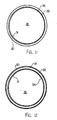
- Figures 11 and 12 is shown a simple tubular pultruded product of for example circular cross section defining a cylindrical outer surface 30 and a cylindrical inner surface 31 surrounding a hollow interior 32.
- the product is pultruded to provide a wall having a wall thickness defined between the inner and outer surfaces which is substantially the same as that previously described.
- the wall is formed by the resin which impregnates the reinforcing fibres as previously described so the resin in effect defines the inner and outer surfaces with the fibres embedded therein.
- the main body of the part is formed from a layer of reinforcing fibres 33 which contains only longitudinal continuous fibres formed by rovings in the conventional manner.
- a second layer 34 at the inner surface 31 is defined by a veil having a thickness as previously described and preferably of the order of .1 ounces per square foot.
- the embodiment shown in Figure 12 is substantially identical with the exception that an additional conventional layer 35 is applied onto the outside surface of the fibres of the layer 33 to form a surface veil covering the fibres and holding them retained within the resin.
- the veil material on the outside surface is intended simply as a surface veil without significantly contributing to the reinforcing effect.
- the veil material on the inside surface while it is of the same thickness and same structure as the veil on the outside surface, does significantly contribute to the reinforcing fibres and provides a product which has sufficient strength to satisfy the market for conventional pultruded products of this general type.
- the embodiment can include the surface veil or not include the surface veil as required by the characteristics of the part and the end use of the part.
- the material on the inside surface provides a significant reinforcing effect and cannot be omitted.
- a part which includes a surface veil on the outside surface but no such reinforcing veil material on the inside surface is unsuitable and unsatisfactory and does not provide the required strength.
- Sample Description 1 OCF mat, Polyester resin, regular process 2 Nico mat, Polyester resin, regular process 3 No mat - all roving, RSI resin 4 Fibermesh, RSI resin, Roving-mat-roving matrix 5 Nico mat, RSI resin, Roving-mat-roving matrix 6 OCF mat, RSI resin, Roving-mat-roving matrix 7 Polyester veil, RSI resin, Raving-mat roving matrix 8 Omnimat, RSI resin, Roving-mat-roving matrix 9 Aluminum mesh, RSI resin, Roving-mat-roving matrix 10 Steel mesh, RSI resin, Roving-mat-roving matrix
Landscapes
- Chemical & Material Sciences (AREA)
- Engineering & Computer Science (AREA)
- Composite Materials (AREA)
- Mechanical Engineering (AREA)
- Moulding By Coating Moulds (AREA)
- Laminated Bodies (AREA)
Priority Applications (1)
| Application Number | Priority Date | Filing Date | Title |
|---|---|---|---|
| EP07075569A EP1842657A3 (de) | 2001-06-14 | 2002-06-13 | Durch Längs- und Querfasern verstärktes pultrudiertes Element und Herstellungsverfahren dafür |
Applications Claiming Priority (4)
| Application Number | Priority Date | Filing Date | Title |
|---|---|---|---|
| US32578501P | 2001-06-14 | 2001-06-14 | |
| US325785P | 2001-06-14 | ||
| US10/024,337 US20030003265A1 (en) | 2001-06-14 | 2001-12-21 | Pultruded part reinforced by longitudinal and transverse fibers and a method of manufacturing thereof |
| US24337 | 2001-12-21 |
Related Child Applications (1)
| Application Number | Title | Priority Date | Filing Date |
|---|---|---|---|
| EP07075569A Division EP1842657A3 (de) | 2001-06-14 | 2002-06-13 | Durch Längs- und Querfasern verstärktes pultrudiertes Element und Herstellungsverfahren dafür |
Publications (3)
| Publication Number | Publication Date |
|---|---|
| EP1287971A2 true EP1287971A2 (de) | 2003-03-05 |
| EP1287971A3 EP1287971A3 (de) | 2003-06-18 |
| EP1287971B1 EP1287971B1 (de) | 2007-08-01 |
Family
ID=26698335
Family Applications (1)
| Application Number | Title | Priority Date | Filing Date |
|---|---|---|---|
| EP02254153A Expired - Lifetime EP1287971B1 (de) | 2001-06-14 | 2002-06-13 | Durch Längs- und Querrfasern verstärktes, pultrudiertes Teil |
Country Status (5)
| Country | Link |
|---|---|
| US (2) | US20030003265A1 (de) |
| EP (1) | EP1287971B1 (de) |
| AT (1) | ATE368562T1 (de) |
| CA (1) | CA2390468C (de) |
| DE (1) | DE60221469T2 (de) |
Families Citing this family (29)
| Publication number | Priority date | Publication date | Assignee | Title |
|---|---|---|---|---|
| US6881288B2 (en) | 1999-06-21 | 2005-04-19 | Pella Corporation | Method of making a reinforcing mat for a pultruded part |
| US20020123287A1 (en) * | 1999-06-21 | 2002-09-05 | Pella Corporation | Reinforcing mat for a pultruded part |
| US20020123288A1 (en) * | 1999-06-21 | 2002-09-05 | Pella Corporation | Pultruded part with reinforcing mat |
| US6872273B2 (en) * | 1999-06-21 | 2005-03-29 | Pella Corporation | Method of making a pultruded part with a reinforcing mat |
| US6235026B1 (en) * | 1999-08-06 | 2001-05-22 | Scimed Life Systems, Inc. | Polypectomy snare instrument |
| US7514135B2 (en) * | 2001-06-14 | 2009-04-07 | Omniglass Ltd. | Pultruded part reinforced by longitudinal and transverse fibers and a method of manufacturing thereof |
| US7461437B2 (en) * | 2004-11-15 | 2008-12-09 | Velcro Industries B.V. | Articles and methods of their formation |
| US7901762B2 (en) * | 2005-11-23 | 2011-03-08 | Milgard Manufacturing Incorporated | Pultruded component |
| US8101107B2 (en) | 2005-11-23 | 2012-01-24 | Milgard Manufacturing Incorporated | Method for producing pultruded components |
| US8597016B2 (en) | 2005-11-23 | 2013-12-03 | Milgard Manufacturing Incorporated | System for producing pultruded components |
| US7875675B2 (en) * | 2005-11-23 | 2011-01-25 | Milgard Manufacturing Incorporated | Resin for composite structures |
| US8632708B2 (en) * | 2006-02-21 | 2014-01-21 | Werner Co. | Fiberglass reinforced plastic products having increased weatherability, system and method |
| CA2569225C (en) * | 2006-11-09 | 2012-10-09 | Omniglass Ltd. | Corner joint for pultruded window frame |
| US9879440B2 (en) * | 2006-10-11 | 2018-01-30 | Nov North America I/P, Llc | Fiber reinforced resin polymer mortar pole |
| GB2448362B (en) * | 2007-04-13 | 2012-02-29 | Frangible Safety Posts Ltd | Sign post comprising composite material |
| GB2448363A (en) * | 2007-04-13 | 2008-10-15 | 3M Innovative Properties Co | Tubular support of composite material |
| CA2644212A1 (en) | 2008-11-14 | 2010-05-14 | Laurence W. Davies | A pultruded part for use as a frame member for an exterior wall construction for a building |
| US8863454B2 (en) * | 2008-11-14 | 2014-10-21 | Omniglass Sct Inc. | Pultruded part for use as a frame member for an exterior wall construction for a building |
| DE102009053947B4 (de) * | 2009-11-19 | 2020-02-27 | Dr. Ing. H.C. F. Porsche Aktiengesellschaft | Verfahren zum Herstellen von Bauteilen |
| BR112012031629A2 (pt) | 2010-06-11 | 2017-05-23 | Ticona Llc | membro estrutural formado a partir de um sólido perfil linear |
| KR20130112710A (ko) | 2010-06-22 | 2013-10-14 | 티코나 엘엘씨 | 보강된 속이 빈 프로파일 |
| JP2013530855A (ja) | 2010-06-22 | 2013-08-01 | ティコナ・エルエルシー | 強化引抜成形異形材の形成方法 |
| EP2585279B8 (de) | 2010-06-22 | 2016-07-27 | Ticona LLC | Thermoplastisches prepreg mit endlosfasern und langen fasern und verfahren zu deren herstellung |
| EP3445572A4 (de) * | 2016-04-20 | 2019-11-20 | FPInnovations | Verfahren zur herstellung von kontinuierlichen sandwich-verbundstrukturen durch pultrusion |
| CN110997291A (zh) * | 2017-08-14 | 2020-04-10 | 泽费罗斯股份有限公司 | 对复合零件的感应加热 |
| CN108396644B (zh) * | 2017-12-18 | 2024-01-19 | 河北恒瑞复合材料有限公司 | 一种smc复合材料及使用该材料的人行道系统 |
| RU2738606C1 (ru) * | 2020-04-08 | 2020-12-14 | Автономная некоммерческая образовательная организация высшего образования «Сколковский институт науки и технологий» | Термопластичный армированный пултрузионный профиль |
| US12305393B1 (en) | 2021-03-23 | 2025-05-20 | Theodore James Fiala, Jr. | Hemp-based structural composites and methods of making hemp-based structural composites |
| US20240367412A1 (en) * | 2021-04-02 | 2024-11-07 | Creative Pultrusions, Inc. | Compression members |
Family Cites Families (6)
| Publication number | Priority date | Publication date | Assignee | Title |
|---|---|---|---|---|
| NL7404740A (nl) * | 1973-07-16 | 1975-01-20 | Owens Corning Fiberglass Corp | Door een matrijs trekbare mat en werkwijze en inrichting voor de vervaardiging daarvan. |
| US4983453A (en) | 1987-09-04 | 1991-01-08 | Weyerhaeuser Company | Hybrid pultruded products and method for their manufacture |
| US5079054A (en) * | 1989-07-03 | 1992-01-07 | Ominiglass Ltd. | Moisture impermeable spacer for a sealed window unit |
| DE69110471T2 (de) | 1990-08-16 | 1996-03-07 | Omniglass Ltd | Pultrusion methode mit transversalen fibern. |
| US5905045A (en) * | 1996-04-11 | 1999-05-18 | Precision Fabrics Group, Inc. | Treated veil for use in the manufacture of a fiber reinforced plastic |
| WO2000078529A1 (en) | 1999-06-21 | 2000-12-28 | Pella Corporation | Pultruded part and method of preparing a reinforcement mat for the part |
-
2001
- 2001-12-21 US US10/024,337 patent/US20030003265A1/en not_active Abandoned
-
2002
- 2002-06-12 CA CA002390468A patent/CA2390468C/en not_active Expired - Fee Related
- 2002-06-13 DE DE2002621469 patent/DE60221469T2/de not_active Expired - Lifetime
- 2002-06-13 US US10/167,985 patent/US6746747B2/en not_active Expired - Fee Related
- 2002-06-13 AT AT02254153T patent/ATE368562T1/de not_active IP Right Cessation
- 2002-06-13 EP EP02254153A patent/EP1287971B1/de not_active Expired - Lifetime
Also Published As
| Publication number | Publication date |
|---|---|
| DE60221469D1 (de) | 2007-09-13 |
| ATE368562T1 (de) | 2007-08-15 |
| CA2390468A1 (en) | 2002-12-14 |
| EP1287971A3 (de) | 2003-06-18 |
| US6746747B2 (en) | 2004-06-08 |
| CA2390468C (en) | 2005-04-12 |
| EP1287971B1 (de) | 2007-08-01 |
| US20030003265A1 (en) | 2003-01-02 |
| US20030026943A1 (en) | 2003-02-06 |
| DE60221469T2 (de) | 2008-05-21 |
Similar Documents
| Publication | Publication Date | Title |
|---|---|---|
| US6746747B2 (en) | Pultruded part reinforced by longitudinal and transverse fibers | |
| US7514135B2 (en) | Pultruded part reinforced by longitudinal and transverse fibers and a method of manufacturing thereof | |
| KR101234494B1 (ko) | 열가소성 플라스틱-연속섬유 혼성복합체 제조방법 | |
| US7144625B2 (en) | Wire reinforced thermoplastic coating | |
| EP3058126B1 (de) | Flexible vliesmatte | |
| US5648138A (en) | Reinforced wood structural member | |
| US20150084228A1 (en) | Reinforced Hollow Profiles | |
| EP1842657A2 (de) | Durch Längs- und Querfasern verstärktes pultrudiertes Element und Herstellungsverfahren dafür | |
| EP0492498B1 (de) | Ski enthaltend flächenförmige Platten oder Bänder aus einem faserverstärkten Werkstoff | |
| WO2013102590A1 (de) | Faserverbundwerkstoff | |
| EP3408077A2 (de) | Verbundstoffprodukt, kontinuierliches pultrusionsverfahren zur herstellung davon | |
| DE29518036U1 (de) | Formteil | |
| JPH07243149A (ja) | 一方向性補強織物およびその製造方法 | |
| KR100791109B1 (ko) | 섬유 강화 플라스틱 및 그 제조 방법 | |
| WO2012016234A1 (en) | Pultruded article and process for forming same | |
| JP4708534B2 (ja) | 繊維強化樹脂成形体からなる補修・補強材およびその製造方法並びに補修・補強材を使用したセメント系構造体 | |
| KR100997447B1 (ko) | 섬유 강화 플라스틱 및 그 제조 방법 | |
| JP3935275B2 (ja) | 合成まくらぎ及びその製造方法 | |
| CN115151701A (zh) | 具有改进模量的复合材料部件 | |
| US7968024B2 (en) | Method for forming molding compounds and articles therefrom | |
| KR101929095B1 (ko) | 유리섬유용 집속제 조성물 | |
| JPH01163218A (ja) | 繊維強化樹脂組成物 | |
| KR0170401B1 (ko) | 강화 섬유 시이트, 그의 제조방법 | |
| KR100302013B1 (ko) | 엘리베이터용 가이드 레일의 제조방법 | |
| US6265482B1 (en) | Resole resin system for pultrusion composites |
Legal Events
| Date | Code | Title | Description |
|---|---|---|---|
| PUAI | Public reference made under article 153(3) epc to a published international application that has entered the european phase |
Free format text: ORIGINAL CODE: 0009012 |
|
| AK | Designated contracting states |
Kind code of ref document: A2 Designated state(s): AT BE CH CY DE DK ES FI FR GB GR IE IT LI LU MC NL PT SE TR |
|
| AX | Request for extension of the european patent |
Extension state: AL LT LV MK RO SI |
|
| RIC1 | Information provided on ipc code assigned before grant |
Ipc: 7B 29C 70/08 B Ipc: 7B 29C 70/52 A |
|
| PUAL | Search report despatched |
Free format text: ORIGINAL CODE: 0009013 |
|
| AK | Designated contracting states |
Designated state(s): AT BE CH CY DE DK ES FI FR GB GR IE IT LI LU MC NL PT SE TR |
|
| AX | Request for extension of the european patent |
Extension state: AL LT LV MK RO SI |
|
| 17P | Request for examination filed |
Effective date: 20031217 |
|
| AKX | Designation fees paid |
Designated state(s): AT BE CH CY DE DK ES FI FR GB GR IE IT LI LU MC NL PT SE TR |
|
| 17Q | First examination report despatched |
Effective date: 20050128 |
|
| GRAP | Despatch of communication of intention to grant a patent |
Free format text: ORIGINAL CODE: EPIDOSNIGR1 |
|
| RTI1 | Title (correction) |
Free format text: A PULTRUDED PART REINFORCED BY LONGITUDINAL AND TRANSVERSE FIBERS |
|
| GRAS | Grant fee paid |
Free format text: ORIGINAL CODE: EPIDOSNIGR3 |
|
| GRAA | (expected) grant |
Free format text: ORIGINAL CODE: 0009210 |
|
| AK | Designated contracting states |
Kind code of ref document: B1 Designated state(s): AT BE CH CY DE DK ES FI FR GB GR IE IT LI LU MC NL PT SE TR |
|
| REG | Reference to a national code |
Ref country code: GB Ref legal event code: FG4D |
|
| REG | Reference to a national code |
Ref country code: CH Ref legal event code: EP |
|
| REG | Reference to a national code |
Ref country code: IE Ref legal event code: FG4D |
|
| REF | Corresponds to: |
Ref document number: 60221469 Country of ref document: DE Date of ref document: 20070913 Kind code of ref document: P |
|
| PG25 | Lapsed in a contracting state [announced via postgrant information from national office to epo] |
Ref country code: FI Free format text: LAPSE BECAUSE OF FAILURE TO SUBMIT A TRANSLATION OF THE DESCRIPTION OR TO PAY THE FEE WITHIN THE PRESCRIBED TIME-LIMIT Effective date: 20070801 Ref country code: NL Free format text: LAPSE BECAUSE OF FAILURE TO SUBMIT A TRANSLATION OF THE DESCRIPTION OR TO PAY THE FEE WITHIN THE PRESCRIBED TIME-LIMIT Effective date: 20070801 Ref country code: ES Free format text: LAPSE BECAUSE OF FAILURE TO SUBMIT A TRANSLATION OF THE DESCRIPTION OR TO PAY THE FEE WITHIN THE PRESCRIBED TIME-LIMIT Effective date: 20071112 |
|
| NLV1 | Nl: lapsed or annulled due to failure to fulfill the requirements of art. 29p and 29m of the patents act | ||
| REG | Reference to a national code |
Ref country code: CH Ref legal event code: PL |
|
| PG25 | Lapsed in a contracting state [announced via postgrant information from national office to epo] |
Ref country code: AT Free format text: LAPSE BECAUSE OF FAILURE TO SUBMIT A TRANSLATION OF THE DESCRIPTION OR TO PAY THE FEE WITHIN THE PRESCRIBED TIME-LIMIT Effective date: 20070801 Ref country code: LI Free format text: LAPSE BECAUSE OF FAILURE TO SUBMIT A TRANSLATION OF THE DESCRIPTION OR TO PAY THE FEE WITHIN THE PRESCRIBED TIME-LIMIT Effective date: 20070801 Ref country code: CH Free format text: LAPSE BECAUSE OF FAILURE TO SUBMIT A TRANSLATION OF THE DESCRIPTION OR TO PAY THE FEE WITHIN THE PRESCRIBED TIME-LIMIT Effective date: 20070801 |
|
| PG25 | Lapsed in a contracting state [announced via postgrant information from national office to epo] |
Ref country code: BE Free format text: LAPSE BECAUSE OF FAILURE TO SUBMIT A TRANSLATION OF THE DESCRIPTION OR TO PAY THE FEE WITHIN THE PRESCRIBED TIME-LIMIT Effective date: 20070801 |
|
| PG25 | Lapsed in a contracting state [announced via postgrant information from national office to epo] |
Ref country code: GR Free format text: LAPSE BECAUSE OF FAILURE TO SUBMIT A TRANSLATION OF THE DESCRIPTION OR TO PAY THE FEE WITHIN THE PRESCRIBED TIME-LIMIT Effective date: 20071102 Ref country code: DK Free format text: LAPSE BECAUSE OF FAILURE TO SUBMIT A TRANSLATION OF THE DESCRIPTION OR TO PAY THE FEE WITHIN THE PRESCRIBED TIME-LIMIT Effective date: 20070801 |
|
| PG25 | Lapsed in a contracting state [announced via postgrant information from national office to epo] |
Ref country code: PT Free format text: LAPSE BECAUSE OF FAILURE TO SUBMIT A TRANSLATION OF THE DESCRIPTION OR TO PAY THE FEE WITHIN THE PRESCRIBED TIME-LIMIT Effective date: 20080102 |
|
| PLBE | No opposition filed within time limit |
Free format text: ORIGINAL CODE: 0009261 |
|
| STAA | Information on the status of an ep patent application or granted ep patent |
Free format text: STATUS: NO OPPOSITION FILED WITHIN TIME LIMIT |
|
| PG25 | Lapsed in a contracting state [announced via postgrant information from national office to epo] |
Ref country code: SE Free format text: LAPSE BECAUSE OF FAILURE TO SUBMIT A TRANSLATION OF THE DESCRIPTION OR TO PAY THE FEE WITHIN THE PRESCRIBED TIME-LIMIT Effective date: 20071101 |
|
| 26N | No opposition filed |
Effective date: 20080506 |
|
| PG25 | Lapsed in a contracting state [announced via postgrant information from national office to epo] |
Ref country code: MC Free format text: LAPSE BECAUSE OF NON-PAYMENT OF DUE FEES Effective date: 20080630 |
|
| PG25 | Lapsed in a contracting state [announced via postgrant information from national office to epo] |
Ref country code: IE Free format text: LAPSE BECAUSE OF NON-PAYMENT OF DUE FEES Effective date: 20080613 |
|
| PG25 | Lapsed in a contracting state [announced via postgrant information from national office to epo] |
Ref country code: CY Free format text: LAPSE BECAUSE OF FAILURE TO SUBMIT A TRANSLATION OF THE DESCRIPTION OR TO PAY THE FEE WITHIN THE PRESCRIBED TIME-LIMIT Effective date: 20070801 |
|
| PG25 | Lapsed in a contracting state [announced via postgrant information from national office to epo] |
Ref country code: LU Free format text: LAPSE BECAUSE OF NON-PAYMENT OF DUE FEES Effective date: 20080613 |
|
| PG25 | Lapsed in a contracting state [announced via postgrant information from national office to epo] |
Ref country code: TR Free format text: LAPSE BECAUSE OF FAILURE TO SUBMIT A TRANSLATION OF THE DESCRIPTION OR TO PAY THE FEE WITHIN THE PRESCRIBED TIME-LIMIT Effective date: 20070801 |
|
| PG25 | Lapsed in a contracting state [announced via postgrant information from national office to epo] |
Ref country code: IT Free format text: LAPSE BECAUSE OF NON-PAYMENT OF DUE FEES Effective date: 20080630 |
|
| PGFP | Annual fee paid to national office [announced via postgrant information from national office to epo] |
Ref country code: FR Payment date: 20110630 Year of fee payment: 10 |
|
| PGFP | Annual fee paid to national office [announced via postgrant information from national office to epo] |
Ref country code: GB Payment date: 20110620 Year of fee payment: 10 |
|
| PGFP | Annual fee paid to national office [announced via postgrant information from national office to epo] |
Ref country code: DE Payment date: 20110622 Year of fee payment: 10 |
|
| GBPC | Gb: european patent ceased through non-payment of renewal fee |
Effective date: 20120613 |
|
| REG | Reference to a national code |
Ref country code: FR Ref legal event code: ST Effective date: 20130228 |
|
| REG | Reference to a national code |
Ref country code: DE Ref legal event code: R119 Ref document number: 60221469 Country of ref document: DE Effective date: 20130101 |
|
| PG25 | Lapsed in a contracting state [announced via postgrant information from national office to epo] |
Ref country code: GB Free format text: LAPSE BECAUSE OF NON-PAYMENT OF DUE FEES Effective date: 20120613 Ref country code: DE Free format text: LAPSE BECAUSE OF NON-PAYMENT OF DUE FEES Effective date: 20130101 Ref country code: FR Free format text: LAPSE BECAUSE OF NON-PAYMENT OF DUE FEES Effective date: 20120702 |