EP1287988A2 - Procédé et dispositif de détection de la position d'une bande de papier - Google Patents
Procédé et dispositif de détection de la position d'une bande de papier Download PDFInfo
- Publication number
- EP1287988A2 EP1287988A2 EP02405734A EP02405734A EP1287988A2 EP 1287988 A2 EP1287988 A2 EP 1287988A2 EP 02405734 A EP02405734 A EP 02405734A EP 02405734 A EP02405734 A EP 02405734A EP 1287988 A2 EP1287988 A2 EP 1287988A2
- Authority
- EP
- European Patent Office
- Prior art keywords
- paper web
- sensor
- detecting
- detected
- strip
- Prior art date
- Legal status (The legal status is an assumption and is not a legal conclusion. Google has not performed a legal analysis and makes no representation as to the accuracy of the status listed.)
- Withdrawn
Links
Images


Classifications
-
- B—PERFORMING OPERATIONS; TRANSPORTING
- B41—PRINTING; LINING MACHINES; TYPEWRITERS; STAMPS
- B41F—PRINTING MACHINES OR PRESSES
- B41F33/00—Indicating, counting, warning, control or safety devices
- B41F33/0081—Devices for scanning register marks
-
- B—PERFORMING OPERATIONS; TRANSPORTING
- B41—PRINTING; LINING MACHINES; TYPEWRITERS; STAMPS
- B41F—PRINTING MACHINES OR PRESSES
- B41F13/00—Common details of rotary presses or machines
- B41F13/02—Conveying or guiding webs through presses or machines
- B41F13/025—Registering devices
-
- B—PERFORMING OPERATIONS; TRANSPORTING
- B65—CONVEYING; PACKING; STORING; HANDLING THIN OR FILAMENTARY MATERIAL
- B65H—HANDLING THIN OR FILAMENTARY MATERIAL, e.g. SHEETS, WEBS, CABLES
- B65H23/00—Registering, tensioning, smoothing or guiding webs
- B65H23/04—Registering, tensioning, smoothing or guiding webs longitudinally
- B65H23/046—Sensing longitudinal register of web
-
- B—PERFORMING OPERATIONS; TRANSPORTING
- B65—CONVEYING; PACKING; STORING; HANDLING THIN OR FILAMENTARY MATERIAL
- B65H—HANDLING THIN OR FILAMENTARY MATERIAL, e.g. SHEETS, WEBS, CABLES
- B65H2511/00—Dimensions; Position; Numbers; Identification; Occurrences
- B65H2511/50—Occurence
- B65H2511/515—Absence
- B65H2511/516—Marks; Patterns
-
- B—PERFORMING OPERATIONS; TRANSPORTING
- B65—CONVEYING; PACKING; STORING; HANDLING THIN OR FILAMENTARY MATERIAL
- B65H—HANDLING THIN OR FILAMENTARY MATERIAL, e.g. SHEETS, WEBS, CABLES
- B65H2515/00—Physical entities not provided for in groups B65H2511/00 or B65H2513/00
- B65H2515/60—Optical characteristics, e.g. colour, light
-
- B—PERFORMING OPERATIONS; TRANSPORTING
- B65—CONVEYING; PACKING; STORING; HANDLING THIN OR FILAMENTARY MATERIAL
- B65H—HANDLING THIN OR FILAMENTARY MATERIAL, e.g. SHEETS, WEBS, CABLES
- B65H2519/00—Chemical characteristics
-
- B—PERFORMING OPERATIONS; TRANSPORTING
- B65—CONVEYING; PACKING; STORING; HANDLING THIN OR FILAMENTARY MATERIAL
- B65H—HANDLING THIN OR FILAMENTARY MATERIAL, e.g. SHEETS, WEBS, CABLES
- B65H2553/00—Sensing or detecting means
- B65H2553/40—Sensing or detecting means using optical, e.g. photographic, elements
- B65H2553/41—Photoelectric detectors
Definitions
- the invention relates to a method and a device for detecting the Position or register position of a paper web, in particular in wet offset printing.
- Newspapers are mainly produced by offset. It will be several webs of rolls unwound, printed in the printing units and finally folded and cut in the folder. While one Paper web runs through the machine, it is constantly in one tense state. With wet offset, paper comes in with water and paint Contact, which changes the stretch properties of the paper. The paths through which the individual paper webs pass point different lengths. The addition of water and color is not for everyone The same. There are various guide elements used to the Turning webs and optimizing the web run. Also vary the Elongation properties between different paper types and weights and even within the same paper grade there are tolerances of the elastic Paper properties from roll to roll, even within a roll.
- the printed webs are first folded into bundles in the folder, then the bundles are separated so that the cut outside the Type area of the pages lies. Errors of the cutting position cause the printed newspapers can not be sold.
- the cutting position can be through
- the printer can be adjusted by the so-called register rollers Web length between printing unit and cutting position is adjusted. It is also possible the cutting position by the same adjustment of the printing position of all Adjust printing units and thus waive a register roller (which also referred to as a virtual section main register).
- a register roller which also referred to as a virtual section main register.
- Another way to detect cutting position errors is from the DE 199 10 835 C1, wherein the printed image is scanned at two locations.
- the first sample at the output of the printing unit forms the reference with which the Sampling is compared before the rebate. From the correlation of the signals the position error can be determined and used for control.
- a disadvantage of This method requires several sensors and these must be placed suitably.
- the position or register position of a paper web in particular in the wet offset pressure, thereby detecting that a dampening agent-free Strip the paper web is detected.
- the device according to the invention for detecting the position of a paper web has according to a first embodiment a sensor with which a dampening solution such. Water, or the Water content of a paper web can be detected.
- a second Embodiment will be the same or a different sensor for the detection of Ink used on the paper web.
- An evaluation unit is preferred provided with which the sensor signals are evaluated and the Ink or fountain solution content of a paper web are detected can.
- the present invention relates to Rules the position of a paper web using the detected Position, so that, for example, based on the detected ink or damp-proof strips the cut position of the paper web, e.g. by automatic control of a register roller can be adjusted.
- the wet offset is based on the different surface tension of Dampening solution and printing ink. The process is described many times and will not be explained here. It's just for the circumstance be noted that when printing the paper web next to the Ink also water comes in contact with the web, on the Area which corresponds approximately to the type area. In the field of Clamping the printing plates, however, no water on the Transfer paper web. The amount of moisture entering the paper is depending on the number of printing units which are in contact with the web come, also from the amount of fountain solution, which in the respective Printing unit is used. Usually, a newspaper page on the Printed on front and back. Depending on the color, so are 2 to 8 printing units in contact with a paper web. Since every printing unit is set in register is the ink-free or damp-free zone for all printing units a strip across the track, which is always in the same place.
- the invention is based on the recognition of this printing ink or damp-proof strip.
- this one forms below Channel strip called area to some extent an invisible mark or mask.
- the dampener-free strip Mark disappeared after a few minutes, but this mark is shortly after printing and can be used for position detection or Regulation can be used.
- Dampening solution consists mainly of water. Water is transparent, i. it gives hardly any absorption of visible light by water. On the other hand shows Water distinct absorption for some wavelengths in the infrared range and in the Infrared near area. At a wavelength of 2.95 microns water has a Absorption maximum at which the penetration depth for electromagnetic Radiation is only about 1 ⁇ m, i. occurs such infrared light through a 1 micron thick layer of water, so more than 60% of the radiation is absorbed. Less pronounced absorption maxima are at half or at one Third of this wavelength. Furthermore, you will find more for water Absorption peaks at the harmonic multiples of the vibration frequency the electromagnetic radiation of wavelength 2.95 microns. Thus, e.g.
- the optical detection of water can be done when e.g. a Radiation source for the spectral range of 2.8 - 3 microns and a corresponding Sensor can be used. If the train through such a radiation source is illuminated and the remitted radiation is measured, we obtain for Water containing paper a lower remission than dry paper. When a point-by-point measurement is made, it moves, for example the printed paper web under a fixed measuring head, so receives you always get a maximum signal in the moments when the unprinted Channel strip passes the measuring point.
- the measuring surface should be narrower as the width of the channel strip to obtain a sharp measurement signal. As typical width of a channel strip may e.g. 10 - 20 mm assumed become.
- the shape of the measuring surface is of minor importance, it can for example round or elliptical, square or rectangular or of another Form should be preferably less than 5 mm in width and advantageously so be arranged that their narrow side is in the web running direction, while the longer extent in the direction of the channel strip to be detected, i. across the web.
- a punctual measurement for example the light of the radiation source are focused, or that of a measuring surface remitted radiation are focused on a detector, or by appropriate Aperture the field of view of emitter and / or detector to be limited.
- the absorption or reflection electromagnetic radiation in the ink can be measured.
- Will one Paper web e.g. continuously scanned, so can a reflection or Absorption profile can be obtained, wherein the channel strip, which e.g. unprinted and white, a reflection maximum or an absorption minimum is measured.
- the printed areas can be recognized, so that too printed information can be detected by a sensor, which also can be used to detect the position of the paper web.
- the detection of the colorless or dampening-free channel strip can e.g. with a single detector with matching light source and corresponding filters respectively. It is also possible to perform absorption spectroscopy the spectrum being recorded in a certain area. From the Absorption peaks can then be the presence of the to be detected Material detected or the absence of e.g. dampening solution or color be determined.
- radiation sources e.g. thermal emitters are used. It is advantageous bandpass filter in the spectral range between 2.8 microns and 3 microns, which are placed in front of the radiator or the detector can.
- Other possible sources of radiation are infrared light-emitting diodes, which are included emit about 2.9 microns.
- laser light sources e.g. Erbium laser or lead salt laser diodes.
- detectors can e.g. Photoconductors based on lead sulfide or lead selenide are used become. In principle, it is possible to use any detector that said Wavelength range is sufficiently sensitive and responsive fast enough.
- Such a sensor is e.g. positioned just before the inlet of the folder, can the previously described detection of the channel strip for a scheme the cutting position can be used.
- the invention will be described below with reference to an embodiment, in which a dampener-free strip is used as a marker. however
- the invention may also be used to provide a colorless area detect and use as a mark, depending on the color material e.g. different wavelength ranges of the light can be measured.
- FIG. 1 shows a schematic arrangement of the understanding of the Invention essential parts of a printing press.
- a paper web 11 is running through the machine and will be printed.
- the blanket cylinder 14, 12 print the front side or the back side of the paper.
- In the places of Clamping channels 141, 121 of the blanket will neither water nor paint on the Transfer paper.
- Rubber blanket cylinders typically have a channel have printing cylinders 13, 15 with double page perimeter two Channels 131, 132 and 151, 152. These channels will neither color nor Water applied to the blanket. Therefore there is between the Print pages each a strip where the paper neither color nor water has recorded. The width of this strip depends on the Plate clamping, it is typically a few millimeters.
- Webs 11, 21 are guided to the folder. They pass the so-called Compartments in which the webs 11, 21 via rollers 17, 27 in the funnel inlet third be guided. The now superimposed webs 11, 21 are now passed over the hopper 4, wherein from the webs 11, 21 a bundle 5 is formed becomes.
- sensors One possibility to place sensors on individual tracks is in the Near the fan.
- sensors (16, 26) each individual track (11, 21) be monitored.
- the sensors detect the dry channel strips.
- the bundle (5) is separated at the location of the folding blade (6).
- the cutting torque at the folding blade with the phase angle ⁇ 0 denotes the moment of detection of a channel strip with ⁇ 11, the Moment when a channel strip in the printing unit arises with ⁇ 12. If assumes that the web path and paper stretch from the sensor to the Folding blades are known, you can make a setpoint for the difference between ⁇ 11 and ⁇ 0.
- the phase angle of the printing unit ⁇ 11 and the Cutting position ⁇ 0 are specified by the machine control. By Measuring the phase angles ⁇ 11 and ⁇ 21 one can thus deviations from Record setpoint. These measured values can be used for a control of the cutting position be used.
- Figure 2 is a schematic representation of a printed paper web.
- the Pages have a length a and a width b.
- the maximum page size forms the type area.
- Between printed pages 111 is in each case an unprinted and non-wetted strip 110 having a length c in the direction of travel. This is detected by a sensor 16.
- a sensor 16 For the calibration of the measurement It may be advantageous to be able to measure an unprinted reference surface. Since the type area is laterally limited there is a blank and not moistened strips of width d at the paper edge. There can, for example, a Sensor 16 make a reference measurement. It is also possible to have one Reference measurement to start production, in which the straight retracted, but not yet printed web is measured.
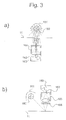
- FIG. 3 shows two embodiments of the sensor.
- the sensor consists of Radiation source and detector, advantageous is the use of a spectral Bandpass filter, which operates in the wavelength range from 2.8 microns to 3 microns.
- FIG. 3 a shows a transmission measurement.
- the detector includes a radiation sensitive surface 162, the e.g. consists of a PbS or PbSe semiconductor.
- the detector contains furthermore, an electronic amplifier circuit 163.
- the sensor has an aperture 164. This ensures that only on a limited part of the track scattered light is detected.
- FIG. 3b shows a reflection arrangement.
- the recognizes Detector the radiation reflected from the web.
- the imaging lens 165 For the limitation of Measurement on a small area uses an imaging lens 165.
- Spectral filter 166 is located in the radiation path in front of the detector.
- the two versions are only examples.
- the radiation of the source can be bundled to a smaller spot, instead of limiting the field of view through apertures and lenses.
- one Spectral filter also used in the illumination path as in the detection path become.
- Figure 4 shows diagrams showing the water content in the paper and the resulting principally illustrate the resulting signals of the sensor.
- Figure 4a represents the local water distribution, as they are after the printing unit is present.
- the absolute values for the water content depend essentially on the number of printing units and the setting of the dampening. One recognizes one Minimum of water content at the points where there is a channel strip.
- FIG. 4b shows the ideal signal curve which a sensor supplies, which is the sensor monitored moving web.
- a sensor When absorbing electromagnetic radiation applies in the present case approximately a logarithmic relationship between incident and reflected or transmitted radiation.
- the used photosensitive sensors have an approximately linear Measurement behavior on.
- the signals of the sensor can be specified in decibels become.
- the signal attenuation by absorption of the IR radiation is a measure of the amount of water in the paper.
- FIG. 4c shows a detail from the signal curve of FIG. 4b.
- the ones in the paper Amounts of water have a small lateral compared to the channel width Diffusion. You could get a high-resolution distribution if you had one fast sensor with correspondingly small measuring field used. In practice However, there is always a smoothing of the measured values, which from the time delay of the sensor reaction and the measuring surface results.
- Comparison of the measured value with a threshold value gives a digital signal, which can be evaluated for a cutting bearing control. It is advantageous to perform an automatic adjustment of the threshold value in such a way that this is set to a value at which the ratio between Detection time and non-detection time the ratio of channel strip width and sentence mirror length corresponds.
Landscapes
- Engineering & Computer Science (AREA)
- Mechanical Engineering (AREA)
- Inking, Control Or Cleaning Of Printing Machines (AREA)
- Investigating Or Analysing Materials By Optical Means (AREA)
- Controlling Sheets Or Webs (AREA)
Priority Applications (1)
| Application Number | Priority Date | Filing Date | Title |
|---|---|---|---|
| EP02405734A EP1287988A3 (fr) | 2001-08-31 | 2002-08-29 | Procédé et dispositif de détection de la position d'une bande de papier |
Applications Claiming Priority (5)
| Application Number | Priority Date | Filing Date | Title |
|---|---|---|---|
| DE10142636 | 2001-08-31 | ||
| DE10142636A DE10142636B4 (de) | 2001-08-31 | 2001-08-31 | Verfahren und Vorrichtung zur Detektion einer Position einer bewegten Bedruckstoffbahn |
| EP02405599 | 2002-07-12 | ||
| EP02405599 | 2002-07-12 | ||
| EP02405734A EP1287988A3 (fr) | 2001-08-31 | 2002-08-29 | Procédé et dispositif de détection de la position d'une bande de papier |
Publications (2)
| Publication Number | Publication Date |
|---|---|
| EP1287988A2 true EP1287988A2 (fr) | 2003-03-05 |
| EP1287988A3 EP1287988A3 (fr) | 2007-11-21 |
Family
ID=27214583
Family Applications (1)
| Application Number | Title | Priority Date | Filing Date |
|---|---|---|---|
| EP02405734A Withdrawn EP1287988A3 (fr) | 2001-08-31 | 2002-08-29 | Procédé et dispositif de détection de la position d'une bande de papier |
Country Status (1)
| Country | Link |
|---|---|
| EP (1) | EP1287988A3 (fr) |
Cited By (2)
| Publication number | Priority date | Publication date | Assignee | Title |
|---|---|---|---|---|
| DE102007003488A1 (de) * | 2007-01-24 | 2008-07-31 | Man Roland Druckmaschinen Ag | Verfahren zur Schnittregisterregelung |
| CN103587226A (zh) * | 2013-11-01 | 2014-02-19 | 深圳报业集团印务有限公司 | 印报机自动上下纸卷系统 |
Citations (1)
| Publication number | Priority date | Publication date | Assignee | Title |
|---|---|---|---|---|
| DE19910835C1 (de) | 1999-03-11 | 2000-09-07 | Innomess Elektronik Gmbh | Verfahren zur Regelung einer Schnittposition an einer bedruckten Bahn für eine Rollenrotationsdruckmaschine |
Family Cites Families (1)
| Publication number | Priority date | Publication date | Assignee | Title |
|---|---|---|---|---|
| US4733078A (en) * | 1986-08-25 | 1988-03-22 | Accuray Corporation | Measurement of moisture-stratified sheet material |
-
2002
- 2002-08-29 EP EP02405734A patent/EP1287988A3/fr not_active Withdrawn
Patent Citations (1)
| Publication number | Priority date | Publication date | Assignee | Title |
|---|---|---|---|---|
| DE19910835C1 (de) | 1999-03-11 | 2000-09-07 | Innomess Elektronik Gmbh | Verfahren zur Regelung einer Schnittposition an einer bedruckten Bahn für eine Rollenrotationsdruckmaschine |
Cited By (3)
| Publication number | Priority date | Publication date | Assignee | Title |
|---|---|---|---|---|
| DE102007003488A1 (de) * | 2007-01-24 | 2008-07-31 | Man Roland Druckmaschinen Ag | Verfahren zur Schnittregisterregelung |
| US8096241B2 (en) | 2007-01-24 | 2012-01-17 | Manroland Ag | Method for cut-off register control |
| CN103587226A (zh) * | 2013-11-01 | 2014-02-19 | 深圳报业集团印务有限公司 | 印报机自动上下纸卷系统 |
Also Published As
| Publication number | Publication date |
|---|---|
| EP1287988A3 (fr) | 2007-11-21 |
Similar Documents
| Publication | Publication Date | Title |
|---|---|---|
| EP2566695B1 (fr) | Procede de reglage et dispositif pour determiner la distance optimale entre au moins deux cylindres impliques dans le procede d'impression | |
| DE69307322T2 (de) | Vorrichtung zur erfassung von fehlern in fasermaterialien | |
| EP2943340B1 (fr) | Procédé permettant de fabriquer une bande de papier sans fin | |
| EP0314892B1 (fr) | Bloc détecteur | |
| EP0811146B1 (fr) | Procede permettant de mesurer la position du bord de bandes ou de feuilles | |
| DE69719784T2 (de) | Vorrichtung und verfahren zur markierung von defekten | |
| EP2380741A1 (fr) | Procédé et dispositif de mesure de l'épaisseur d'une couche d'agent mouillant ou d'émulsion d'encre dans un procédé d'impression offset | |
| DE3148076A1 (de) | Anordnung zum messen und steuern der farbdichte eines drucks | |
| EP0744289B1 (fr) | Procédé de régulation de la quantité d'humidité | |
| DE3800877A1 (de) | Verfahren zum messen von dublierverschiebungen | |
| DE10142636B4 (de) | Verfahren und Vorrichtung zur Detektion einer Position einer bewegten Bedruckstoffbahn | |
| DE2735943C2 (de) | Vorrichtung zur Überprüfung der Druckgüte von mehrfarbig bedruckten, in einem Stapel abgelegten Bogen | |
| EP2155492A2 (fr) | Procédé, système et presse rotative permettant la surveillance de l'image d'impression | |
| DE4237004A1 (de) | Verfahren zur Online-Farbregelung von Druckmaschinen | |
| DE3113674A1 (de) | Vorrichtung zum messen der feuchtmittelmenge auf der druckplatte einer offset-druckmaschine | |
| EP1279919A1 (fr) | Appareil pour détécter la position du bord d'un produit | |
| EP1287988A2 (fr) | Procédé et dispositif de détection de la position d'une bande de papier | |
| EP2523809A1 (fr) | Procédé et dispositif destinés à optimiser la position relative d'au moins deux cylindres d'impression | |
| DE3314333A1 (de) | Verfahren und vorrichtung zur regelung der farbzufuhr zu den farbwerken einer mehrfarbendruckmaschine | |
| EP0860276A1 (fr) | Procédé et dispositif de contrÔle de qualité | |
| EP0513009B1 (fr) | Agencement pour le positionnement lateral d'un support d'enregistrement dans un appareil a imprimer ou a copier | |
| DE69113957T2 (de) | Verfahren und Vorrichtung zur Regelung des Feucht- und Farbgleichgewichts auf einer Druckplatte einer Offsetmaschine. | |
| DE1918064A1 (de) | Folie oder Bahn mit Markierungspunkten | |
| DE3220093A1 (de) | Einrichtung zur farbdichtemessung an laufenden, bahnfoermigen druckmaterialien | |
| DE10251610A1 (de) | Verfahren und Vorrichtung zur optischen Porositätsmessung und Positionsbestimmung von Perforation mit einem Dual-Sensorsystem |
Legal Events
| Date | Code | Title | Description |
|---|---|---|---|
| PUAI | Public reference made under article 153(3) epc to a published international application that has entered the european phase |
Free format text: ORIGINAL CODE: 0009012 |
|
| AK | Designated contracting states |
Kind code of ref document: A2 Designated state(s): AT BE BG CH CY CZ DE DK EE ES FI FR GB GR IE IT LI LU MC NL PT SE SK TR Designated state(s): AT BE BG CH CY CZ DE DK EE ES FI FR GB GR IE IT LI LU MC NL PT SE SK TR |
|
| AX | Request for extension of the european patent |
Extension state: AL LT LV MK RO SI |
|
| RAP1 | Party data changed (applicant data changed or rights of an application transferred) |
Owner name: WIFAG MASCHINENFABRIK AG |
|
| PUAL | Search report despatched |
Free format text: ORIGINAL CODE: 0009013 |
|
| AK | Designated contracting states |
Kind code of ref document: A3 Designated state(s): AT BE BG CH CY CZ DE DK EE ES FI FR GB GR IE IT LI LU MC NL PT SE SK TR |
|
| AX | Request for extension of the european patent |
Extension state: AL LT LV MK RO SI |
|
| RIC1 | Information provided on ipc code assigned before grant |
Ipc: B65H 23/00 20060101ALI20071018BHEP Ipc: B41F 33/00 20060101ALI20071018BHEP Ipc: B41F 13/02 20060101AFI20030107BHEP |
|
| 17P | Request for examination filed |
Effective date: 20080507 |
|
| 17Q | First examination report despatched |
Effective date: 20080613 |
|
| AKX | Designation fees paid |
Designated state(s): AT BE BG CH CY CZ DE DK EE ES FI FR GB GR IE IT LI LU MC NL PT SE SK TR |
|
| GRAP | Despatch of communication of intention to grant a patent |
Free format text: ORIGINAL CODE: EPIDOSNIGR1 |
|
| GRAS | Grant fee paid |
Free format text: ORIGINAL CODE: EPIDOSNIGR3 |
|
| STAA | Information on the status of an ep patent application or granted ep patent |
Free format text: STATUS: THE APPLICATION IS DEEMED TO BE WITHDRAWN |
|
| 18D | Application deemed to be withdrawn |
Effective date: 20110621 |