EP1288098A1 - Radsensor - Google Patents
Radsensor Download PDFInfo
- Publication number
- EP1288098A1 EP1288098A1 EP02090264A EP02090264A EP1288098A1 EP 1288098 A1 EP1288098 A1 EP 1288098A1 EP 02090264 A EP02090264 A EP 02090264A EP 02090264 A EP02090264 A EP 02090264A EP 1288098 A1 EP1288098 A1 EP 1288098A1
- Authority
- EP
- European Patent Office
- Prior art keywords
- coils
- coil
- track
- wheel
- wheel sensor
- Prior art date
- Legal status (The legal status is an assumption and is not a legal conclusion. Google has not performed a legal analysis and makes no representation as to the accuracy of the status listed.)
- Granted
Links
- XEEYBQQBJWHFJM-UHFFFAOYSA-N Iron Chemical compound [Fe] XEEYBQQBJWHFJM-UHFFFAOYSA-N 0.000 claims abstract description 14
- 238000004804 winding Methods 0.000 claims abstract description 14
- 238000001514 detection method Methods 0.000 claims abstract description 10
- 230000001939 inductive effect Effects 0.000 claims abstract description 10
- 229910052742 iron Inorganic materials 0.000 claims abstract description 7
- 230000002452 interceptive effect Effects 0.000 claims abstract 2
- 230000001419 dependent effect Effects 0.000 claims 3
- 239000004020 conductor Substances 0.000 claims 1
- 230000000694 effects Effects 0.000 abstract description 9
- 241000881711 Acipenser sturio Species 0.000 abstract description 2
- 230000006698 induction Effects 0.000 description 6
- 230000035945 sensitivity Effects 0.000 description 4
- 230000004907 flux Effects 0.000 description 3
- 230000009977 dual effect Effects 0.000 description 2
- 230000004048 modification Effects 0.000 description 2
- 238000012986 modification Methods 0.000 description 2
- 230000000149 penetrating effect Effects 0.000 description 2
- 230000009467 reduction Effects 0.000 description 2
- 230000008901 benefit Effects 0.000 description 1
- 239000003990 capacitor Substances 0.000 description 1
- 230000001447 compensatory effect Effects 0.000 description 1
- 230000005281 excited state Effects 0.000 description 1
- 230000002045 lasting effect Effects 0.000 description 1
- 238000005457 optimization Methods 0.000 description 1
- 230000035699 permeability Effects 0.000 description 1
- 230000004044 response Effects 0.000 description 1
- 238000005096 rolling process Methods 0.000 description 1
- 230000001953 sensory effect Effects 0.000 description 1
- 230000011664 signaling Effects 0.000 description 1
Images


Classifications
-
- B—PERFORMING OPERATIONS; TRANSPORTING
- B61—RAILWAYS
- B61L—GUIDING RAILWAY TRAFFIC; ENSURING THE SAFETY OF RAILWAY TRAFFIC
- B61L1/00—Devices along the route controlled by interaction with the vehicle or train
- B61L1/16—Devices for counting axles; Devices for counting vehicles
- B61L1/163—Detection devices
- B61L1/165—Electrical
Definitions
- the invention relates to a wheel sensor and a wheel sensor arrangement according to the preamble of the independent claims 1, 3, 8 and 10.
- Wheel sensors are used in railway systems for the Track vacancy detection, but also for other switching and signaling tasks used. It is mainly the magnetic field influencing Effect of the iron wheels of the rail vehicles exploited.
- inductive sensors attached to the track body that generate a specific magnetic field can be Record the retroactive effect of the iron wheels, with each wheel detection a wheel impulse is registered.
- the number of wheel impulses gives in cooperation with one Another wheel sensor provides information about the occupancy of the intermediate one Track section.
- This track vacancy notification represents an essential decision criterion for control of turnouts and signals.
- Frequency selection also cannot avoid that interference fields frequency components in the range of the working frequency of the inductive sensor included. Usually lie the working frequencies in the range from 30 kHz to 1 MHz, while Interference fields can also reach frequencies up to 2 MHz can.
- Another approach is based on compensation efforts the way that the interference magnetic field by building an opposing Field is virtually neutralized.
- the DE-A1-197 09 844 is a coil arrangement with a magnetic Core provided. Two concentrically arranged Coils are switched so that when shared Magnetic fields flow in opposite directions. A magnetic one In contrast, interference field induces interference voltages in both coils, because of the opposite connection of the two Compensate coils.
- the coil assembly is part of one Get inductive sensor for generating a working magnetic field remains. The iron mass of a wheel running over changes the properties of the working magnetic field, what is sensory is recorded.
- Problematic with this approach is, however, that a very strong interference magnetic field, for example that of an excited eddy current brake, the coil core like that can magnetize that an unwanted response of the Sensor is caused.
- a similar but coreless coil arrangement is from the DE-A1-199 15 597 known.
- the sensitivity of this generic Axle counter is low, however, because of the detection magnetic field of the wheel created the area of the flange of the wheel does not penetrate optimally. Besides, can Wetness on the sensor housing at the usually high working frequencies coreless coil arrangements for a further reduction sensor sensitivity.
- the object of the invention is to overcome these disadvantages eliminate and specify a wheel sensor with inductive sensor, its parameters in terms of sensitivity and thus with regard to the reliability of the overall system are optimized.
- the second coil is preferably centric according to claim 2 arranged within the first coil.
- the compensation effect is however also present when the inner coil is arranged eccentrically.
- the coil shapes can also be very be different.
- the inner coil have circular turns and eccentric within an oval outer coil.
- Claim 3 characterizes a further solution to the problem, where compared to the solution according to claim 1 additionally simplification is achieved. Coils of different Geometry and different numbers of turns are included this alternative solution is not required. Instead it is an overlapping arrangement in the vertical projection similar coils are provided, the winding planes are virtually arranged one above the other. Because the coils are not in each other or are arranged penetrating the magnetic field generated by one coil closes the other coil equal parts with opposite inner and outer magnetic fluxes, that is, the coils are magnetic decoupled from each other.
- the coils are preferably very flat, spiral wound disc coils. To this The coils can be easily inserted into the housing Install the wheel sensor.
- the winding planes of the coils both alternative solutions run parallel to the track level.
- both Coils with the same angle of inclination to a horizontal surface tilted in the direction of the track. Magnetic interference fields then pass through both coils with the same intensity and Direction and cancel each other out even if the field is not runs parallel to the coil longitudinal axes.
- two wheel sensors are arranged one behind the other. On this can be done based on the time interval between the Wheel pulse registration the direction of travel of one of the two Determine the wheel sensors of a rolling rail vehicle.
- Claim 10 characterizes a dual wheel sensor arrangement, in which there are also the adjacent coils of the two wheel sensors overlap.
- the magnetic one also works in this area Decoupling according to claim 3.
- the advantage of this arrangement is that the geometric overlap of the Wheel sensors have a longer overlap phase of one wheel has influence exerted on both sensors.
- FIG. 1 schematically illustrates the operation of an inductive sensor with interference field compensation according to the prior art.
- the sensor essentially consists of an oscillator 1 and an oscillating circuit 2 with a capacitor C and two coils L1 and L2.
- the interference voltages U StörL1 and U StörL2 of an interference magnetic field ⁇ s acting in the same way on both coils L1 and L2 (FIG. 2 and FIG. 5).
- the two coils L1 and L2 in the LC resonant circuit 2 are connected in such a way that the interference voltages U StörL1 and U StörL2 are opposed at the same absolute value and thus cancel each other out.
- a working voltage U oszL1 or U oszL2 applied by the oscillator 1 to the LC oscillating circuit 2 for generating a working magnetic field is hardly influenced by this arrangement.
- Figure 2 shows a track body 3 in perspective view with a first embodiment of a coil arrangement according to the invention for interference magnetic field compensation. It is seen that a noise magnetic field ⁇ s of a rail current I s is generated.
- the two coils L1 and L2 connected in series are designed as the inner coil Li and the outer coil La, the winding orientations of the two coils Li and La being opposed to one another, as shown in FIGS. 3a and 4 Arrows symbolize point.
- the number of turns n Li of the inner coil Li is greater than the number of turns n La of the outer coil La.
- the compensation effect is also present if, as in Figure 4, the inner coil Li is not centered in the outer Coil La is arranged.
- the Coils Li and La almost any shape, such as circular, have square, rectangular or oval.
- Figures 5 to 10 relate to another invention Embodiment of an interference field compensating Coil assembly. Compared to that shown in Figures 2 to 4 Variant differs from this embodiment in particular in that the coils used L1 and L2 in contrast to the coils Li and La of the same geometry exhibit. This results in a reduction in effort or the cost.
- Figure 5 shows in an analogous representation to Figure 2 that two mutually offset and partially overlapping coils L1 and L2 of the same geometry and number of turns are provided. Since both coils L1 and L2 are identical, the same disturbing voltage U and U StörL1 StörL2 induces the disturbance magnetic field ⁇ s in both coils L1 and L2 ( Figure 1). For compensation, the coils L1 and L2 are connected to one another, as explained for FIG. 1.
- Each coil L1 and L2 generates a magnetic field like an individual coil, since there is no mutual interference due to the magnetic decoupling. It therefore has no influence that the magnetic fields B L1 and B L2 of both coils L1 and L2 are opposite in the oscillator mode. Both coils L1 and L2 contribute equally to the detection of a wheel because their magnetic fields B L1 and B L2 are influenced in the same way by the flange 4 (FIG. 8) of a wheel. Compared to an arrangement with only one sensor coil, that is to say without including this individual coil in a coil majority for interference field compensation, the effective range of the wheel is extended approximately by the lateral offset X of the two coils L1 and L2.
- Figure 8 shows the coils L1_1, L2_1 and L2_2 of two wheel sensors relative to the track body 3.
- the coils are L1_1, L2_1 as well as L2_2 and L1_2 in this way, for example within one Sensor housing, attached that their centers are constant Height to the horizontal base of the track body 3 have, the winding planes inclined to the track level are.
- Magnetic interference fields then penetrate the two coils L1_1 and L2_1 or L2_2 and L1_2 each with the same intensity and direction and cancel each other out, even if that Interference field does not run parallel to the coil longitudinal axes.
- the double sensor shown in Figure 8 is from the wheel flange 4 of the wheel in a certain chronological order run over so that from the signal order to the direction of travel of the rail vehicle can be closed.
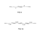
- FIG. 9 shows a preferred coil shape for wheel sensors shown.
- the coils L1 and L2 are disc-shaped and wrapped in spirals.
- the height of the disc coils corresponds to the diameter of the winding wire and is consequently so small that the two overlapping coils L1 and L2 built into the housing of a wheel sensor without inclination can be.
- Figure 10 illustrates a double sensor with disc coils L1_Sys1 and L2_Sys1 as well as L1_Sys1 and L2_Sys2, where also the adjacent coils L2_Sys1 and L1_Sys2 of the two Sensor systems Sys1 and Sys2 overlap
Landscapes
- Engineering & Computer Science (AREA)
- Automation & Control Theory (AREA)
- Mechanical Engineering (AREA)
- Train Traffic Observation, Control, And Security (AREA)
- Investigating Or Analyzing Materials By The Use Of Magnetic Means (AREA)
- Arrangements For Transmission Of Measured Signals (AREA)
- Measuring Fluid Pressure (AREA)
- Transmission And Conversion Of Sensor Element Output (AREA)
- Electric Propulsion And Braking For Vehicles (AREA)
- Pinball Game Machines (AREA)
- Vehicle Body Suspensions (AREA)
Abstract
Description
- Figur 1
- eine schematische Darstellung des Kompensationsprinzips, wie sie aus dem Stand der Technik bekannt ist,
- Figur 2
- eine erste erfindungsgemäße Ausführungsform einer Spulenanordnung,
- Figur 3a
- eine Seitenansicht und eine Draufsicht einer Spulenanordnung gemäß Figur 2 mit Arbeitsfeldbeaufschlagung,
- Figur 3b
- die Seitenansicht gemäß Figur 3a mit Störfeldbeaufschlagung,
- Figur 4
- eine Abwandlung der ersten Ausführungsform in Seitenansicht und in Draufsicht,
- Figur 5
- eine zweite erfindungsgemäße Ausführungsform einer Spulenanordnung,
- Figur 6
- eine Seitenansicht und eine Draufsicht der zweiten Ausführungsform gemäß Figur 5,
- Figur 7a
- eine Seitenansicht gemäß Figur 6 mit Arbeitsfeldbeaufschlagung,
- Figur 7b
- eine Seitenansicht gemäß Figur 6 mit Störfeldbeaufschlagung,
- Figur 8
- eine Doppelradsensoranordnung,
- Figur 9
- eine Spulenanordnung und
- Figur 10
- eine weitere Doppelradsenoranordnung.
ULi = ULa ergibt sich für die Dimensionierung der Spulen:
bedeuten. Die innere Spule Li hat also eine dem Flächenverhältnis entsprechende höhere Windungszahl nLi als die äußere Spule La. Dieser Umstand hat zur Folge, dass die durch den Schwingkreisstrom des Oszillators 1 in beiden Spulen Li und La entgegengesetzt auftretenden Induktionen BLi und BLa nicht gleich groß sind und im Bereich der inneren Spule Li gemäß Figur 3a eine ausreichend hohe Gesamtinduktion BLi-BLa zur Detektion eines den induktiven Sensor überfahrenden Rades eines Schienenfahrzeuges verbleibt. Dagegen kompensieren sich der innere und der äußere Anteil eines Störmagnetfeldes mit der Gesamtinduktion BStör gegenseitig, wie Figur 3b in symbolhafter Darstellung zeigt.
Claims (10)
- Radsensor, insbesondere für eine Gleisfreimeldeanlage, mit mindestens einem gleisseitigen induktiven Sensor zur Erfassung einer Magnetfeldänderung infolge das Gleis überfahrender Eisenräder eines Schienenfahrzeuges und einer kernlose Spulen (L1, L2; La, Li) aufweisenden Anordnung zur Kompensation störender Magnetfelder (s, BStör),
dadurch gekennzeichnet, dass
eine erste kernlose Spule (La) und eine innerhalb dieser angeordnete, bei gemeinsamer Beströmung ein gegensinniges Magnetfeld (BLi) erzeugende zweite kernlose Spule (Li) vorgesehen sind, wobei die Windungsebenen der Spulen (La, Li) im Wesentlichen übereinstimmen und die Windungszahlen (nLi und nLa) der Spulen (Li und La) umgekehrt proportional zu den Spulenflächen (ALa und ALi) sind. - Radsensor nach Anspruch 1,
dadurch gekennzeichnet, dass
die zweite Spule (Li) zentrisch innerhalb der ersten Spule (La) angeordnet ist. - Radsensor, insbesondere für eine Gleisfreimeldeanlage, mit mindestens einem gleisseitigen induktiven Sensor zur Erfassung einer Magnetfeldänderung infolge das Gleis überfahrender Eisenräder eines Schienenfahrzeuges und einer kernlose Spulen (L1, L2) aufweisenden Anordnung zur Kompensation störender Magnetfelder (s, BStör),
dadurch gekennzeichnet, dass
zwei kernlose Spulen (L1, L2) mit im Wesentlichen gleicher Geometrie und gleicher Windungszahlen vorgesehen sind, deren Windungsebenen zueinander im Wesentlichen parallel verlaufen, wobei sich die Spulen (L1, L2) in Vertikalprojektion überlappen und bei gemeinsamer Beströmung gegensinnige Magnetfelder erzeugen. - Radsensor nach einem der vorhergehenden Ansprüche,
dadurch gekennzeichnet, dass die Spulen (L1, L2; L1Sys1, L2Sys1, L1_Sys2, L2_Sys2) als Scheibenspulen, deren Höhe dem Durchmesser des verwendeten Leiters entspricht, ausgebildet sind. - Radsensor nach einem der vorhergehenden Ansprüche,
dadurch gekennzeichnet, dass
die Windungsebenen der Spulen (L1, L2; La, Li) im Wesentlichen parallel zur Gleisebene verlaufen. - Radsensor nach Anspruch 3,
dadurch gekennzeichnet, dass
die Windungsebenen der Spulen (L1_1, L2_1; L2_2, L2_1) zur Gleisebene eine im Wesentlichen in Gleislängsrichtung orientierte Neigung aufweisen und die Verbindungslinie der Spulenmittelpunkte auf einer horizontalen Ebene gleisparallel verläuft. - Radsensor nach einem der vorangehenden Ansprüche,
dadurch gekennzeichnet, dass
die Spulen (L1, L2; Li, La) runde, insbesondere kreisförmige und/oder ovale Windungen aufweisen. - Fahrtrichtungsabhängige Radsensorenanordnung, gekennzeichnet durch
die paarweise Verwendung von in Gleisrichtung beabstandeten Radsensoren nach einem der vorangehenden Ansprüche. - Fahrtrichtungsabhängige Radsensorenanordnung nach Anspruch 8, gekennzeichnet durch
die Verwendung von Radsensoren nach Anspruch 5, wobei die Windungsebenen der Spulenpaare (L1_1 und L2_1; L2_2 und L1_2) dachförmig in entgegengesetzte Richtungen orientierte Neigungen aufweisen. - Fahrrichtungsabhängige Radsensoranordnung, gekennzeichnet durch
die paarweise Verwendung von in Gleisrichtung sich überlappenden Radsensoren nach einem der vorangehenden Ansprüche.
Applications Claiming Priority (2)
| Application Number | Priority Date | Filing Date | Title |
|---|---|---|---|
| DE10137519 | 2001-07-30 | ||
| DE10137519A DE10137519A1 (de) | 2001-07-30 | 2001-07-30 | Radsensor |
Publications (2)
| Publication Number | Publication Date |
|---|---|
| EP1288098A1 true EP1288098A1 (de) | 2003-03-05 |
| EP1288098B1 EP1288098B1 (de) | 2008-12-31 |
Family
ID=7693880
Family Applications (1)
| Application Number | Title | Priority Date | Filing Date |
|---|---|---|---|
| EP02090264A Expired - Lifetime EP1288098B1 (de) | 2001-07-30 | 2002-07-17 | Radsensor und Anordnung |
Country Status (6)
| Country | Link |
|---|---|
| EP (1) | EP1288098B1 (de) |
| AT (1) | ATE419158T1 (de) |
| DE (2) | DE10137519A1 (de) |
| DK (1) | DK1288098T3 (de) |
| ES (1) | ES2316521T3 (de) |
| PT (1) | PT1288098E (de) |
Cited By (3)
| Publication number | Priority date | Publication date | Assignee | Title |
|---|---|---|---|---|
| DE102009007068A1 (de) | 2009-01-29 | 2010-08-12 | Siemens Aktiengesellschaft | Radsensor |
| EP2305533A3 (de) * | 2004-07-16 | 2012-04-18 | Lynxrail Corporation | Vorrichtung zum Erkennen des Gierens und des Angriffwinkels des Radsatzes eines Schienenfahrzeuges |
| EP3569466A1 (de) * | 2018-05-14 | 2019-11-20 | Pintsch GmbH | Sensor zum erfassen von metallteilen, sowie verfahren zum abschwächen eines magnetischen feldes |
Families Citing this family (9)
| Publication number | Priority date | Publication date | Assignee | Title |
|---|---|---|---|---|
| DE102005023726B4 (de) * | 2005-05-23 | 2007-11-22 | Frauscher Gmbh | Verfahren und Vorrichtung zur Vermeidung von ungewollten Beeinflussungen von Doppelsensoren |
| DE102007023475B4 (de) | 2007-05-15 | 2009-07-09 | Siemens Ag | Radsensor |
| DE102007023476B4 (de) | 2007-05-15 | 2009-07-09 | Siemens Ag | Radsensor |
| DE102008056481A1 (de) | 2008-11-05 | 2010-05-06 | Siemens Aktiengesellschaft | Radsensor |
| DE102009053257B4 (de) * | 2009-11-05 | 2013-10-02 | Siemens Aktiengesellschaft | Radsensor |
| DE102012212939A1 (de) | 2012-07-24 | 2014-01-30 | Siemens Aktiengesellschaft | Radsensor |
| DE102017220281A1 (de) | 2017-11-14 | 2019-05-16 | Siemens Aktiengesellschaft | Sensoreinrichtung |
| DE102018111448A1 (de) | 2018-05-14 | 2019-11-14 | PINTSCH TIEFENBACH GmbH | Sensor zum Erfassen von Metallteilen, sowie Verfahren zum Abschwächen eines magnetischen Feldes |
| DE102021212809A1 (de) | 2021-11-15 | 2023-05-17 | Siemens Mobility GmbH | Sensoreinrichtung und Verfahren zum Erfassen einer Magnetfeldänderung |
Citations (4)
| Publication number | Priority date | Publication date | Assignee | Title |
|---|---|---|---|---|
| US3882374A (en) * | 1974-04-18 | 1975-05-06 | Us Army | Transmitting-receiving coil configuration |
| DD261004A1 (de) * | 1987-06-25 | 1988-10-12 | Deutsche Reichsbahn | Magnetostatischer impulsgeber |
| DE19709844A1 (de) * | 1997-02-28 | 1998-09-03 | Siemens Ag | Sensor, insbesondere Radsensor |
| DE19915597A1 (de) * | 1998-04-08 | 1999-12-30 | Josef Frauscher | Radsensor |
Family Cites Families (1)
| Publication number | Priority date | Publication date | Assignee | Title |
|---|---|---|---|---|
| DE3842882A1 (de) * | 1988-12-20 | 1990-06-21 | Knorr Bremse Ag | Verfahren und anordnung zur unterdrueckung des stoereinflusses magnetischer bremsen auf magnetische achszaehler |
-
2001
- 2001-07-30 DE DE10137519A patent/DE10137519A1/de not_active Ceased
-
2002
- 2002-07-17 DK DK02090264T patent/DK1288098T3/da active
- 2002-07-17 EP EP02090264A patent/EP1288098B1/de not_active Expired - Lifetime
- 2002-07-17 PT PT02090264T patent/PT1288098E/pt unknown
- 2002-07-17 ES ES02090264T patent/ES2316521T3/es not_active Expired - Lifetime
- 2002-07-17 DE DE50213159T patent/DE50213159D1/de not_active Expired - Lifetime
- 2002-07-17 AT AT02090264T patent/ATE419158T1/de active
Patent Citations (4)
| Publication number | Priority date | Publication date | Assignee | Title |
|---|---|---|---|---|
| US3882374A (en) * | 1974-04-18 | 1975-05-06 | Us Army | Transmitting-receiving coil configuration |
| DD261004A1 (de) * | 1987-06-25 | 1988-10-12 | Deutsche Reichsbahn | Magnetostatischer impulsgeber |
| DE19709844A1 (de) * | 1997-02-28 | 1998-09-03 | Siemens Ag | Sensor, insbesondere Radsensor |
| DE19915597A1 (de) * | 1998-04-08 | 1999-12-30 | Josef Frauscher | Radsensor |
Cited By (3)
| Publication number | Priority date | Publication date | Assignee | Title |
|---|---|---|---|---|
| EP2305533A3 (de) * | 2004-07-16 | 2012-04-18 | Lynxrail Corporation | Vorrichtung zum Erkennen des Gierens und des Angriffwinkels des Radsatzes eines Schienenfahrzeuges |
| DE102009007068A1 (de) | 2009-01-29 | 2010-08-12 | Siemens Aktiengesellschaft | Radsensor |
| EP3569466A1 (de) * | 2018-05-14 | 2019-11-20 | Pintsch GmbH | Sensor zum erfassen von metallteilen, sowie verfahren zum abschwächen eines magnetischen feldes |
Also Published As
| Publication number | Publication date |
|---|---|
| DE10137519A1 (de) | 2003-02-13 |
| PT1288098E (pt) | 2009-02-02 |
| DE50213159D1 (de) | 2009-02-12 |
| EP1288098B1 (de) | 2008-12-31 |
| ATE419158T1 (de) | 2009-01-15 |
| ES2316521T3 (es) | 2009-04-16 |
| DK1288098T3 (da) | 2009-04-20 |
Similar Documents
| Publication | Publication Date | Title |
|---|---|---|
| DE69717188T2 (de) | Mit Magnetfeldveränderungen arbeitender Bewegungs- und Positionsdetektor | |
| EP0900997B1 (de) | Induktiver Winkelsensor | |
| EP0901002B1 (de) | Induktiver Winkelsensor für ein Kraftfahrzeug | |
| EP1288098B1 (de) | Radsensor und Anordnung | |
| DE60130700T2 (de) | Induktiver Positionsgeber | |
| EP2349810B1 (de) | Radsensor | |
| EP2496459B1 (de) | Radsensor | |
| WO2012004251A1 (de) | Induktive sensoreinrichtung sowie induktiver näherungssensor mit einer induktiven sensoreinrichtung | |
| EP3107791B1 (de) | Sensoreinrichtung zum erfassen einer magnetfeldänderung sowie anlage des spurgebundenen verkehrs mit zumindest einer solchen sensoreinrichtung | |
| AT406139B (de) | Radsensor | |
| DE102012212939A1 (de) | Radsensor | |
| EP0340660B1 (de) | Einrichtung an Gleiswegen zur Erzeugung von Anwesenheitskriterien von schienengebundenen Rädern | |
| DE10221577B3 (de) | Magnetischer Radsensor | |
| DE102007023476B4 (de) | Radsensor | |
| DE2335280C2 (de) | Fahrzeugbetätigte Einrichtung | |
| EP3569466B1 (de) | Sensor zum erfassen von metallteilen, sowie verfahren zum abschwächen eines magnetischen feldes | |
| DE2937650C2 (de) | Wirbelstromprüfsonde zum Abtasten der Oberfläche eines metallischen Prüfteiles | |
| EP4536500A1 (de) | Verfahren zum positionieren eines fahrzeugs | |
| EP4144612A1 (de) | Sensoreinrichtung, anordnung und verfahren zum erfassen einer änderung eines magnetfeldes | |
| EP3294608A1 (de) | Sensoreinrichtung zum detektieren eines sich entlang einer fahrschiene bewegenden rades | |
| DE2201769C3 (de) | Fahrzeugbetätigter Gleiskontakt zum Erzeugen von Anwesenheits- und/oder Richtungskriterien | |
| EP2382120B1 (de) | Radsensor | |
| DE3916730A1 (de) | Anordnung zur spurfuehrung eines fahrzeugs ueber passiven leitmitteln | |
| EP4467416A1 (de) | Induktiv wirkende radsensoranordnung | |
| AT501703A1 (de) | System zur induktiven zugsicherung |
Legal Events
| Date | Code | Title | Description |
|---|---|---|---|
| PUAI | Public reference made under article 153(3) epc to a published international application that has entered the european phase |
Free format text: ORIGINAL CODE: 0009012 |
|
| AK | Designated contracting states |
Kind code of ref document: A1 Designated state(s): AT BE BG CH CY CZ DE DK EE ES FI FR GB GR IE IT LI LU MC NL PT SE SK TR |
|
| AX | Request for extension of the european patent |
Extension state: AL LT LV MK RO SI |
|
| 17P | Request for examination filed |
Effective date: 20030317 |
|
| AKX | Designation fees paid |
Designated state(s): AT BE BG CH CY CZ DE DK EE ES FI FR GB GR IE IT LI LU MC NL PT SE SK TR |
|
| REG | Reference to a national code |
Ref country code: SE Ref legal event code: TRGR |
|
| RTI1 | Title (correction) |
Free format text: WHEEL SENSOR AND ARRANGEMENT |
|
| GRAP | Despatch of communication of intention to grant a patent |
Free format text: ORIGINAL CODE: EPIDOSNIGR1 |
|
| GRAS | Grant fee paid |
Free format text: ORIGINAL CODE: EPIDOSNIGR3 |
|
| GRAA | (expected) grant |
Free format text: ORIGINAL CODE: 0009210 |
|
| AK | Designated contracting states |
Kind code of ref document: B1 Designated state(s): AT BE BG CH CY CZ DE DK EE ES FI FR GB GR IE IT LI LU MC NL PT SE SK TR |
|
| REG | Reference to a national code |
Ref country code: CH Ref legal event code: EP Ref country code: GB Ref legal event code: FG4D Free format text: NOT ENGLISH |
|
| REG | Reference to a national code |
Ref country code: CH Ref legal event code: NV Representative=s name: SIEMENS SCHWEIZ AG |
|
| REG | Reference to a national code |
Ref country code: PT Ref legal event code: SC4A Free format text: AVAILABILITY OF NATIONAL TRANSLATION Effective date: 20090120 |
|
| REF | Corresponds to: |
Ref document number: 50213159 Country of ref document: DE Date of ref document: 20090212 Kind code of ref document: P |
|
| REG | Reference to a national code |
Ref country code: IE Ref legal event code: FG4D Free format text: LANGUAGE OF EP DOCUMENT: GERMAN |
|
| REG | Reference to a national code |
Ref country code: GR Ref legal event code: EP Ref document number: 20090400630 Country of ref document: GR |
|
| REG | Reference to a national code |
Ref country code: ES Ref legal event code: FG2A Ref document number: 2316521 Country of ref document: ES Kind code of ref document: T3 |
|
| REG | Reference to a national code |
Ref country code: DK Ref legal event code: T3 |
|
| PG25 | Lapsed in a contracting state [announced via postgrant information from national office to epo] |
Ref country code: EE Free format text: LAPSE BECAUSE OF FAILURE TO SUBMIT A TRANSLATION OF THE DESCRIPTION OR TO PAY THE FEE WITHIN THE PRESCRIBED TIME-LIMIT Effective date: 20081231 |
|
| PG25 | Lapsed in a contracting state [announced via postgrant information from national office to epo] |
Ref country code: CZ Free format text: LAPSE BECAUSE OF FAILURE TO SUBMIT A TRANSLATION OF THE DESCRIPTION OR TO PAY THE FEE WITHIN THE PRESCRIBED TIME-LIMIT Effective date: 20081231 |
|
| PG25 | Lapsed in a contracting state [announced via postgrant information from national office to epo] |
Ref country code: SK Free format text: LAPSE BECAUSE OF FAILURE TO SUBMIT A TRANSLATION OF THE DESCRIPTION OR TO PAY THE FEE WITHIN THE PRESCRIBED TIME-LIMIT Effective date: 20081231 |
|
| PLBE | No opposition filed within time limit |
Free format text: ORIGINAL CODE: 0009261 |
|
| STAA | Information on the status of an ep patent application or granted ep patent |
Free format text: STATUS: NO OPPOSITION FILED WITHIN TIME LIMIT |
|
| PGFP | Annual fee paid to national office [announced via postgrant information from national office to epo] |
Ref country code: FI Payment date: 20090709 Year of fee payment: 8 |
|
| 26N | No opposition filed |
Effective date: 20091001 |
|
| PG25 | Lapsed in a contracting state [announced via postgrant information from national office to epo] |
Ref country code: BG Free format text: LAPSE BECAUSE OF FAILURE TO SUBMIT A TRANSLATION OF THE DESCRIPTION OR TO PAY THE FEE WITHIN THE PRESCRIBED TIME-LIMIT Effective date: 20090331 |
|
| PG25 | Lapsed in a contracting state [announced via postgrant information from national office to epo] |
Ref country code: MC Free format text: LAPSE BECAUSE OF NON-PAYMENT OF DUE FEES Effective date: 20090731 |
|
| PGFP | Annual fee paid to national office [announced via postgrant information from national office to epo] |
Ref country code: BE Payment date: 20090731 Year of fee payment: 8 |
|
| REG | Reference to a national code |
Ref country code: FR Ref legal event code: ST Effective date: 20100331 |
|
| PG25 | Lapsed in a contracting state [announced via postgrant information from national office to epo] |
Ref country code: FR Free format text: LAPSE BECAUSE OF NON-PAYMENT OF DUE FEES Effective date: 20090731 |
|
| PGFP | Annual fee paid to national office [announced via postgrant information from national office to epo] |
Ref country code: GR Payment date: 20090713 Year of fee payment: 8 |
|
| BERE | Be: lapsed |
Owner name: SIEMENS A.G. Effective date: 20100731 |
|
| PG25 | Lapsed in a contracting state [announced via postgrant information from national office to epo] |
Ref country code: LU Free format text: LAPSE BECAUSE OF NON-PAYMENT OF DUE FEES Effective date: 20090717 |
|
| PG25 | Lapsed in a contracting state [announced via postgrant information from national office to epo] |
Ref country code: FI Free format text: LAPSE BECAUSE OF NON-PAYMENT OF DUE FEES Effective date: 20100717 |
|
| PG25 | Lapsed in a contracting state [announced via postgrant information from national office to epo] |
Ref country code: GR Free format text: LAPSE BECAUSE OF NON-PAYMENT OF DUE FEES Effective date: 20110202 Ref country code: BE Free format text: LAPSE BECAUSE OF NON-PAYMENT OF DUE FEES Effective date: 20100731 |
|
| PG25 | Lapsed in a contracting state [announced via postgrant information from national office to epo] |
Ref country code: TR Free format text: LAPSE BECAUSE OF FAILURE TO SUBMIT A TRANSLATION OF THE DESCRIPTION OR TO PAY THE FEE WITHIN THE PRESCRIBED TIME-LIMIT Effective date: 20081231 |
|
| PG25 | Lapsed in a contracting state [announced via postgrant information from national office to epo] |
Ref country code: CY Free format text: LAPSE BECAUSE OF FAILURE TO SUBMIT A TRANSLATION OF THE DESCRIPTION OR TO PAY THE FEE WITHIN THE PRESCRIBED TIME-LIMIT Effective date: 20081231 |
|
| PGFP | Annual fee paid to national office [announced via postgrant information from national office to epo] |
Ref country code: IE Payment date: 20140723 Year of fee payment: 13 |
|
| PGFP | Annual fee paid to national office [announced via postgrant information from national office to epo] |
Ref country code: PT Payment date: 20140120 Year of fee payment: 13 |
|
| PGFP | Annual fee paid to national office [announced via postgrant information from national office to epo] |
Ref country code: NL Payment date: 20150703 Year of fee payment: 14 |
|
| PGFP | Annual fee paid to national office [announced via postgrant information from national office to epo] |
Ref country code: DE Payment date: 20150918 Year of fee payment: 14 Ref country code: ES Payment date: 20150807 Year of fee payment: 14 Ref country code: GB Payment date: 20150709 Year of fee payment: 14 Ref country code: DK Payment date: 20150721 Year of fee payment: 14 |
|
| PGFP | Annual fee paid to national office [announced via postgrant information from national office to epo] |
Ref country code: AT Payment date: 20150604 Year of fee payment: 14 Ref country code: SE Payment date: 20150706 Year of fee payment: 14 |
|
| PGFP | Annual fee paid to national office [announced via postgrant information from national office to epo] |
Ref country code: IT Payment date: 20150727 Year of fee payment: 14 |
|
| REG | Reference to a national code |
Ref country code: PT Ref legal event code: MM4A Free format text: LAPSE DUE TO NON-PAYMENT OF FEES Effective date: 20160118 |
|
| PGFP | Annual fee paid to national office [announced via postgrant information from national office to epo] |
Ref country code: CH Payment date: 20151002 Year of fee payment: 14 |
|
| REG | Reference to a national code |
Ref country code: GR Ref legal event code: ML Ref document number: 20090400630 Country of ref document: GR Effective date: 20110202 |
|
| REG | Reference to a national code |
Ref country code: IE Ref legal event code: MM4A |
|
| PG25 | Lapsed in a contracting state [announced via postgrant information from national office to epo] |
Ref country code: PT Free format text: LAPSE BECAUSE OF NON-PAYMENT OF DUE FEES Effective date: 20160118 |
|
| PG25 | Lapsed in a contracting state [announced via postgrant information from national office to epo] |
Ref country code: IE Free format text: LAPSE BECAUSE OF NON-PAYMENT OF DUE FEES Effective date: 20150717 |
|
| REG | Reference to a national code |
Ref country code: DE Ref legal event code: R119 Ref document number: 50213159 Country of ref document: DE |
|
| REG | Reference to a national code |
Ref country code: DK Ref legal event code: EBP Effective date: 20170131 |
|
| REG | Reference to a national code |
Ref country code: CH Ref legal event code: PL |
|
| REG | Reference to a national code |
Ref country code: NL Ref legal event code: MM Effective date: 20160801 |
|
| REG | Reference to a national code |
Ref country code: SE Ref legal event code: EUG |
|
| REG | Reference to a national code |
Ref country code: AT Ref legal event code: MM01 Ref document number: 419158 Country of ref document: AT Kind code of ref document: T Effective date: 20160717 |
|
| GBPC | Gb: european patent ceased through non-payment of renewal fee |
Effective date: 20160717 |
|
| PG25 | Lapsed in a contracting state [announced via postgrant information from national office to epo] |
Ref country code: LI Free format text: LAPSE BECAUSE OF NON-PAYMENT OF DUE FEES Effective date: 20160731 Ref country code: DE Free format text: LAPSE BECAUSE OF NON-PAYMENT OF DUE FEES Effective date: 20170201 Ref country code: SE Free format text: LAPSE BECAUSE OF NON-PAYMENT OF DUE FEES Effective date: 20160718 Ref country code: CH Free format text: LAPSE BECAUSE OF NON-PAYMENT OF DUE FEES Effective date: 20160731 Ref country code: NL Free format text: LAPSE BECAUSE OF NON-PAYMENT OF DUE FEES Effective date: 20160801 |
|
| PG25 | Lapsed in a contracting state [announced via postgrant information from national office to epo] |
Ref country code: AT Free format text: LAPSE BECAUSE OF NON-PAYMENT OF DUE FEES Effective date: 20160717 Ref country code: GB Free format text: LAPSE BECAUSE OF NON-PAYMENT OF DUE FEES Effective date: 20160717 |
|
| PG25 | Lapsed in a contracting state [announced via postgrant information from national office to epo] |
Ref country code: IT Free format text: LAPSE BECAUSE OF NON-PAYMENT OF DUE FEES Effective date: 20160717 |
|
| PG25 | Lapsed in a contracting state [announced via postgrant information from national office to epo] |
Ref country code: DK Free format text: LAPSE BECAUSE OF NON-PAYMENT OF DUE FEES Effective date: 20160731 |
|
| PG25 | Lapsed in a contracting state [announced via postgrant information from national office to epo] |
Ref country code: ES Free format text: LAPSE BECAUSE OF NON-PAYMENT OF DUE FEES Effective date: 20160718 |
|
| REG | Reference to a national code |
Ref country code: ES Ref legal event code: FD2A Effective date: 20181128 |