EP1288405A1 - Ferrure de verrouillage pour ouvrant coulissant de porte, fenêtre ou analogue - Google Patents
Ferrure de verrouillage pour ouvrant coulissant de porte, fenêtre ou analogue Download PDFInfo
- Publication number
- EP1288405A1 EP1288405A1 EP20020020755 EP02020755A EP1288405A1 EP 1288405 A1 EP1288405 A1 EP 1288405A1 EP 20020020755 EP20020020755 EP 20020020755 EP 02020755 A EP02020755 A EP 02020755A EP 1288405 A1 EP1288405 A1 EP 1288405A1
- Authority
- EP
- European Patent Office
- Prior art keywords
- sliding assembly
- housing
- slide
- wall
- cover
- Prior art date
- Legal status (The legal status is an assumption and is not a legal conclusion. Google has not performed a legal analysis and makes no representation as to the accuracy of the status listed.)
- Granted
Links
- 230000000295 complement effect Effects 0.000 claims description 14
- 210000000078 claw Anatomy 0.000 claims description 5
- 210000002105 tongue Anatomy 0.000 claims 2
- 239000000463 material Substances 0.000 abstract description 5
- 230000000717 retained effect Effects 0.000 abstract description 2
- 238000006073 displacement reaction Methods 0.000 description 8
- 210000000056 organ Anatomy 0.000 description 6
- 230000003749 cleanliness Effects 0.000 description 5
- 230000000903 blocking effect Effects 0.000 description 3
- 230000021615 conjugation Effects 0.000 description 2
- 239000000284 extract Substances 0.000 description 2
- 230000036961 partial effect Effects 0.000 description 2
- 229910052782 aluminium Inorganic materials 0.000 description 1
- XAGFODPZIPBFFR-UHFFFAOYSA-N aluminium Chemical compound [Al] XAGFODPZIPBFFR-UHFFFAOYSA-N 0.000 description 1
- 238000012550 audit Methods 0.000 description 1
- 238000005219 brazing Methods 0.000 description 1
- 230000000694 effects Effects 0.000 description 1
- 230000005057 finger movement Effects 0.000 description 1
- 230000012010 growth Effects 0.000 description 1
- 238000007373 indentation Methods 0.000 description 1
- 238000001746 injection moulding Methods 0.000 description 1
- 238000003780 insertion Methods 0.000 description 1
- 230000037431 insertion Effects 0.000 description 1
- 229910052751 metal Inorganic materials 0.000 description 1
- 239000002184 metal Substances 0.000 description 1
- 238000012986 modification Methods 0.000 description 1
- 230000004048 modification Effects 0.000 description 1
- 238000000465 moulding Methods 0.000 description 1
- 210000002445 nipple Anatomy 0.000 description 1
- 238000004080 punching Methods 0.000 description 1
- 230000002829 reductive effect Effects 0.000 description 1
- 230000000284 resting effect Effects 0.000 description 1
- 230000002441 reversible effect Effects 0.000 description 1
- 239000007787 solid Substances 0.000 description 1
- 238000003466 welding Methods 0.000 description 1
Images



Classifications
-
- E—FIXED CONSTRUCTIONS
- E05—LOCKS; KEYS; WINDOW OR DOOR FITTINGS; SAFES
- E05B—LOCKS; ACCESSORIES THEREFOR; HANDCUFFS
- E05B63/00—Locks or fastenings with special structural characteristics
- E05B63/0065—Operating modes; Transformable to different operating modes
- E05B63/0069—Override systems, e.g. allowing opening from inside without the key, even when locked from outside
-
- E—FIXED CONSTRUCTIONS
- E05—LOCKS; KEYS; WINDOW OR DOOR FITTINGS; SAFES
- E05B—LOCKS; ACCESSORIES THEREFOR; HANDCUFFS
- E05B65/00—Locks or fastenings for special use
- E05B65/08—Locks or fastenings for special use for sliding wings
- E05B65/087—Locks or fastenings for special use for sliding wings the bolts sliding parallel to the wings
-
- Y—GENERAL TAGGING OF NEW TECHNOLOGICAL DEVELOPMENTS; GENERAL TAGGING OF CROSS-SECTIONAL TECHNOLOGIES SPANNING OVER SEVERAL SECTIONS OF THE IPC; TECHNICAL SUBJECTS COVERED BY FORMER USPC CROSS-REFERENCE ART COLLECTIONS [XRACs] AND DIGESTS
- Y10—TECHNICAL SUBJECTS COVERED BY FORMER USPC
- Y10S—TECHNICAL SUBJECTS COVERED BY FORMER USPC CROSS-REFERENCE ART COLLECTIONS [XRACs] AND DIGESTS
- Y10S292/00—Closure fasteners
- Y10S292/46—Sliding door fasteners
-
- Y—GENERAL TAGGING OF NEW TECHNOLOGICAL DEVELOPMENTS; GENERAL TAGGING OF CROSS-SECTIONAL TECHNOLOGIES SPANNING OVER SEVERAL SECTIONS OF THE IPC; TECHNICAL SUBJECTS COVERED BY FORMER USPC CROSS-REFERENCE ART COLLECTIONS [XRACs] AND DIGESTS
- Y10—TECHNICAL SUBJECTS COVERED BY FORMER USPC
- Y10T—TECHNICAL SUBJECTS COVERED BY FORMER US CLASSIFICATION
- Y10T292/00—Closure fasteners
- Y10T292/08—Bolts
- Y10T292/0911—Hooked end
- Y10T292/0945—Operating means
- Y10T292/0951—Rigid
- Y10T292/0957—Spring-arm catch
-
- Y—GENERAL TAGGING OF NEW TECHNOLOGICAL DEVELOPMENTS; GENERAL TAGGING OF CROSS-SECTIONAL TECHNOLOGIES SPANNING OVER SEVERAL SECTIONS OF THE IPC; TECHNICAL SUBJECTS COVERED BY FORMER USPC CROSS-REFERENCE ART COLLECTIONS [XRACs] AND DIGESTS
- Y10—TECHNICAL SUBJECTS COVERED BY FORMER USPC
- Y10T—TECHNICAL SUBJECTS COVERED BY FORMER US CLASSIFICATION
- Y10T292/00—Closure fasteners
- Y10T292/08—Bolts
- Y10T292/096—Sliding
- Y10T292/1014—Operating means
- Y10T292/1016—Cam
-
- Y—GENERAL TAGGING OF NEW TECHNOLOGICAL DEVELOPMENTS; GENERAL TAGGING OF CROSS-SECTIONAL TECHNOLOGIES SPANNING OVER SEVERAL SECTIONS OF THE IPC; TECHNICAL SUBJECTS COVERED BY FORMER USPC CROSS-REFERENCE ART COLLECTIONS [XRACs] AND DIGESTS
- Y10—TECHNICAL SUBJECTS COVERED BY FORMER USPC
- Y10T—TECHNICAL SUBJECTS COVERED BY FORMER US CLASSIFICATION
- Y10T70/00—Locks
- Y10T70/50—Special application
- Y10T70/5093—For closures
- Y10T70/5155—Door
- Y10T70/5173—Sliding door
Definitions
- the present invention relates to a fitting of lock for sliding door, window or the like, comprising a movable sliding assembly in the longitudinal direction of a housing and carrying a bolt, an operating member for actuating sliding assembly from the inside wall of the opening, and means for actuating the assembly sliding from the wall on the outside of opening it by means of a lock cylinder driven by a key.
- a fitting of the aforementioned type is known, for example, according to FR-A-2,582,710.
- This fitting is relatively bulky and expensive.
- the object of the present invention is to remedy to the drawbacks of known fittings of the aforementioned type, and to propose a fitting of this type which is of simple and economical structure, extremely reliable, and that can be easily adapted to allow on-site adjustment, on the assembly site, of the position of the lock according to that of the opening relative to the frame, as for the bolt.
- the fitting of the aforementioned type is characterized in that it comprises a mobile drive unit in the direction longitudinal of the housing with respect to said housing and comprising, on the one hand, means adapted to cooperate with complementary means integral with the barrel to allow to move said drive member one way or the other using the key, the other part, means adapted to cooperate with means complementary to the sliding assembly for allow to move said sliding assembly in one way or the other by means of the key
- the locking hardware 1 for opening sliding door 2, window or the like includes, to inside a housing 3, a slide 4 movable in the longitudinal direction 5 of the housing 3 and carrying a bolt holder 6, means for locking the slide 4 relative to the housing 3 in the locked position said slide 4, and means for releasing the slide 4 from its locked position.
- the slide 4 comprises means forming an operating member 7 accessible through a longitudinal light 8 formed on the outer wall 9 of the housing 3.
- the slide 4 has on its face 10 adjacent to the outer wall 9 of the housing 3 an element 11 projecting from a predetermined height C relative to said adjacent face 10.
- This projecting element 11 is arranged so that, in the locked position of the slide 4, it projects through the slot 8 and is in abutment against the edge 12 of the outer wall 9 which defines the longitudinal end of the slot 8 on the side opposite to the locking direction 13 of the slide (see figure 2).
- the protruding element 11 defined by its transverse face 11a opposite to the direction 13 locking a song 11a which engages with the edge 12 in the locked position of the slide 4 (see figure 2).
- Element 11 thus constitutes a burglar-resistant device and blocks slide 4 in its locked position.
- Elastic return means 14 are arranged between the slider 4 and the housing 3 so as to permanently urge the slider 4 towards the outer wall 9 of the housing 3 while allowing movement of the slider 4 in the direction 15 perpendicular to the outer wall 9 over a distance at least equal to said predetermined height C. This makes it possible to push the protruding element 11 towards the inside of the housing 3 in order to unlock the slider 4 from its locked position, the protruding element 11 then sliding along the internal face 9a of the external wall 9 of the housing. 3.
- the distance C is for example substantially equal to the thickness of the wall 9. The anti-intrusion element 11 has thus been released.
- the housing 3 is introduced into a light 16 formed in the interior wall 17 of sliding sash 2.
- the sliding leaf 2 is a conventional leaf consisting, for example, of profile frames aluminum or some other material.
- the outer wall 9 of the housing 3 covers fully opening 16.
- the housing 3 is fixed from conventional way to the inner wall 17 of the opening: each transverse edge 19, 20 of the opening 16 is pinched between the outer wall 9 of the housing 3 and a fixing element 21 by means of a fixing screw 22 introduced from outside the housing 3 into a hole 23 of the outer wall 9 (see Figures 1 to 3).
- the housing 3 is constituted by a profile 24 having two longitudinal walls side 25, 26 substantially parallel projecting from a same side with respect to the outer wall 9.
- Each lateral longitudinal wall 25, 26 has on its longitudinal edge 27, 28 opposite the outer wall 9 a longitudinal fold 29, 30 extending transversely towards the other side wall 26, 25.
- the longitudinal folds 29, 30 extend transversely over at least part of the dimension transverse of the case, and can be joined to form a solid wall forming a bottom of the housing 3.
- the slide 4 has two side tabs 14 each adapted to to rest in an elastic manner on the fold 29, 30 case correspondent 3.
- the legs 14 are made in a way any known. They can be fixed in a in any way, for example by welding or brazing, on slide 4. They can also be molded in one piece with the slide 4.
- the slide 4 has, in its middle part, means forming operating member 7 constituted by a recess 32 whose concavity is turned towards light 8 of the outer wall 9 of the housing 3.
- This recess 32 can be produced, for example, by molding or by folding. It allows the passage of fingers of a user of the fitting, by the light 8, to the bottom 33 of the recess 32 to allow to exert a longitudinal force to move the slide 4 in one direction or the other in the longitudinal direction 5 of the housing, and a force in the direction 15 perpendicular to the outer wall 9 of the housing 3 to unlock the slide 4 of its locked position.
- the slide 4 includes means 34 adapted to cooperate with complementary means 36 of the housing 3 to make the two positions unlocked and locked slide 4 stable positions precise by resisting elastically with a predetermined force at all displacements in the longitudinal direction 5 one way or the other of slide 4 from either of said stable positions, if necessary by helping the moving slide 4 to the stable position opposite when exceeding a middle position unstable or substantially unstable.
- the slide 4 has two fingers 34 projecting longitudinally from a end 35 of the slide 4.
- Each of the walls longitudinal side 25, 26 of the housing 3, comprises a bulge 36 projecting towards the inside of the housing 3 relative to this wall 25, 26.
- Each bulge 36 is arranged so that a feeler 38 arranged at the free end of the corresponding finger 34 and projection towards the wall 25, 26 corresponding to the housing 3 relative to finger 34 is respectively of a on either side of said bulge 36 within stable, unlocked and locked positions, slide 4.
- Each bulge 36 thus constitutes, at the start from either of the two stable positions of fingers 34, the locked locked position shown in solid lines in Figure 1, or the position unlocked shown in dashes in this figure, a first ramp through which the fingers 34 must be elastically erased when the slide 4 passes from one or the other of said stable positions to an unstable or substantially unstable average position, then a second ramp on which the fingers 34 support elastically during the passage of the slide 4 from this average position to the stable position opposite.
- the instability of the middle position is due to the presence of bulges 36 and constraint elastic exerted by the fingers 34 on these bulges.
- the bulges 36 are, for example, provided by deformation towards the inside of the housing 3 of the walls longitudinal side 25, 26 of the housing 3.
- This deformation which is a plastic deformation, is easily achievable when the housing 3 is a profile 24 in light metal or plastic.
- Means forming stops 41 are provided on the internal face 25a, 26a of at least one longitudinal wall lateral 25, 26 of the housing 3 after the insertion of the slide 4 inside the housing 3, to limit the slide 4 stroke in at least one direction inside the housing 3.
- each longitudinal wall 25, 26 of the housing 3 there is preferably a stop 41 on each longitudinal wall 25, 26 of the housing 3 in the vicinity of each longitudinal end of said housing 3.
- These stops are made in any known manner, for example in the form of punctures by punching a tab directed towards the inside of the case in each of the lateral longitudinal walls 25, 26 of this one.
- the slide 4 carries near the end 42 of the member forming a operation 7 opposite to the projecting element 11 a bolt holder 6.
- the length L of the light 8 (see FIG. 7) and the position of the bolt holder 6 are predetermined so such as a screw 43 for blocking the projection P of the bolt 40 (see Figure 1) is accessible by light 8 in the unlocked position of the slide 4 shown at Figure 3.
- spring means 44 are arranged between the housing 3 and the slide 4 and stress in permanently slide 4 in the locking direction arrow 13. We get a displacement slide 4 automatically to its position locking.
- the spring 44 can also be dimensioned so as to automatically bring the slide 4 back into its locked position. In the absence of an anti-intrusion device, the above regarding the possibility for the chamfer 40a of the bolt 40 to push back the bolt 40 in the event of a false maneuver remains valid.
- the burglar-proof device 11 can be unlocked from the outside of the opening 2 by means of a key 45 actuating a lock cylinder 46 in turn driving a drive member 47 of the slide 4.
- the member 47 is adapted to slide along the internal face 9a of the wall exterior 9.
- the barrel 46 is ends axially with a disc 48 carrying a finger maneuver 49 adapted to be engaged in a housing 50 of the drive member 47.
- the drive member 47 present in the axis housing 50 and on either side of this axis parallel to the wall 9 a recess 51 allowing finger movements 49.
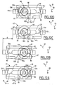
- FIGS. 12A to 12D show diagrammatically the different relative positions occupied by finger 49 with respect to the recess 51, during the different phases of an unlocking operation.
- barrel 46 has rotated a total of 335 ° in direction 81 from the position of FIG. 12A.
- finger 49 remained trapped in the housing 50, and pushed the wall 50a to the right of the figure to move the drive member 47 in the unlocking direction, opposite to direction 13 of locking, to the right of the figure, of a length A equal to the sliding of the bolt 40 between its two locked (figure 2) and unlocked positions (figure 3).
- Finger 49 is now in position 49c in which it is no longer engaged with the wall 50a.
- barrel 46 has rotated a total of 540 °, and finger 49 is now in position 49d in abutment against the wall 51d opposite the wall 51a, and against the wall 82 located in the extension of wall 80.
- the finger 49 For the reverse locking operation, rotates the barrel 46 in the opposite direction 83.
- the finger 49 Starting from position 49d, arrives in the position 49c in which the wall 50a leaves it enter the housing 50 where it abuts against the wall 50b.
- the finger 49 goes from position 49c to position 49b and pushes back in the locking direction 13, to the left in the figure, the wall 50b and the entire organ 47 on the same distance A.
- finger 49 is no longer engaged with the wall 50b, leaves housing 50 and can return freely at position 49a.
- the member 47 and the slide 4 have complementary means to conjugation of arranged forms so as to transform a displacement in direction longitudinal 5 of the drive member 47 at the start of an unlocking operation by moving the slide 4 in direction 15 perpendicular to the outer wall 9 of the housing 3.
- the slide 4 has a stud 52 whose face transverse 53 facing the locking direction 13 of the slide 4 is inclined relative to said perpendicular direction 15 and extends in direction 13 locking and inward of the housing 3.
- the drive member 47 has a face complementary 54 inclined substantially in the same direction so as to move the slide 4 in the direction 15 towards the inside of the box 3 at the start of an operation to unlock the slide 4 at key 45.
- the face 54 of the drive member 47 belongs to a lever element 55 carried by a arm 56 of organ 47.
- the lever 55 is retained between the pad 52 and a stop 57 of the slide 4, which means that the lever 55 transversely to the slide 4.
- the surface 58 of the lever 55 facing the outer plate 9 of the housing is located opposite a corresponding surface 59 of the slide 4.
- the distance between the two surfaces 58 and 59 is slightly greater than the height C of the contact area between edge 12 and the shoulder or edge 11a of the element 11, and either by example equal to C + ⁇ , as shown schematically in Figure 11.
- lever 55 can be move in the unlocking direction, opposite to the direction lock 13, of sufficient length function the inclination of the inclined faces 53 and 54, for lift the block 52, immobilized in the direction longitudinal, from a distance at least equal to C + ⁇ .
- the slide 4 has, above of element 11, a tab 61 extending in the longitudinal direction 5 of the housing in the opposite direction in the locking direction 13.
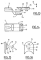
- the tab 61 has at its free end, at less a conformation 62 adapted to come into grip elastic, respectively in the position locked and in the unlocked position of the slide 4, with complementary conformations 63 and 64 integral or forming part of the folds 29 and 30 constituting the bottom of the housing 3.
- the tab 61 comprises two conformations 62, located respectively near the lateral longitudinal walls 25 and 26 of the housing 3.
- the conformations 62 are here convex outgrowths substantially spherical in shape.
- folds 29 and 30 each have a conformation 63 and a conformation 64, produced here in the form of a concave recess of substantially spherical shape.
- Conformations 63 and 64 are obviously spaced from each other, in the direction longitudinal 5 of the housing 3, from a distance corresponding to the displacement of the slide 4 between its respective locked positions, diagrammed in lines full in Figure 13, and unlocked, shown schematically at dashes to this same figure. Conformations 63 and 64 are advantageously provided on arms 65 extending longitudinally under the folds 29 and 30 and fixed in some way under these folds.
- the arms 65 can advantageously belong to a fixing member adapted to fix the end housing 3 at the corresponding end of the light 16 of the wall 17 of the opening.
- the slide 4 which has been described above can advantageously be produced by injection molding under hot pressure of a plastic material.
- the paw 61 performed in this way has a force of elastic return sufficient to perform the functions described above.
- the head of the screw 43 for locking the bolt 40 can advantageously be hidden by a cover 66.
- the cover 66 can advantageously be made in one piece with the slide 4 to which it can be connected by a hinge 67 constituted by a thinned part of the plastic.
- the cache 66 has a rectangular shape adapted to the rectangular shape shown in Figures 1 to 6 of light 8 of the lock 1.
- the cover 68 has two ends transverse rounded parallel adapted to the case where the lumen 8 has semi-circular longitudinal ends.
- the cover 68 has, on its face directed towards inside the slide, two claws 69 fitted each of a lug 70 adapted to engage with additional conformations not shown from slide to removably fix the cover 68 slider audit 4.
- the cover 68 comprises also an elongated finger 71 carrying at its end free two tabs 72 forming an arrowhead adapted to be folded down along finger 71 to penetrate a complementary hole, not shown, of the slide 4 and move away from the finger to retain it in the hole, in order to retain the cover 68 on the slide during actuation of screw 43.
- the locking fitting 101 for sliding door 2, window or the like includes a sliding assembly 4 movable in the longitudinal direction 5 of the housing 3 and carrying a bolt 40, an operating member 7 for actuating the sliding assembly 4 from the wall 17 on the side inside of the opening 2, and means for actuating the sliding assembly 4 from the wall 102 on the side outside of the opening 2 by means of a barrel 46 of lock driven by a key 45.
- the sliding assembly 4 shown in the figures is substantially identical to the slide 4 described in reference to Figures 1 to 16, but could be different from this one.
- the assembly sliding 4 may not have a projecting element 11 adapted to lock the slide 4 in its position locked.
- the bolt 40 can be of any type, carried by a bolt holder 6 of any type.
- the fitting 101 includes a drive member 103 movable in the longitudinal direction 5 of the housing 3 relative to said housing 3 and comprising, on the one hand, adapted means to cooperate with complementary means that are united with the barrel 46 to allow said member to be moved 103 in one direction 13 (the meaning of locking the bolt) or in the other using the key 45, on the other hand, means adapted to cooperate with additional means of the sliding assembly 4 for allow to move said sliding assembly 4 in one direction 13 or the other by means of the key 45.
- a drive member 103 movable in the longitudinal direction 5 of the housing 3 relative to said housing 3 and comprising, on the one hand, adapted means to cooperate with complementary means that are united with the barrel 46 to allow said member to be moved 103 in one direction 13 (the meaning of locking the bolt) or in the other using the key 45, on the other hand, means adapted to cooperate with additional means of the sliding assembly 4 for allow to move said sliding assembly 4 in one direction 13 or the other by means of the key 45.
- the barrel 46 is inserted into the body of a handle exterior, shown diagrammatically at 104.
- the handle 104 is fixed to the wall 102, in an inviolable manner from the outside, by means of fixing screws 105 allowing pinch the wall 102 between a fixing tab 106 and the handle 104.
- an axis 108 allows to pivotally attach a tab 109 which is will see the function later.
- the drive member 103 has on its face 110 facing the sliding assembly 4 of conformations 111 (see figure 22), 112 (see figure 23) adapted to come into conformation complementary 53, 113 of the sliding assembly 4.
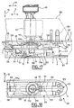
- the sliding assembly 4 comprises, on its face 10 adjacent to the cleanliness plate 9 (or wall exterior) of the housing 3, an element 11 projecting towards said plate 9 adapted to snap into place in the locked position of the bolt, shown in Figures 17 and 18, and under the action of elastic means 114, against the edge 12 of a corresponding transverse edge of the light 8 formed in the cleanliness plate 9.
- the drive member 103 and the assembly sliding 4 comprise complementary means 53, 111 with conjugation of forms arranged so as to transform a displacement in longitudinal direction 5 of the drive member 103, at the start of an operation unlocking, in one movement of the assembly sliding 4 in direction 15 perpendicular to the cleanliness plate 9 of the housing 3 towards the inside of said housing 3.
- the sliding assembly 4 shown in the figures includes, as already described above, a pad 52 with an inclined transverse face 53.
- the drive member 103 is a plate 103 (see figures 22 and 23) adapted to slide along the outer edges 140 of the folds 29, 30 of the walls longitudinal side 25, 26 of the housing 3.
- the plate 103 is adapted to slide between the housing 3 and a guide member 115, shown in particular in Figure 19, integral with the housing 3 and extending along the internal face 116 of wall 102, i.e. the face of wall 102 facing inward of sash 2 (see figure 17).
- the guide member 115 is fixed to a binding 117 comprising means for engaging, on the one hand, with the housing 3, on the other hand, with the light 16 made in the wall 17 on the inside of the opening 2, for snap-fastening the housing 3 to the wall 17 on the inner side of the opening 2.
- a fastener is described in the patent application French 97-04065 in the name of the plaintiff.
- the organ fixing 117 comprises a central body 118 whose cross section corresponds substantially to the cross section of the housing 3, which is adapted to penetrate inside the housing 3, and whose surface 119 is supported under the folds 29, 30 of the walls longitudinal side 25, 26 of the housing 3 (see Figures 19 and 21).
- the fixing member 117 To engage with the light 16 provided in the wall 17 of the opening 2, the fixing member 117 has a re-entrant shoulder 120 associated with a ramp 121 which makes it possible to wedge the wall 17 between the ramp 121 and the cleanliness plate 9 against the shoulder 120.
- the body 118 comprises an internal ramp 122 adapted to cooperate with the elastic tab 114 of the sliding assembly 4.
- the end 114a of the elastic tab 114 is not constrained or not significantly constrained by the ramp 122 and does not exercise significantly any solicitation of the projecting element 11 outwards from the housing.
- the guide member 115 is fixed to the fixing 117, for example by rivets shown schematically in 123 in Figures 17 to 21.
- the plate 103 has on its face 110 adjacent to the folds 29, 30 of the housing 3 at least one stud 126, 127 in projection towards the housing 3 for the drive of the sliding assembly 4.
- the plate 103 is symmetrical about a transverse plane of symmetry 124 perpendicular to the longitudinal direction 5 of the housing 3.
- each stud 126 has a inclined face 111 corresponding to the conformation 54 above to cooperate with the conformation 53 of the stud 52 of the sliding assembly 4.
- each pin 127 has a face 112 parallel to the plane of transverse symmetry 124, since it is not necessary to transform, at the start of a unlocking, a slight longitudinal movement of the plate 103 in a displacement in direction 15 of the sliding assembly 4.
- the symmetry of the plate 103 with respect to the plane transverse 124 allows to insert the plate 103 between the guide member 115 and the housing 3 on the site, by adapting the position of the barrel 46 and that of the plate 103 at the position of the opening with respect to the sleeping.
- the plate 103 is adapted to be introduced into the transverse direction 18 of the housing 3 between the member guide 115 and the housing 3 (see Figure 18).
- the longitudinal side walls 25, 26 for this purpose have notches 128 for the passage nipples 126, 127.
- the fitting 101 comprises means latching to retain the plate 103 in its operating position, between the guide member 115 and the housing 3.
- the plate 103 comprises, at each end in the longitudinal direction 5 of the housing, at least one elastic tab 129 extending in said longitudinal direction 5 and towards the guide member 115.
- the guide member 115 comprises, for each elastic tab 129, a groove 130 extending in the longitudinal direction 5 of the housing 3 and adapted to receive the corresponding elastic tab 129 for guide the plate 103 in its movements from sliding in the longitudinal direction 5 of the housing 3.
- the elastic tabs 129 can be folded down towards the housing 3, in position 129a shown in dashes in Figure 22, to allow the introduction of the plate 103 between the housing 3 and the guide member 115.
- the guide member 115 comprises two openings or through slots 131 formed, from the surface 115a of the member 115 adjacent to the wall 102, respectively to the right of the positions occupied by the two legs 129 in the position of the plate 103 corresponding to the locked position of the bolt and shown in Figures 17 and 18.
- each groove 130 has a slight depression 130a at the level of the position of the corresponding leg 129 when the plate 103 is in the position of figures 17 and 18 corresponding to the locked position of the bolt.
- These indentations 130a define this position of the plate 103 with the precision necessary to obtain with certainty the latching of the protruding element 11 in light 8 when you want to lock the bolt using the key 45.
- Similar conformations 130a are also provided for the positions of the legs 129 of the plate 103 corresponding to the open position of the bolt.
- the plate 103 has on its face 125 facing the guide member 115, on both sides from its transverse plane of symmetry 124, two ribs 132, 133 extending parallel to said plane 124 and to the transverse direction 18 of the fitting 101, the faces opposite the ribs 132 and 133 forming the walls 50a, 50b above.
- Each rib 132, 133 has a shape of L and includes a respective rib element 137, 138 extending in the longitudinal direction 5 and defining the respective wall 80, 82 above.
- the two ribs 132 and 133 are thus adapted to cooperate with the finger 49 secured to a disc 48 driven by the barrel 46.
- the length and the spacing of the two ribs 132, 133 are determined so as to allow finger 49 to enter housing 50 between the two ribs 132, 133, when the disc 48 turns in one direction or the other, to lean on the wall 50a, 50b of the second rib 132, 133 encountered, and to push, through this second rib 132.133, the plate 103 in the corresponding direction of the longitudinal direction 5 on a predetermined distance in order to move the whole sliding 4 from locked position to position open the bolt 40 or vice versa, then allow finger 49 to escape from said second rib 132, 133 encountered to authorize the end of the rotation of the barrel 46.
- the disc 48 is suitable to be received in the housing circular 134 formed in the guide member 115 in look at the plate 103.
- the disc 48 has axially a flattened open 46a in which is adapted to penetrate the tongue 109 to allow actuation of the disc 48 by the barrel 46.
- the plate 103 provided with two pins 126 allows thus to order by means of the key 45, from outside of the opening 2, the displacements of the assembly sliding in the locking direction 13 to its locked locked position in Figure 17.
- Element 11 engages with edge 12 under the action of elastic means 114.
- the plate 103 likewise makes it possible to control the movement in the opposite direction using the key 45.
- the surface 111 of the stud 126 acting on the surface 53 of the pad 52 extracts the projecting element 11 from its position in engagement with the edge 12 of the light 8.
- a fitting 101 of structure has thus been described simple and modular allowing to choose on site the functions to be obtained: locking by means of the key, locking using the key, automatic control blocking in the locked position, etc ...
- the elements constituting the fitting 101 are adaptable to all ranges and all materials opening, and to all dimensions.
- a handle of any type other than the one described above for example a lever or rocker or push handle, through light 8.
- a slide and a housing comprising the fingers 34 and bulges 36, or the tab 61 and the conformations 62, 63 and 64, without having a suitable projecting element 11 to protrude by light 8 in the position slider locked 4.
- the bolt holder 6 and the bolt 40 can be of a any type.
- the guide member 115 could be fixed to the case 3 in another way.
- the fixation of the organ guide 115, by rivets easy to install, on the fixing member 117 makes it possible not to use the member guide 115 only in the case where a lock for control, from outside the opening, of the sliding assembly by means of the key 45.
Landscapes
- Engineering & Computer Science (AREA)
- Structural Engineering (AREA)
- Lock And Its Accessories (AREA)
- Wing Frames And Configurations (AREA)
- Window Of Vehicle (AREA)
- Power-Operated Mechanisms For Wings (AREA)
- Special Wing (AREA)
- Cartons (AREA)
- Time Recorders, Dirve Recorders, Access Control (AREA)
Abstract
Description
- la figure 1 est une vue de face, avec arrachement, d'une ferrure selon un mode de réalisation de la présente invention, le coulisseau étant schématisé dans sa position verrouillée ;
- la figure 2 est une vue en coupe selon II-II à la figure 1, le coulisseau étant représenté dans sa position verrouillée ;
- la figure 3 est une vue semblable à la figure 2, le coulisseau étant dans sa position déverrouillée ;
- la figure 4 est une vue schématique en coupe selon IV-IV à la figure 2 ;
- la figure 5 est une vue en perspective du coulisseau du mode de réalisation des figures 1 à 4, le coulisseau étant représenté avec l'organe de manoeuvre dirigé vers le haut de la figure et vu par l'avant comme lorsqu'il est installé sur un ouvrant coulissant ;
- la figure 6 est une vue semblable à la figure 5, l'organe de manoeuvre étant dirigé dans le sens opposé ;
- la figure 7 est une vue schématique semblable à la figure 2 d'un autre mode de réalisation de l'invention ;
- la figure 8 est une vue schématique semblable à la figure 3 du mode de réalisation de la figure 7 ;
- la figure 9 est une vue agrandie d'un détail de la figure 2 suivant un autre mode de réalisation de la présente invention comportant une serrure dans le plan de la figure ;
- la figure 10 est une vue en perspective éclatée du mode de réalisation représenté à la figure 9 ;
- la figure 11 est une vue agrandie du détail XI à la figure 9 ;
- les figures 12A à 12D sont des vues de dessus agrandies de l'organe d'entraínement du mode de réalisation des figures 9 à 11 représentant les différentes phases d'une opération de déverrouillage, dans lesquelles le barillet est représenté respectivement dans sa position de départ (O°) et après des rotations de 205°, 335° et 540°;
- la figure 13 est une vue semblable à la figure 2 d'un détail d'un autre mode de réalisation de la présente invention ;
- la figure 14 est une vue de dessus du détail représenté à la figure 13 ;
- les figures 15 et 16 sont respectivement une vue de profil et une vue de dessus d'une variante d'un détail de la figure 5 ;
- la figure 17 est une vue partielle agrandie semblable à la figure 2, d'un autre mode de réalisation de la ferrure selon la présente invention, l'ensemble coulissant et l'organe d'entraínement étant dans la position correspondant à la position verrouillée du pêne ;
- la figure 18 est une vue de dessus de la figure 17, la ferrure étant représentée seule, hors de l'ouvrant, par souci de clarté ;
- la figure 19 est une vue d'un détail de la figure 17 représentant l'organe de fixation du profilé et l'organe de guidage ;
- la figure 20 est une vue semblable à la figure 17, la paroi du côté extérieur de l'ouvrant n'étant pas représentée, et l'ensemble coulissant et l'organe d'entraínement étant dans la position correspondant à la position ouverte du pêne ;
- la figure 21 est une vue semblable à la figure 20, avec arrachements, illustrant les moyens de coopération de l'organe d'entraínement respectivement avec l'organe de guidage et l'ensemble coulissant ;
- la figure 22 est une vue d'un détail des figures 17, 20 et 21 représentant l'organe d'entraínement vu en élévation ;
- la figure 23 est une vue partielle semblable à la figure 22 d'un autre mode de réalisation de l'organe d'entraínement.
Claims (8)
- Ferrure (1, 101) de verrouillage pour ouvrant coulissant (2) de porte, fenêtre ou analogue, comprenant un boítier (3) adapté à être introduit dans une ouverture (16) ménagée dans la paroi (17) du côté intérieur de l'ouvrant coulissant (2), un ensemble coulissant (4) qui est mobile dans la direction longitudinale (5) du boítier (3) et qui comporte un organe de manoeuvre (7) pour actionner l'ensemble coulissant (4) depuis ladite paroi (17), ledit organe de manoeuvre (7) étant accessible à travers une lumière longitudinale (8) ménagée sur la paroi extérieure (9) du boítier (3), l'ensemble coulissant (4) comportant un porte-pêne (6) adapté à porter un pêne (40) et à recevoir une vis (43) de blocage du pêne (40) accessible par la lumière (8), l'ensemble coulissant (4) étant conformé de manière telle que la tête de la vis (43) est masquée par un cache (66, 68) amovible solidaire dudit ensemble coulissant (4), caractérisée en ce que le cache (66, 68) et l'ensemble coulissant (4) comprennent des moyens adaptés à retenir le cache (66, 68) sur l'ensemble coulissant (4) pendant l'actionnement de la vis (43).
- Ferrure de verrouillage selon la revendication 1, l'ensemble coulissant (4) étant réalisé en matière plastique, caractérisée en ce que le cache (66) est réalisé d'une seule pièce avec l'ensemble coulissant (4) auquel il est relié par une charnière (67) constituée par exemple par une partie amincie de la matière plastique.
- Ferrure de verrouillage selon la revendication 1, caractérisée en ce que le cache (68) comporte en outre un doigt (71) portant à son extrémité libre deux languettes (72) afin de retenir le cache (68) sur l'ensemble coulissant (4) pendant l'actionnement de la vis (43).
- Ferrure de verrouillage selon la revendication 3, caractérisée en ce que les deux languettes (72) forment une pointe de flèche et sont adaptées à être rabattues le long du doigt (71) pour pénétrer dans un trou complémentaire de l'ensemble coulissant (4) et à s'écarter du doigt (71) pour retenir ledit doigt dans ledit trou.
- Ferrure de verrouillage selon la revendication 3 ou 4, caractérisée en ce que le cache (68) comporte, sur sa face dirigée vers l'intérieur de l'ensemble coulissant (4), des griffes (69) adaptées à venir en prise avec des conformations complémentaires de l'ensemble coulissant (4) pour fixer de façon amovible le cache (68) audit ensemble coulissant (4).
- Ferrure de verrouillage selon la revendication 5, caractérisée en ce que le cache (68) comporte deux griffes (69) munies chacune d'un ergot (70) adapté à venir en prise avec des conformations complémentaires de l'ensemble coulissant (4).
- Ferrure de verrouillage selon l'une des revendications 5 ou 6, caractérisée en ce que le doigt (71) est décalé transversalement par rapport aux griffes (69).
- Ferrure de verrouillage selon l'une quelconque des revendications précédentes, caractérisée en ce que le cache (66, 68) a des extrémités tranversales ayant une forme adaptée à la forme des extrémités longitudinales de la lumière (8).
Applications Claiming Priority (5)
| Application Number | Priority Date | Filing Date | Title |
|---|---|---|---|
| FR9704064 | 1997-04-03 | ||
| FR9704064A FR2761718B1 (fr) | 1997-04-03 | 1997-04-03 | Ferrure de verrouillage pour ouvrant coulissant de porte, fenetre ou analogue |
| FR9707934A FR2761724B1 (fr) | 1997-04-03 | 1997-06-25 | Ferrure de verrouillage pour ouvrant coulissant de porte, fenetre ou analogue |
| FR9707934 | 1997-06-25 | ||
| EP19980400699 EP0869240B1 (fr) | 1997-04-03 | 1998-03-25 | Ferrure de verrouillage pour ouvrant coulissant de porte, fenêtre ou analogue |
Related Parent Applications (1)
| Application Number | Title | Priority Date | Filing Date |
|---|---|---|---|
| EP19980400699 Division EP0869240B1 (fr) | 1997-04-03 | 1998-03-25 | Ferrure de verrouillage pour ouvrant coulissant de porte, fenêtre ou analogue |
Publications (2)
| Publication Number | Publication Date |
|---|---|
| EP1288405A1 true EP1288405A1 (fr) | 2003-03-05 |
| EP1288405B1 EP1288405B1 (fr) | 2006-09-06 |
Family
ID=26233438
Family Applications (2)
| Application Number | Title | Priority Date | Filing Date |
|---|---|---|---|
| EP20020020755 Expired - Lifetime EP1288405B1 (fr) | 1997-04-03 | 1998-03-25 | Ferrure de verrouillage pour ouvrant coulissant de porte, fenêtre ou analogue |
| EP19980400699 Expired - Lifetime EP0869240B1 (fr) | 1997-04-03 | 1998-03-25 | Ferrure de verrouillage pour ouvrant coulissant de porte, fenêtre ou analogue |
Family Applications After (1)
| Application Number | Title | Priority Date | Filing Date |
|---|---|---|---|
| EP19980400699 Expired - Lifetime EP0869240B1 (fr) | 1997-04-03 | 1998-03-25 | Ferrure de verrouillage pour ouvrant coulissant de porte, fenêtre ou analogue |
Country Status (10)
| Country | Link |
|---|---|
| US (1) | US6050617A (fr) |
| EP (2) | EP1288405B1 (fr) |
| CN (1) | CN1197144A (fr) |
| AT (2) | ATE243292T1 (fr) |
| BR (1) | BR9801223A (fr) |
| DE (2) | DE69835839T2 (fr) |
| ES (2) | ES2272625T3 (fr) |
| FR (1) | FR2761724B1 (fr) |
| PT (2) | PT1288405E (fr) |
| TW (1) | TW405011B (fr) |
Cited By (3)
| Publication number | Priority date | Publication date | Assignee | Title |
|---|---|---|---|---|
| EP1528193A1 (fr) * | 2003-10-31 | 2005-05-04 | Ferco International Ferrures et Serrures de Bâtiment Société par actions simplifiée | Ferrure de verrouillage pour ouvrant coulissant. |
| EP1528191A1 (fr) * | 2003-10-31 | 2005-05-04 | Ferco International Ferrures et Serrures de Bâtiment Société par actions simplifiée | Ferrure de verrouillage pour ouvrant coulissant. |
| EP1528192A1 (fr) * | 2003-10-31 | 2005-05-04 | Ferco International Ferrures et Serrures de Bâtiment Société par actions simplifiée | Ferrure de verrouillage pour ouvrant coulissant. |
Families Citing this family (21)
| Publication number | Priority date | Publication date | Assignee | Title |
|---|---|---|---|---|
| FR2791384B1 (fr) * | 1999-03-23 | 2001-04-27 | Ferco Int Usine Ferrures | Ferrure de commande pour un ouvrant coulissant |
| FR2814189B1 (fr) * | 2000-09-15 | 2002-11-29 | Ferco Int Usine Ferrures | Ferrure de verrouillage pour ouvrant coulissant |
| FR2817894B1 (fr) * | 2000-12-13 | 2003-08-08 | Ferco Int Usine Ferrures | Organe de commande pour ouvrant coulissant |
| CY2516B1 (fr) * | 2004-12-29 | 2006-02-08 | A C Technometal Ltd | |
| ITRA20050007A1 (it) * | 2005-03-14 | 2006-09-15 | Erreti Srl | Maniglia a vaschetta |
| ITRA20050009A1 (it) * | 2005-03-14 | 2006-09-15 | Erreti Srl | Maniglia a vaschetta |
| WO2006120715A1 (fr) * | 2005-05-12 | 2006-11-16 | Erreti S.R.L. | Poignee evidee |
| ITTO20050772A1 (it) * | 2005-10-31 | 2007-05-01 | Savio Spa | Dispositivo di riallineamento della serratura di un serramento scorrevole |
| CN101148960B (zh) * | 2006-09-22 | 2011-08-31 | 林振豊 | 铝门窗横拉及外推共用窗限制锁 |
| CN101435297B (zh) * | 2007-11-14 | 2012-11-07 | 林振豊 | 铝门窗防盗及横拉开启限制锁 |
| US8584426B2 (en) | 2010-06-04 | 2013-11-19 | Milgard Manufacturing Incorporated | Sash binder |
| US9091103B2 (en) * | 2012-03-21 | 2015-07-28 | Frank Herman Buzz, III | Sliding glass door safety latch |
| CN103631456B (zh) | 2012-08-24 | 2017-07-04 | 深圳欧菲光科技股份有限公司 | 薄膜感应器、包含该感应器的电容触摸屏及其制作方法和终端产品 |
| CN103631455A (zh) * | 2012-08-24 | 2014-03-12 | 深圳欧菲光科技股份有限公司 | 薄膜感应器、包含该感应器的电容触摸屏及其制作方法和终端产品 |
| US9510456B2 (en) | 2012-11-09 | 2016-11-29 | Shenzhen O-Film Tech Co., Ltd. | Transparent conductor and preparation method thereof |
| GR1008852B (el) * | 2015-03-09 | 2016-09-16 | Αθανασιος Παυλου Λεονταριδης | Εξωτερικο κλειθρο δυο πειρων για συρομενα φυλλα θυρων ή παραθυρων, με διαταξη κλειδιου ασφαλισης σε θεση κλειδωματος |
| US10513874B2 (en) * | 2016-06-16 | 2019-12-24 | Dometic Sweden Ab | Lock assembly |
| DE102016012609A1 (de) * | 2016-10-19 | 2018-04-19 | Roto Frank Aktiengesellschaft | Schloss für ein Verschlusselement einer Immobilie sowie entsprechendes Verschlusselement |
| EP3739151B1 (fr) * | 2019-05-17 | 2024-05-22 | Jofebar S.A. | Mécanisme de verrouillage pour portes et fenêtres coulissantes |
| CN110424835A (zh) * | 2019-07-22 | 2019-11-08 | 佛山市宏进豪金属制品有限公司 | 一种隐藏式拉手一体化锁具 |
| AU2021221630A1 (en) * | 2021-08-25 | 2023-03-16 | Assa Abloy New Zealand Limited | Lock with securable retainer for sliding panels and installation method |
Citations (6)
| Publication number | Priority date | Publication date | Assignee | Title |
|---|---|---|---|---|
| EP0044264A1 (fr) * | 1980-07-11 | 1982-01-20 | FERCO INTERNATIONAL Usine de Ferrures de BÀ¢timent Société à responsabilité limitée | Ferrure de verrouillage d'un ouvrant coulissant de fenêtre, porte ou analogue |
| FR2582710A1 (fr) | 1985-05-30 | 1986-12-05 | Ferco Int Usine Ferrures | Loquet pour ouvrant coulissant comportant un pene a crochet coulissant |
| EP0431518A2 (fr) * | 1989-12-04 | 1991-06-12 | Bauer, Hans-Jürgen | Serrure pour meubles |
| US5301989A (en) * | 1993-03-09 | 1994-04-12 | Truth Hardware Corporation | Tilt lock for double-hung windows |
| EP0593242A2 (fr) * | 1992-10-12 | 1994-04-20 | International Business Machines Corporation | Boîtier avec un couvercle |
| GR2001772Y (en) * | 1995-12-06 | 1996-04-23 | Andreas Konstantinidis | Safety lock for sliding doors |
Family Cites Families (19)
| Publication number | Priority date | Publication date | Assignee | Title |
|---|---|---|---|---|
| US2789852A (en) * | 1955-11-18 | 1957-04-23 | Arthur R Adams | Lock mechanism |
| US2990208A (en) * | 1959-08-06 | 1961-06-27 | Daryl Ind Inc | Latch assembly for closures |
| US3120748A (en) * | 1960-10-11 | 1964-02-11 | Adams Rite Mfg Company | Narrow stile lock and actuator |
| US3353855A (en) * | 1965-04-20 | 1967-11-21 | Crossly Window Corp | Lock mechanism for a sliding panel |
| US3390557A (en) * | 1965-10-06 | 1968-07-02 | Amerock Corp | Door latch |
| US3904229A (en) * | 1974-05-23 | 1975-09-09 | Ideal Security Hardware Co | Sliding door lock |
| GB1566403A (en) * | 1976-01-29 | 1980-04-30 | Schlegel Uk Ltd | Flush set lock for sliding doors |
| US4024739A (en) * | 1976-02-13 | 1977-05-24 | Nathan Kaufman | Sliding glass door lock |
| US4436329A (en) * | 1982-02-23 | 1984-03-13 | Metzger Thomas J | Locking mechanism |
| US4754624A (en) * | 1987-01-23 | 1988-07-05 | W&F Manufacturing | Lock assembly for sliding doors |
| US4790157A (en) * | 1987-05-18 | 1988-12-13 | Andrew Lin | Locking apparatus for sliding door |
| FR2632343B1 (fr) * | 1988-06-02 | 1990-08-17 | Ferco Int Usine Ferrures | Ferrure de verrouillage pour ouvrant coulissant |
| US4912950A (en) * | 1988-10-03 | 1990-04-03 | Illinois Tool Works, Inc. | Lockable buckle |
| US5145221A (en) * | 1990-07-17 | 1992-09-08 | Chicago Electrical Tool Company, Inc. | Sliding latch lock |
| US5125703A (en) * | 1991-08-06 | 1992-06-30 | Sash Controls, Inc. | Door hardware assembly |
| US5158329A (en) * | 1991-09-20 | 1992-10-27 | Southco, Inc. | Slam latch |
| US5201557A (en) * | 1991-09-24 | 1993-04-13 | Southco, Inc. | Slide fastener |
| FR2700577B1 (fr) * | 1993-01-18 | 1995-03-24 | Charles Prunet | Serrure pour coulissant munie de moyens permettant au coulisseau d'atteindre automatiquement les positions d'ouverture et de fermeture. |
| GB9319006D0 (en) * | 1993-09-14 | 1993-10-27 | Schlegel Uk Holdings | Lock for sliding door |
-
1997
- 1997-06-25 FR FR9707934A patent/FR2761724B1/fr not_active Expired - Fee Related
-
1998
- 1998-03-25 PT PT02020755T patent/PT1288405E/pt unknown
- 1998-03-25 DE DE1998635839 patent/DE69835839T2/de not_active Expired - Fee Related
- 1998-03-25 AT AT98400699T patent/ATE243292T1/de not_active IP Right Cessation
- 1998-03-25 PT PT98400699T patent/PT869240E/pt unknown
- 1998-03-25 EP EP20020020755 patent/EP1288405B1/fr not_active Expired - Lifetime
- 1998-03-25 EP EP19980400699 patent/EP0869240B1/fr not_active Expired - Lifetime
- 1998-03-25 AT AT02020755T patent/ATE338867T1/de not_active IP Right Cessation
- 1998-03-25 ES ES02020755T patent/ES2272625T3/es not_active Expired - Lifetime
- 1998-03-25 ES ES98400699T patent/ES2201419T3/es not_active Expired - Lifetime
- 1998-03-25 DE DE1998615573 patent/DE69815573T2/de not_active Expired - Fee Related
- 1998-04-02 TW TW87104991A patent/TW405011B/zh not_active IP Right Cessation
- 1998-04-02 CN CN98106155A patent/CN1197144A/zh active Pending
- 1998-04-03 BR BR9801223A patent/BR9801223A/pt not_active Application Discontinuation
- 1998-04-03 US US09/054,772 patent/US6050617A/en not_active Expired - Fee Related
Patent Citations (7)
| Publication number | Priority date | Publication date | Assignee | Title |
|---|---|---|---|---|
| EP0044264A1 (fr) * | 1980-07-11 | 1982-01-20 | FERCO INTERNATIONAL Usine de Ferrures de BÀ¢timent Société à responsabilité limitée | Ferrure de verrouillage d'un ouvrant coulissant de fenêtre, porte ou analogue |
| FR2582710A1 (fr) | 1985-05-30 | 1986-12-05 | Ferco Int Usine Ferrures | Loquet pour ouvrant coulissant comportant un pene a crochet coulissant |
| EP0431518A2 (fr) * | 1989-12-04 | 1991-06-12 | Bauer, Hans-Jürgen | Serrure pour meubles |
| EP0593242A2 (fr) * | 1992-10-12 | 1994-04-20 | International Business Machines Corporation | Boîtier avec un couvercle |
| US5301989A (en) * | 1993-03-09 | 1994-04-12 | Truth Hardware Corporation | Tilt lock for double-hung windows |
| GR2001772Y (en) * | 1995-12-06 | 1996-04-23 | Andreas Konstantinidis | Safety lock for sliding doors |
| GB2310453A (en) * | 1995-12-06 | 1997-08-27 | A C Technometal Ltd | Locking mechanisms for slidable doors or windows |
Cited By (6)
| Publication number | Priority date | Publication date | Assignee | Title |
|---|---|---|---|---|
| EP1528193A1 (fr) * | 2003-10-31 | 2005-05-04 | Ferco International Ferrures et Serrures de Bâtiment Société par actions simplifiée | Ferrure de verrouillage pour ouvrant coulissant. |
| EP1528191A1 (fr) * | 2003-10-31 | 2005-05-04 | Ferco International Ferrures et Serrures de Bâtiment Société par actions simplifiée | Ferrure de verrouillage pour ouvrant coulissant. |
| EP1528192A1 (fr) * | 2003-10-31 | 2005-05-04 | Ferco International Ferrures et Serrures de Bâtiment Société par actions simplifiée | Ferrure de verrouillage pour ouvrant coulissant. |
| FR2861787A1 (fr) * | 2003-10-31 | 2005-05-06 | Ferco Int Usine Ferrures | Ferrure de verrouillage pour ouvrant coulissant |
| FR2861786A1 (fr) * | 2003-10-31 | 2005-05-06 | Ferco Int Usine Ferrures | Ferrure de verrouillage pour ouvrant coulissant |
| FR2861788A1 (fr) * | 2003-10-31 | 2005-05-06 | Ferco Int Usine Ferrures | Ferrure de verrouillage pour ouvrant coulissant |
Also Published As
| Publication number | Publication date |
|---|---|
| FR2761724B1 (fr) | 2000-02-04 |
| FR2761724A1 (fr) | 1998-10-09 |
| DE69815573D1 (de) | 2003-07-24 |
| EP0869240B1 (fr) | 2003-06-18 |
| DE69835839D1 (de) | 2006-10-19 |
| US6050617A (en) | 2000-04-18 |
| ATE338867T1 (de) | 2006-09-15 |
| ATE243292T1 (de) | 2003-07-15 |
| DE69835839T2 (de) | 2007-04-12 |
| PT1288405E (pt) | 2007-01-31 |
| DE69815573T2 (de) | 2004-04-29 |
| ES2272625T3 (es) | 2007-05-01 |
| ES2201419T3 (es) | 2004-03-16 |
| CN1197144A (zh) | 1998-10-28 |
| PT869240E (pt) | 2003-10-31 |
| BR9801223A (pt) | 1999-04-27 |
| EP1288405B1 (fr) | 2006-09-06 |
| EP0869240A1 (fr) | 1998-10-07 |
| TW405011B (en) | 2000-09-11 |
Similar Documents
| Publication | Publication Date | Title |
|---|---|---|
| EP0869240B1 (fr) | Ferrure de verrouillage pour ouvrant coulissant de porte, fenêtre ou analogue | |
| EP4093237B1 (fr) | Article de maroquinerie du type bagage | |
| EP0869239B1 (fr) | Ferrure de verrouillage pour ouvrant coulissant de porte, fenêtre ou analogue | |
| FR2777588A1 (fr) | Dispositif de verrouillage pour ouvrant coulissant | |
| EP1162334B1 (fr) | Serrure anti-glissement résistante au feu | |
| FR2761720A1 (fr) | Ferrure de verrouillage pour ouvrant coulissant | |
| EP0869243B1 (fr) | Ferrure pour ouvrant coulissant | |
| BE1015014A4 (fr) | Ferrure de verrouillage d'ouvrant dotee pour sa fixation de moyens d'appui interieur et exterieur decales et ouvrant equipe d'une telle ferrure. | |
| EP1880072B1 (fr) | Serrure a deux positions de blocage longitudinalement decalees | |
| FR2784132A1 (fr) | Ferrure de verrouillage pour ouvrant coulissant de porte, fenetre ou analogue | |
| EP4093235B1 (fr) | Article de maroquinerie du type bagage | |
| EP0070576B2 (fr) | Crémone, en particulier crémone-serrure pour porte, porte-fenêtre ou analogue | |
| EP1808557B1 (fr) | Ferrure de verrouillage | |
| FR2861789A1 (fr) | Serrure anti-panique multipoint reversible | |
| FR2780434A1 (fr) | Ferrure de verrouillage pour ouvrant coulissant de porte, fenetre ou analogue | |
| BE1017308A5 (fr) | Serrure. | |
| FR2863000A1 (fr) | Serrure de porte a empennage automatique | |
| EP4245949B1 (fr) | Dispositif de commande de verrouillage et de déverrouillage | |
| EP4093236B1 (fr) | Article de maroquinerie du type bagage | |
| EP1247927A1 (fr) | Pêne demi-tour réversible de serrure à mortaiser ou en applique | |
| FR2811696A1 (fr) | Ferrure de verrouillage d'ouvrant a mors d'appui interieur manoeuvrable en translation, procede de montage et ouvrant equipe d'une telle ferrure | |
| FR2696051A1 (fr) | Armoire à battant de porte équipé d'un détecteur de fermeture. | |
| EP0919682B1 (fr) | Boítier de commande pour crémone à têtière pour portes, fenêtres, porte-fenêtres ou analogue | |
| EP1106752B1 (fr) | Serrure résistante au feu | |
| FR2683579A1 (fr) | Agencement de verrouillage d'un organe mobile de fermeture d'une ouverture, telle qu'une porte. |
Legal Events
| Date | Code | Title | Description |
|---|---|---|---|
| PUAI | Public reference made under article 153(3) epc to a published international application that has entered the european phase |
Free format text: ORIGINAL CODE: 0009012 |
|
| AC | Divisional application: reference to earlier application |
Ref document number: 0869240 Country of ref document: EP Kind code of ref document: P |
|
| AK | Designated contracting states |
Kind code of ref document: A1 Designated state(s): AT BE CH DE DK ES FI GB GR IE IT LI NL PT SE |
|
| 17P | Request for examination filed |
Effective date: 20030208 |
|
| AKX | Designation fees paid |
Designated state(s): AT BE CH DE DK ES FI GB GR IE IT LI NL PT SE |
|
| 17Q | First examination report despatched |
Effective date: 20040331 |
|
| GRAP | Despatch of communication of intention to grant a patent |
Free format text: ORIGINAL CODE: EPIDOSNIGR1 |
|
| GRAS | Grant fee paid |
Free format text: ORIGINAL CODE: EPIDOSNIGR3 |
|
| GRAA | (expected) grant |
Free format text: ORIGINAL CODE: 0009210 |
|
| AC | Divisional application: reference to earlier application |
Ref document number: 0869240 Country of ref document: EP Kind code of ref document: P |
|
| AK | Designated contracting states |
Kind code of ref document: B1 Designated state(s): AT BE CH DE DK ES FI GB GR IE IT LI NL PT SE |
|
| PG25 | Lapsed in a contracting state [announced via postgrant information from national office to epo] |
Ref country code: IT Free format text: LAPSE BECAUSE OF FAILURE TO SUBMIT A TRANSLATION OF THE DESCRIPTION OR TO PAY THE FEE WITHIN THE PRESCRIBED TIME-LIMIT;WARNING: LAPSES OF ITALIAN PATENTS WITH EFFECTIVE DATE BEFORE 2007 MAY HAVE OCCURRED AT ANY TIME BEFORE 2007. THE CORRECT EFFECTIVE DATE MAY BE DIFFERENT FROM THE ONE RECORDED. Effective date: 20060906 Ref country code: IE Free format text: LAPSE BECAUSE OF FAILURE TO SUBMIT A TRANSLATION OF THE DESCRIPTION OR TO PAY THE FEE WITHIN THE PRESCRIBED TIME-LIMIT Effective date: 20060906 Ref country code: FI Free format text: LAPSE BECAUSE OF FAILURE TO SUBMIT A TRANSLATION OF THE DESCRIPTION OR TO PAY THE FEE WITHIN THE PRESCRIBED TIME-LIMIT Effective date: 20060906 Ref country code: NL Free format text: LAPSE BECAUSE OF FAILURE TO SUBMIT A TRANSLATION OF THE DESCRIPTION OR TO PAY THE FEE WITHIN THE PRESCRIBED TIME-LIMIT Effective date: 20060906 |
|
| REG | Reference to a national code |
Ref country code: GB Ref legal event code: FG4D Free format text: NOT ENGLISH |
|
| REG | Reference to a national code |
Ref country code: CH Ref legal event code: EP |
|
| REG | Reference to a national code |
Ref country code: IE Ref legal event code: FG4D Free format text: LANGUAGE OF EP DOCUMENT: FRENCH |
|
| REF | Corresponds to: |
Ref document number: 69835839 Country of ref document: DE Date of ref document: 20061019 Kind code of ref document: P |
|
| PG25 | Lapsed in a contracting state [announced via postgrant information from national office to epo] |
Ref country code: SE Free format text: LAPSE BECAUSE OF FAILURE TO SUBMIT A TRANSLATION OF THE DESCRIPTION OR TO PAY THE FEE WITHIN THE PRESCRIBED TIME-LIMIT Effective date: 20061206 Ref country code: DK Free format text: LAPSE BECAUSE OF FAILURE TO SUBMIT A TRANSLATION OF THE DESCRIPTION OR TO PAY THE FEE WITHIN THE PRESCRIBED TIME-LIMIT Effective date: 20061206 |
|
| GBT | Gb: translation of ep patent filed (gb section 77(6)(a)/1977) |
Effective date: 20061219 |
|
| REG | Reference to a national code |
Ref country code: PT Ref legal event code: SC4A Free format text: AVAILABILITY OF NATIONAL TRANSLATION Effective date: 20061221 |
|
| NLV1 | Nl: lapsed or annulled due to failure to fulfill the requirements of art. 29p and 29m of the patents act | ||
| REG | Reference to a national code |
Ref country code: IE Ref legal event code: FD4D |
|
| REG | Reference to a national code |
Ref country code: ES Ref legal event code: FG2A Ref document number: 2272625 Country of ref document: ES Kind code of ref document: T3 |
|
| PLBE | No opposition filed within time limit |
Free format text: ORIGINAL CODE: 0009261 |
|
| STAA | Information on the status of an ep patent application or granted ep patent |
Free format text: STATUS: NO OPPOSITION FILED WITHIN TIME LIMIT |
|
| 26N | No opposition filed |
Effective date: 20070607 |
|
| REG | Reference to a national code |
Ref country code: CH Ref legal event code: PL |
|
| GBPC | Gb: european patent ceased through non-payment of renewal fee |
Effective date: 20070325 |
|
| BERE | Be: lapsed |
Owner name: FERCO INTERNATIONAL FERRURES ET SERRURES DE BATIM Effective date: 20070331 |
|
| PG25 | Lapsed in a contracting state [announced via postgrant information from national office to epo] |
Ref country code: BE Free format text: LAPSE BECAUSE OF NON-PAYMENT OF DUE FEES Effective date: 20070331 |
|
| PG25 | Lapsed in a contracting state [announced via postgrant information from national office to epo] |
Ref country code: CH Free format text: LAPSE BECAUSE OF NON-PAYMENT OF DUE FEES Effective date: 20070331 Ref country code: LI Free format text: LAPSE BECAUSE OF NON-PAYMENT OF DUE FEES Effective date: 20070331 |
|
| PG25 | Lapsed in a contracting state [announced via postgrant information from national office to epo] |
Ref country code: GB Free format text: LAPSE BECAUSE OF NON-PAYMENT OF DUE FEES Effective date: 20070325 Ref country code: GR Free format text: LAPSE BECAUSE OF FAILURE TO SUBMIT A TRANSLATION OF THE DESCRIPTION OR TO PAY THE FEE WITHIN THE PRESCRIBED TIME-LIMIT Effective date: 20061207 |
|
| PGFP | Annual fee paid to national office [announced via postgrant information from national office to epo] |
Ref country code: PT Payment date: 20080225 Year of fee payment: 11 |
|
| PG25 | Lapsed in a contracting state [announced via postgrant information from national office to epo] |
Ref country code: AT Free format text: LAPSE BECAUSE OF NON-PAYMENT OF DUE FEES Effective date: 20070325 |
|
| PGFP | Annual fee paid to national office [announced via postgrant information from national office to epo] |
Ref country code: DE Payment date: 20090320 Year of fee payment: 12 |
|
| REG | Reference to a national code |
Ref country code: PT Ref legal event code: MM4A Free format text: LAPSE DUE TO NON-PAYMENT OF FEES Effective date: 20090925 |
|
| PG25 | Lapsed in a contracting state [announced via postgrant information from national office to epo] |
Ref country code: PT Free format text: LAPSE BECAUSE OF NON-PAYMENT OF DUE FEES Effective date: 20090925 |
|
| PG25 | Lapsed in a contracting state [announced via postgrant information from national office to epo] |
Ref country code: DE Free format text: LAPSE BECAUSE OF NON-PAYMENT OF DUE FEES Effective date: 20101001 |
|
| PGFP | Annual fee paid to national office [announced via postgrant information from national office to epo] |
Ref country code: ES Payment date: 20130326 Year of fee payment: 16 |
|
| PGFP | Annual fee paid to national office [announced via postgrant information from national office to epo] |
Ref country code: IT Payment date: 20140331 Year of fee payment: 17 |
|
| PG25 | Lapsed in a contracting state [announced via postgrant information from national office to epo] |
Ref country code: IT Free format text: LAPSE BECAUSE OF NON-PAYMENT OF DUE FEES Effective date: 20150325 |
|
| REG | Reference to a national code |
Ref country code: ES Ref legal event code: FD2A Effective date: 20160427 |
|
| PG25 | Lapsed in a contracting state [announced via postgrant information from national office to epo] |
Ref country code: ES Free format text: LAPSE BECAUSE OF NON-PAYMENT OF DUE FEES Effective date: 20150326 |